GE Mabe GLD8110 How to use

‐1 ‐
GE Consumer & Industrial
TECHNICAL SERVICE GUIDE
Built-In Dishwasher

‐2 ‐
IMPORTANT SAFETY NOTICE
The information in this service guide is intended for use by individuals possessing adequate backgrounds of
electrical, electronic, and mechanical experience. Any attempt to repair a major ap pli ance may result in personal
injury and property damage. The man u fac tur er or seller cannot be responsible for the in ter pre ta tion of this in
for ma tion, nor can it assume any liability in connection with its use.
WARNING
To avoid personal injury, disconnect power before ser vic ing this prod uct. If electrical power is required for di ag no
sis or test pur pos es, disconnect the power immediately after per form ing the nec es sary checks.
RECONNECT ALL GROUNDING DEVICES
If grounding wires, screws, straps, clips, nuts, or washers used tocomplete a path to ground are removed for service,
they must bereturned to their original position and properly fastened.
GE Consumer & Industrial
Technical Service Guide
Copyright © 2008
All rights reserved. This service guide may not be reproduced in whole or
in part in any form without written permission from the General Electric Company

‐3 ‐
TableofContents
ACTIVEVENT………………………………………………………………………………………………………………………………...21
CIRCULATIONPUMPANDMOTOR………………………………………………………………………………………………….15
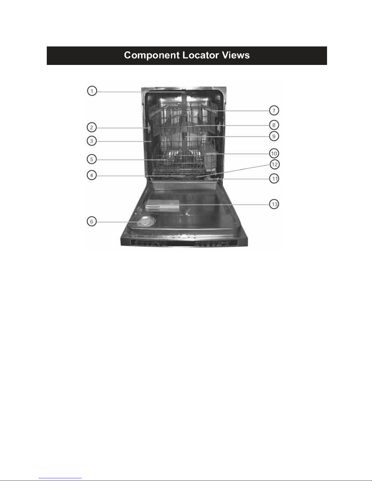
COMPONENTLOCATORVIEWS………………………………………………………………………………………………….…..10
COMPONENTS…………………………………………………………………………………………………………………….….……..13
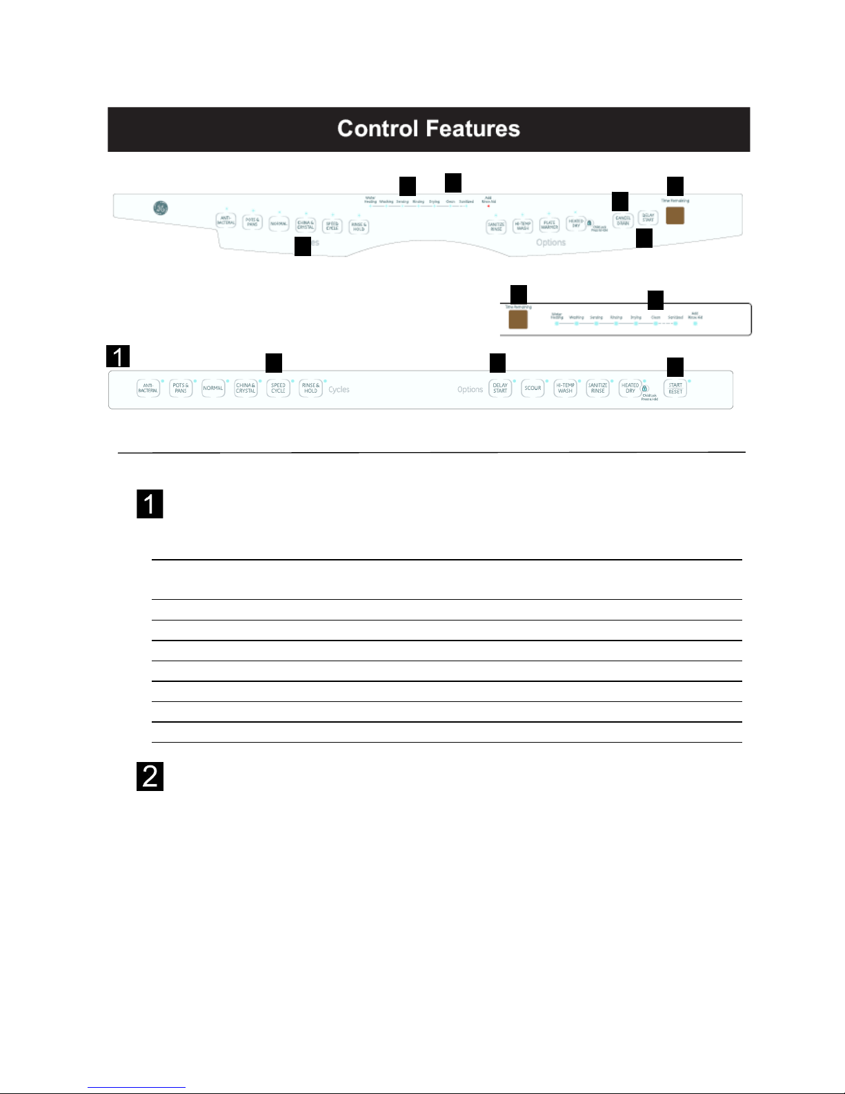
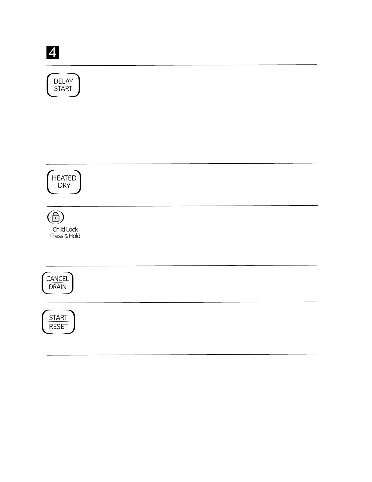
CONTROLFEATURES…………………………………………………………………………………………………..……………………6
CONTROLBOARD……………………………………………………………………………………………………………………..……20
TESTMODE……………………………………………………………………………………………………………………..…………….16
DETERGENT/RINSEMODULE………………………………………………………………………………………………..………..21
DOORINTERLOCKSWITCH………………………………………………………………………………………………..……………21
DOORPANEL………………………………………………………………………………………………..……………..…………………19
DRAINSYSTEM……………………………………………………….………………………………………………………….………….17
FILLFUNNEL……………………………………………………….………………………………………………………….…………..….14
HEATINGELEMENT………………………………………….………………………………………………………………………...….16
LOWERSPRAYWASHARM,FINEFILTER,ANDINLETCOVER…………………………………………………………..14
MAINCONDUIT……………………………………………………….………………………….……………………………………..….14
MEMBRANEKEYPAD………………………………………………………………………………..……………………..….…………19
MIDDLESPRAYARM………………………………………………………………………………..……………………..….………….13
NOMENCLATURE………………………………………………………………………………..……………………..….…………………4
SCHEMATIC………………………………………………….………………………………………….…………………..…….………….25
STRIPCIRCUITS………………………………………………….………………………………………….…………….…..…………….24
THERMISTOR………………………………………………….………………………………………….…………….…..……………….15
TOPSPRAYARM……………………….………………………………………….…………….…………………………...…………….14
TROUBLESHOOTING…………….………………………………………….…………….…………………………...……….….…….22
TURBIDITYSENSOR………………………………………………….………………………………………….…………….….……….17
USINGTHEDISHWASHERWITHTHEUPPERRACKREMOVED…………………………………………………………13
WASHCYCLES…………………………………………………………………………………………………………………………………15
WARRANTY………………………………………………….………………………………………….…………………..…….………….27
WATERVALVEANDFLOODSWITCH…………………………………….……………………………………..…….…………...17
WATERVALVETEST………………………………………….……………………………………………………………..….……….…18

‐4 ‐
Model Number
Serial Number
The model number and serial number are located inside the door jam. The first two characters of the
serial number identify
1 2 3 4 5 6 7 8 9
H
M7 0 0 0 0 1 H
(1) Date Code-Month- (Alpha)
(2) Calendar Year Code (Alpha)
(3) Model Class Code
(4) (5) (6) (7) & (8) Serial Number
(9) Manufacturing Location
Column 1. denotes the fiscal month of manufacture.
Column 2. denotes the fiscal year of manufacture (See Date of Manufacture Code Table
below)
Column 3 denotes the product being produced (regardless of Brand).
Model Class Code for Built-In Dishwasher Products = 7.
G L D 9 3 1 2 P 0 0 W W
Product Type
D=Built-In
Brand
G=GE
Size
L=Long Door
Platform
9 = Fully Integrated
Feather Pack
Exterior Colour
WW=White
BB=Black
SS=Stainless
Enegineering
Model Suffix
Model Year
Designator
Number of
Buttons

‐5 ‐
Columns 4 to 8 denotes the order of manufacture within a given time period. The sequence will
start with 00001 and progress until 99999 is reached or the fiscal month has
changed. The 5 digits need not be reset to the start of the numbering sequence
each month. This is left to the discretion of the factory.
Column 9 A letter, which will designate where the appliance was manufactured
according to the following code: H= Haier.
DATE OF MANUFACTURE CODE TABLE (For column 1 & 2):
Month of Manufacture Year of Manufacture
A – Jan A 2001, 2013
D – Feb D 2002, 2014
F – Mar F 2003, 2015
G – Apr G 2004, …..
H – May H – 1993 2005
L – June L – 1994 2006
M – July M – 1995 2007
R – Aug R – 1996 2008
S – Sept S – 1997 2009
T – Oct T – 1998 2010
V – Nov V – 1999 2011
Z – Dec Z – 2000 2012
Example:
Using the example from the previous page,
HM700001H:
H = May
M = 2007
7 = Built-In Dishwasher
00001 = sequential production number
H = Haier

‐6 ‐
状态指示灯Indicators vary by models)
The Status display tells you what is happening while the dishwasher is in operation and may flash, indicating a
Control Settings
Status Indicator Lights
(Indicators vary by models)
The status dislay tells you what is happening while the dishwasher is in operation and may flash,
indicating a malfunction. The lights will come ON indicating the sequence of the dishwasher operation.
SENSING
Displayed while the turbidity sensor is measuring the amount of soil and temperature of
water. The dishwasher will adjust the selected cycle to achieve optimal performance.
WASHING Displayed during prewash and main wash periods.
RINSING Displayed during rinse periods.
DRYING Displayed during dry periods
.
SANITIZED Displayed when cycle has met sanitization conditions.
CLEAN Displayed when a wash cycle is complete and enhancements are complete.
ADD RINSE AID Displayed when the rinse aid is empty.
WATER HEATING Displayed when the dishwasher heat the water to a setting temperature.
Time Remaining Display
During operation, 2 digital display shows the time remaining until the cycle is complete, if the remaining
time is less than 100 minutes, the display will show the exact minutes remaining, assuming T as the the
remaining time. If 100 minutes <= T < 120 minutes,the display will show 2h, if 120 minutes <= T <
180minutes,the display will show 3h,The rest may be deduced by analogy.
1 2
3 4
2
3 45
6
5
6

‐7 ‐
3Cycles
ANTI-BACTERIA
(on GLD9312 & GLD8312 models)
11.5 gal., 110 min.
This cycle raises the water temperature in the final rinse to sanitize your dishware. The cycle length
will vary depending on the temperature of your inlet water.
NOTE: The Anti-Bacteria cycle is monitored for sanitization requirements. If the cycle is interrupted
during or after the main wash portion or if the incoming water temperature is so low that adequate
water heating cannot be achieved, the sanitizing conditions may not be met. In these cases, the
sanitized light will not illuminate at the end of the cycle.
NOTE:
NSF-certified residential dishwashers are not intended for licensed food establishments.
POTS & PANS
11.5 gal., 96min.
This cycle is meant for heavily soiled dishes or cookware with dried-on or baked-on soils. This
cycle may not remove burned-on foods. Everyday dishes are safe to be used in this cycle.
NORMAL WASH
11.5 gal., 94min.
This cycle is for medium/heavily soiled dishes and glassware.
SPEED CYCLE
3.2gal., 33 min.
This cycle is for everyday dishes and glassware.
CHINA CRYSTAL
4.9 gal., 53 min.
This cycle is specifically designed to reduce the risk of melting plastic items and improve plastic
drying. For removing red tomato-based stains, GE recommends the use of Cascade Plastic.
RINSE & Hold
1.6 gal., 12 min.
For rinsing partial loads that will be washed later. Do not use detergent with this cycle.
NOTE: On the GLD8110 Series models dishwasher have not ANTI-BACTERIA cycle.
NOTE: This dishwasher is equipped with an Sensor; therefore, cycle length and time may vary depending on soil
conditions.
NOTE: Only the Anti-Bacteria, cycle has been designed to meet the requirements of Section 6, NSF 184 for soil
removal and sanitization efficacy.

‐8 ‐
Options
The light above the selected pad will be ON to indicate which option has been selected.
DELAY HOURS
You can delay the start of a wash cycle for up to 12 hours on GLD8110 & GLD8310 Series or 24
hours on GLD9310 Series).
Press the
DELAY START
pad to choose the number of hours you want to delay the start of the cycle;
then press
START/RESET.
GLD8100–GLD8312 Series: The machine will count down and start automatically at the correct time.
GLD9312 Series: After closing the door, the machine will count down and automatically start at the
correct time.
NOTE:
To cancel the DELAY START selection before the cycle begins, press the DELAY START pad until the display is
blank.
HEATED DRY
When selected, the cycle will run longer with heating elements on to improve dry performance.
Shuts off the drying heat option. Dishes will air dry naturally to save energy.
NOTE: Cannot be selected with Rinse & Hold cycle.
CHILD LOCK
You can lock the controls to prevent any selections from being made. Or you can lock the controls
after you have started a cycle.
Children cannot accidentally start dishwasher by touching pads with this option selected.
To unlock the dishwasher controls, press and hold the
HEATED DRY
pad for 3 seconds. To
lock
the
dishwasher, press and hold the
HEATED DRY
pad for 3 seconds.
CANCEL/DRAIN(on GLD8110 & GLD8312 Series)
Touch the CANCEL/DRAIN pad to cancel the cycle. The water is pumped out if need. This takes
approximately 2 minutes.
START/RESET (on GLD9312 Series)
Open the door slowly to prevent splash-out. Touch the START/RESET pad to cancel the cycle. If the
START/RESET Light is on, close the door until the water pumps out(this takes approximately 2
minutes-the display will show 2) and the display is off.
When the display is off, the dishwasher can be reprogrammed and restarted.

‐9 ‐
Start
GLD8110-GLD8312 Series
Close the dishwasher door and selected the cycle and options. Water fill begins immediately and
approximately 90 seconds later the wash action begins.
GLD9312 Series
Open the dishwasher door, After selecting the cycle and options, touch the
START/RESET
pad. Close the door
and then Water fill begin after approximately 10 seconds. Wash action begin approximately 90 seconds later
The dishwasher will always display your last selection and enhancements. If you don’t want to change the
settings, simply touch the
START/RESET
pad to ready the dishwasher and close the door to begin the cycle.
Clean
The
Clean
light is illuminated when the selected cycle and enhancements (not included Speed & Rinse&Hold
Cycle) are complete.

‐10 ‐
Inside cabinet view
1. UpperSpray
2. Top Rack Track
3. Water Inlet Opening (in tub wall)
4. Lower Spray Arm
5. Bottom Rack
6. Vent System
7. Split Folding Utility Shelf (4)
8. Adjustable Top Rack
9. Middle Spray Arm
10. Removable Silverware Basket
11. Overfill Protection Float
12. Heating Element
13. Detergent and Rinse Aid Dispenser

‐11 ‐
Door View (Panel removed)
Left side View

‐12 ‐
Bottom View

‐13 ‐
Using the Dishwasher with the Upper
Rack Removed Middle Spray Arm
1. Unsnap and remove the end cap on each side
of the rails.
2. Pull the rack straight out and off the rails.
3. Replace the end caps.
4. Push the rails all the way back into
the dishwasher.
1. Check holes in spray arm for bits of
china, seeds, and other foreign matter.
2. Check spray arms for rotation.
Removal and Replacement
1. Pull upper rack all the way out.
2. Remove plastic bottom of middle spray
arm. This will allow the middle spray arm
and bearing to be removed.
Note:
Install middle spray arm with spray jets
facing the upper rack. Place bearing between
spray arm screw and bottom of the middle arm.
5. Slide the shower nozzle attachment over
the spout.
6. The dishwasher is now ready for use.
Note: Always use the shower nozzle when the
upper rack is removed. Note: If the upper rack experiences poor cleaning
problems, ensure the middle spray arm is turning
freely. If not, disassemble the middle spray arm and
clean the bearing surface, then reassemble.
Unsa
p

‐14 ‐
Lower Spray Arm, Fine Filter, and Inlet
Cover
Check the holes in spray arm for bits of china,
seeds, and other foreign matter. Also check the
spray wash arms for rotation. If soil is present,
clean fine filter screen.
The lower spray wash arm can be removed by
gently lifting and rotating it counterclockwise.
The nut hub can be removed by rotating it
counterclockwise.
Caution: Use care to avoid breaking the clip on
the hub when removing the main conduit from
hub.
Note:
When installing the fine filter, make sure
the drain port of the filter is engaged with the
drain for the fine filter.
Top Spray Arm
Check the holes in spray wash arm for bits of
china, seeds, and other foreign matter. Also
check the spray wash arms for rotation.
To remove the top spray wash arm, remove the
upper rack (See Middle Spray Arm), then remove
the screw and top spray wash arm.
Main Conduit
The main conduit supplies water to the middle
and upper spray wash arms.
Removal and Replacement
1. Pull upper rack all the way out.
2. Push the tab on the outer slide cap in
and remove the slide cap.
3. Remove the upper rack.
Fine Filter
Drain Port
Drain For
Fine Filter
Lower
Spray Arm
Moutng Scre
w
Main Conduit
Nut Hub
ine Filtr
Assebly
ov Inlet
4. Release the bottom conduit tab.
5. Release 2 center conduit tabs and remove
the main conduit.
Fill Funnel
The top section of the fill funnel separates from
the main body. The fill funnel body is held in place
by a nut (located on the inside of the dishwasher).
Rotate the nut counterclockwise to remove the
main body. There is an O-ring seal between the
fi l l funnel and dishwasher tub. Make certain the
O-ring is fully seated when reinstalling.
Coarse Filter
Float Dome
Hub
Main Conduit
Ta
b
Nut
O‐Ring

‐15 ‐
Wash Cycles
CYCLE
MAX # OF
PRE-WASH
CYCLES
WASH
CYCLE
MAX #
RINSE
CYCLES
WASH
TIME1
WASH
TEMPERATURE
HEATED
DRY
TIME
MIN MAX
Normal
Wash 2 1 4 23 94 1202 1302 10
Speed Wash 0 1 1 33 120 1303 10
China Crystal 1 1 1 53 1303 1353 10
Pots & Pans 2 1 4 38 96 1403 1503 15
Anti-Batirical 2 1 4 42 110 1503 1603 20
Rinse & Hold 0 0 1 12 12 / / /
Time is in minutes
Temperature is in degrees Fahrenheit
1.) Cycle times include water fill and drain
2.) Heater on in main wash and final urinse
Circulation Pump and Motor
The dishwasher must be removed from its
installation to gain access to the circulation pump
and motor. The circulation pump can be activated
using Test Mode.Refer to schematic or strip circuit
for motor resistance value.
Before removing the circulation pump, remove the
water from the sump with a syringe.
It is important to remember the motor does not start
immediately when the dishwasher cycle has
started. If the motor hums, but will not start, make
certain the pump impeller is free from obstruction
and the motor shaft can turn freely.
The terminals on the induction motor are labeled
L1 and N. The motor is thermally protected (internally)
through the L1 side. The wiring connector is blue to
match the wire leading to the motor. It is designed
to fit only one way on the terminals. Make certain
the connector is fully seated when installing.
Circulation Pump and Motor Strip Circuit

‐16 ‐
HeatingElement
The heating element can be activated using TEST
Mode.
The dual-wattage heating element produces 850
watts during wash, to help heat the water, and an
effective wattage due to cycling of 541 watts during
the dry cycle.
Water inlet temperature must be at least 120 °F for
proper drying. Lower water inlet temperature will
prevent proper convection air movement and
increase drying time substantially.
If the problem is that the dishes are not drying
correctly, don’t overlook the rinse agent. A rinse
agent will improve the water sheeting action and
drying performance.
It is normal for the stainless steel tub and inner door
panel to retain water droplets even though the dishes
are dry.
Heating element Strip Circuit
The heating element nuts are located on the
underside of the washer, near the door. Ample force
is required to remove the nuts. Removing the
dishwasher from installation may be required.
TestMode
In standby mode, push HI-TEMP, HEATED-DRY and
HI-TEMP WASH, the machine will enter into the process of
Test Mode. After entering the self inspection mode, all
lights will be ON and the display will show 88, then operate
the unit according to the following order:
zTouch the POTS & PANS the inlet water valve will
work for 90 seconds
zTouch the NORMAL, the wash pump will work for 2
minutes and stop for 1 minutes, then repeat.
zTouch the CHINA pad, the detergent dispenser will
work for 1 minute and stop for 2 minutes, then
repeat.
zTouch the Speed pad, the heating element and wash
pump will work simultaneously for 1 minute and stop
for 1 minute, then repeat.
zTouch the RINSE&HOLD pad, the heating element will
work for 5 minutes and stop for 5 minutes, then
repeat
zTouch the SANITIZE RINSE pad, the drain pump will
work for 2 minutes and stop for 1 minute, then
repeat.
zTouch the HI-TEMP pad, the wax motor will work for
1 minute and stop for 1 minute, then repeat.
TurbiditySensor
The turbidity sensor is located in the front of sump.

‐17 ‐
The turbidity sensor measures the amount of suspended
particles in the wash water in the sump. The control sends
the turbidity sensor a pulse width modulated 5 volt signal
for calibration and usage during operation.
Note: If short circuit or open circuit happens to the sensor,
the dishwasher will operate the shortest cycle time, and
may cause the bad wash performance.
By measing the turbidity level, the control module can
conserve energy on lightly soiled loads by skipping
unnecessary cycles.
Turbidity Sensor Circuit
Thermistor
Thermistor is located on the right down side of the sump.
The turbidity’s resistance has a negative temperature
coefficient. As the temperature increase, the resistane
goes d
The thermistor’s resistance has negative temperature
coefficient. As the temperature increase, the resistance
goes down. At 75℉,the resistance is approximately 11.6k
Ω. At 140℉, the resistance is approximately 2.7kΩ.
DrainSystem
The drain system cosists of the following components:
zAuxiliary drain pump
zsump
zCheck valve(in line with tube)
zDrain house(includes two drain hose, one with
one-way check valve)
The inlet cover prevents large particles from entering the
sump. Water entering the drain pump is not filtered by the
fine filter(plastic) or by the sump filter(metal & plastic).
The drain pump is mounted on the sump and contains a
one way check valve. The drain pump is controlled by the
control board and can be activated using
Testing Mode.
Auxiliary drain pump stip Circuit
The drain pump utilizes a 120V AC motor. The motor
should read approximately 25Ω
Water Valve and Flood Switch
The water valve is a 120 VAC solenoid valve that is
switched on/off by the control board. The flood switch acts
as a safety switch ONLY and does not control normal
operation of the water valve. The flood switch opens the L
side of the water valve circuit.
+5V
1
2
3
Thermistor

‐18 ‐
The switch is normally open. The weight of the flood
switch float holds the switch closed. The flood switch will
not stop the flow of water if the valve sticks open from a
mechanical failure.
The water valve can be replaced with the dishwasher
installed.
WARNING: Disconnect power to dishwasher before
servicing water valve and flood switch.
The valve is secured to the clip by 2 Philips head screw.
Note: To prevent leaks after installation, ensure that hose
to valve connection is good and that clamp is in place.
WaterValveTest
1. Attept to activate water valve using
Test Mode
. Pump
out water as necessary using
Test Mode
. If an
intermittent failure is suspected, activate water valve 5
times using
Test Mode.
Water valve should stay on for
90 to 120 seconds per activation and should not turn
on and off during the 90 to 120 second activation time.
2. If the water valve is not operating properly or water
level is low, check the follow:
zWater valve, flood switch, flood switch float and
stem The flood switch should open when the
water level is approxiaterly 1/4-in. above the
base(bottom) of the float dome.
zResistance through the water valve solenoid coil
-750Ωto 1200Ω.
Water Valve
Flood Switch
Clamp

‐19 ‐
Door Panel
The door panel covers the main control board, detergent cup, vent, wax motor, louver, and door-interlock switch.
The outer door panel is held in place by 14 screws (7 Phillips head screws per side ).
Note: Ribbon cable(s) connect the keypad membrane (2-digit display on some models) to the control board. Due to
the ribbon length, care must be taken when removing the door panel to ensure that the ribbon cable(s) are not
damaged.
Membrane Keypad
The door panel must be removed to access the membrane keypad (see
Door Panel
).
zWhen removing the membrane keypad, peel the keypad from right to left.
zWhen installing, make sure the membrane button areas and lights align with the keypad.
zOn models with an LED display, the display is held in place plastic clip.
Note: When replacing the keypad membrane, always run the
Test mode
calibrate the keypad membrane to the
control board.

‐20 ‐
P2-1 – Rinse Aid Sensor(on some models), P2-2 – Thermostat,P2-3 – Inlet Valve, P2-4 – Dispenser, P2-6 – Door
Interlock Switch(Double Black Wires), P3 – Drain motor, P5&P9 – Washing Motor, P6 – Heater Element, P7 – Door
Interlock Switch(Double White Wires), P8 – Door Interlock Switch(Single Black Wire), P10 Wax Motor connector,
CN1+CN6 – Door Panel
,
CN2 – Dis
p
la
y
Board.
Control Board
The door panel must be removed to access the control board (see
D
oor Panel
). The main control is
considered a “smart” control, capable of learning the water temperature and turbidity characteristics of the home.
It is normal if the cycle times vary over a period of time from the factory default settings due to temperature and water
quality.
The control module is held in place by two screws that secures the module to the right side of the
inner door panel.
Control Board
This manual suits for next models
2
Table of contents
Other GE Dishwasher manuals

GE
GE GLC4000 Series User manual

GE
GE ADW1000 Series User manual

GE
GE EDW4000 Series How to use

GE
GE GSD4900Z How to use

GE
GE GSD1100M User manual

GE
GE GE Profile Triton GPF475 User instructions

GE
GE Profile PDWT502PII Manual

GE
GE GE Profile PDW7700J User manual

GE
GE PDW1800 Series User manual

GE
GE GLDT696DSS Manual