Installation Preparation
ELECTRICAL REQUIREMENTS
Single Speedcook Installation
Product rating is 120/208 or 120/240 volt, 60 Hz,
30 amps. This product must be connected to a supply
circuit of the proper voltage and frequency and
protected by a time delay fuse or circuit breaker.
Power should be supplied from a separate, dedicated
30-ampere branch circuit. Wire size must conform to
the requirements of the National Electrical Code or the
prevailing local code.
Combined Speedcook and Wall Oven Installation
When installed in combination with a GE/Honogram
single wall oven, use separate electrical junction boxes.
Refer to single oven installation instructions for
electrical requirements of that product.
These connections must be made by a qualified
electrician. All electrical connections must meet
National Electrical Code or prevailing local codes.
Combined Speedcook and Warming Drawer
Installation
When installing the Speedcook oven over a GE or
Monogram electric warming drawer, a separate 120V,
60Hz, properly grounded receptacle must be installed.
See instructions packed with the warming drawer.
,&WARNING
• The electrical power to the oven branch circuit
must be shut off while line connections are being
made.
• Use copper wiring only.
• Electrical ground is required on this appliance.
The free end of the green wire (ground wire)
must be connected to a suitable ground.
This wire must remain grounded to the oven.
If cold water pipe is interrupted by plastic,
non-metallic gaskets, union connections or other
insulating materials, DO NOT use for grounding.
• DO NOT ground to a gas pipe.
• DO NOT have a fuse in the NEUTRAL or
GROUNDING circuit. A fuse in the NEUTRAL or
GROUNDING circuit could result in an electrical
shock.
Check with a qualified electrician if you are in
doubt as to whether the appliance is properly
grounded.
Failure to follow these instructions could result in
serious injury or death.
AADVERTENCIA
Elencendido el@ctricoal circuito paralelo deber(i estar
apagado mientras serealizanlasconexionesde Ifnea.
• Useconductores de cobre 0nicamente.
• Esteelectrodom@sticorequiereque serealice una conexi6n
a tierra. Elextremo libredel cableverde (cablea tierra)debe
estar conectado a una conexi6n a tierra adecuada. Este
cable debe permanecer conectado a la conexi6n a tierra del
homo.
• Sila tuberfa de agua frfa presenta interrupciones por
pkisticos,juntas, conexionesde uniones u otros materiales
aislantes,NOusela misma como conexi6n a tierra.
o NOsedebe conectar a tierra en una tuberfa de suministro
de gas.
REQUISITOSELI_CTRICOS(Cant)
NOposeeun fusible en elcircuito neutro o de conexi6n a
tierra. Unfusible en el circuito neutro o de conexi6n a tierra
podrfa ocasionar una descarga el_ctrica.
• Consultea un electricistacalificado o personaldel servicio
sitiene dudas de que el electrodom_stico seencuentre
conectado a tierra apropiadamente.
Si no se siguen estas instrucciones, se podr6n
producir lesiones graves o la muerte.
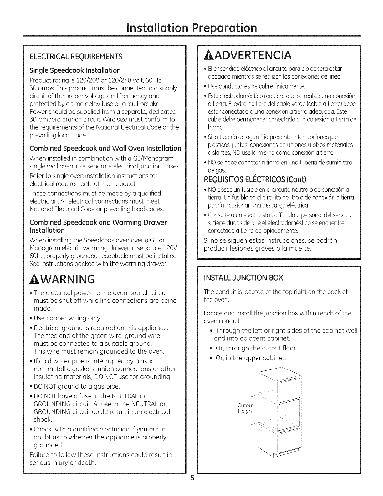
INSTALLJUNCTION BOX
The conduit is located at the top right on the back of
the oven.
Locate and install the junction box within reach of the
oven conduit.
Through the left or right sides of the cabinet wall
and into adjacent cabinet.
Or, through the cutout floor.
Or, in the upper cabinet.
5


M Service manual")