GE AVM4160 User manual

i
Installation
Instructions Over the Range
Microwave Oven
AVM4160,JNM3161,and JVM3160
Questions? Carl 800. GE.CARES (800.432.2737) or Visitour Website at: GEAppliances.com i
BEFOREYOU BEGIN
Read these instructions completely and carefully.
• IMPORTANT- Savethese
instructions for local inspector's use,
• IMPORTANT- Observea,,
governing codes and ordinances,
• Note to Installer -Be sure to leave these
instructions with the consumer,
• Note to Consumer - Keep these instructions
for future reference,
• Skill level - Installation of this appliance requires basic
mechanical and electrical skills,
Proper installation is the responsibility of the installer,
Product failure due to improper installation is not
covered under the warranty,
Throughout this manual, features and appearance may
vary from .your model.
49-40675-1
(06-13 GE)
READ CAREFULLY.
KEEP THESE INSTRUCTIONS.

Installation
CONTENTS
Instructions
[_ Outside Back Exhaust .................................. 20-23
Installation Overview ................................ 20
General information
important Safety instructions ........................................ 3
Electrical Requirements .................................................. 3
Tools You Will Need ......................................................... 4
Hood Exhaust ................................................................. 5,6
Damage - Shipment/Installation .................................. 7
Parts included ................................................................... 7
Preparing Rear Wall for
Outside Back Exhaust ................................ 20
Attach Mounting Plate to Wall .......... 20, 21
Preparation of Top Cabinet ....................... 21
Adapting Blower for Outside
Back Exhaust .......................................... 21, 22
Mount the Microwave Oven .............. 22, 23
Mounting Space ................................................................ 8
Step-by-step installation guide
Placement of Mounting Plate ................................... 9-11
Removing the Mounting Plate ............................. 9
Finding the Wall Studs .......................................... 9
Determining Mounting Plate Location .............. 10
Aligning the Mounting Plate .............................. 11
installation Types ..................................................... 12-23
_ Recirculating .................................................. 13-15
Attach Mounting Plate to Wall ................ 13
Preparation of Top Cabinet ...................... 13
Installing the Charcoal Filter .................... 14
Mount the Microwave Oven .............. 14, 15
Installing the Charcoal Filter
without Top Access ............................ 15
[_ Outside Top .....................................
Exhaust 16-19
Attach Mounting Plate to Wall ................. 16
Preparation of Top Cabinet ....................... 17
Adjust Blower Motor .................................. 17
Assemble and Install Adaptor .................. 18
Mount the Microwave Oven ..................... 18
Adjust the Exhaust Adaptor ...................... 19
Connecting Ductwork ................................ 19
Before You Use Your Microwave Oven ..................... 24
2

Installation Instructions
IMPORTANT SAFETYINSTRUCTIONS
A qualified electrician must perform a ground continuity
check on the wall receptacle before beginning the
installation to ensure that the outlet box is properly
grounded, If not properly grounded, or if the wall
receptacle does not meet electrical requirements noted
(under ELECTRICAL REQUIREMENTS), a qualified electrician
should be employed to correct any deficiencies.
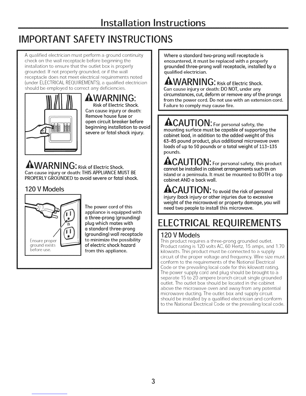
AWARNING:
Risk of Electric Shock.
Can cause injury or death:
Remove house fuse or
open circuit breaker before
beginning installation to avoid
severe or fatal shock injury.
_VV/_K|_I| |_1_: Risk of Electric Shock.
Can cause injury or death: THIS APPLIANCE MUST BE
PROPERLY GROUNDED to avoid severe or fatal shock.
120 V Models
before use,
The power cord of this
appliance isequipped with
a three-prong (grounding}
plug which mates with
a standard three-prong
(grounding} wall receptacle
to minimize the possibility
of electric shock hazard
from this appliance.
Where a standard two-prong wall receptacle is
encountered, it must be replaced with a properly
grounded three-prong wall receptacle, installed by a
qualified electrician.
AWARN ING:RiskofElectricShock.
Can cause injury or death: DO NOT, under any
circumstances, cut, deform or remove any of the prongs
from the power cord, Do not use with an extension cord,
Failure to comply may cause fire,
Ar, Ai iTir i
_U||U|_: For personal safety, the
mounting surface must be capable of supporting the
cabinet load, in addition to the added weight of this
63-85 pound product, plus additional microwave oven
loads of up to 50 pounds or a total weight of 113-135
pounds.
ACAUTION: For personal safety, this product
cannot be installed in cabinet arrangements such as an
island or a peninsula. It must be mounted to BOTH a top
cabinet AND a back wall.
|_i'_U||U|\l: To avoid the risk of personal
injury (back injury or other injuries due to excessive
weight of the microwave) or property damage, you will
need two people to install this microwave.
ELECTRICAL REQUIREMENTS
120 V Models
This product requires a three-prong grounded outlet.
Product rating is 120 volts AC, 60 Hertz, 15 amps, and 1.70
kilowatts. This product must be connected to a supply
circuit of the proper voltage and frequency. Wire size must
conform to the requirements of the National Electrical
Code or the prevailing local code for this kilowatt rating.
The power supply cord and plug should be brought to a
separate 15 to 20 ampere branch circuit single grounded
outlet. The outlet box should be located in the cabinet
above the microwave oven and away from any potential
microwave ducting. The outlet box and supply circuit
should be installed by a qualified electrician and conform
to the National Electrical Code or the prevailing local code.
3

Installation Instructions
TOOLS YOU WILL NEED
#1 and #2 Phillips Pencil
screwdriver
Tin snips (for cutting
damper, if required)
Scissors (to cut
template, if necessary)
Gloves
Safety goggles
@:==_
Saw (saber, hole or keyhole)
Level
Lhh,,l.,.JJ._._l,d.J,.L.bJ,,._.,,_.h.l,._.,.L.hL,,J.,.]
Ruler or tape measure and
straight edge
Electric drill with %6", 7A6",
_" and %" drill bits
Carpenter square
(optional)
Filler blocks or scrap
wood pieces, if needed
for top cabinet spacing
(used on recessed bottom
cabinet installations only)
Stud finder Hammer (optional) Duct and masking
tape
4

Installation Instructions
HOOD EXHAUST
NOTE: Read these next two pages only if you plan to vent your exhaust to the outside. If you plan to recirculate the air
beck into the room, proceed to page 6. Below ore examples of Outside Top Exhaust end Outside Beck Exhaust duct system
layouts. Note the position of the microwave oven relative to the duct system.
OUTSIDE TOP EXHAUST {EXAMPLE ONLY}
The following chart describes an example of one possible
ductwork installation,
m
L_]
DUCT PIECES
II
[]
Roof Cap
12 Ft,Straight Duct
(6" Round)
Rectangular-to-Round
Transition Adaptor*
EQUIVALENT NUMBER EQUIVALENT
LENGTH x USED = LENGTH
24 Ft, x (1)
12 Ft, x (1)
5 Ft, x (1)
Equivalent lengths of duct pieces are based on actual tests and
reflect requirements for good venting performance with any vent hood,
Total Length =
24 Ft,
12 Ft,
5 Ft,
41 Ft.
*IMPORTANT: If a rectangular-to-round transition adaptor is used, the bottom corners of the damper will
have to be cut to fit, using the tin snips, in order to allow free movement of the damper,
OUTSIDE BACK EXHAUST {EXAMPLE ONLY}
The following chart describes an example of one possible
ductwork installation,
DUCT PIECES
Wall Cap
3 Ft, Straight Duct
3}4" x 10" Rectangular)
90 ° Elbow
EQUIVALENT NUMBER EQUIVALENT
LENGTH* x USED = LENGTH
40 Ft, x (1) =
S Ft, x (1) =
10 Ft, x (2) =
Equivalent lengths of duct pieces are based on actual tests and
reflect requirements for good venting performance with any vent hood,
Total Length =
40 Ft,
3 Ft,
20 Ft,
63 Ft.
NOTE: For back exhaust, care should be taken to align exhaust with space between studs, or wall should be prepared
at the time it is constructed by leaving enough space between the wall studs to accommodate exhaust,
5

Installation Instructions
NOTE: If you need to install ducts, note that the total duct
length of 3_¼'' x 10" rectangular or 6" diameter round duct
should not exceed 140 equivalent feet.
Outside ventilation requires a HOOD EXHAUST DUCT,
Read the following carefully:
NOTE: It is important that venting be installed using
the most direct route and with as few elbows as possible,
This ensures clear venting of exhaust and helps prevent
blockages, Also, make sure dampers swing freely and
nothing is blocking the ducts.
Exhaust connection:
The hood exhaust has been designed to mate with
a standard 3X" x 10" rectangular duct,
If a round duct is required, a rectangular-to-round
transition adaptor must be used, Do not use less than
a 6" diameter duct.
Maximum duct length:
For satisfactory air movement, the total duct length of
3X'x 10" rectangular or 6" diameter round duct should
not exceed 140 equivalent feet.
Elbows, transitions, wall and roof caps, etc.,
present additional resistance to airflow and are equivalent
to a section of straight duct which is longer than their actual
physical size, When calculating the total duct length, add the
equivalent lengths of all transitions and adaptors plus the
length of all straight duct sections, The chart below shows
you how to calculate total equivalent ductwork length using
the approximate feet of equivalent length of some typical
duct pieces,
DUCT PIECES
Rectangular-to-Round
Transition Adaptor*
Wall Cap
90 ° Elbow
EQUIVALENT
LENGTH
5 Ft,
40 Ft,
10 Ft,
NUMBER
USED
()
()
( )
EQUIVALENT
LENGTH
Ft,
Ft,
Ft,
(_ 45 ° Elbow 5 Ft, x ( ) : Ft,
90 ° Elbow 25 Ft, x ( ) = Ft,
_ 45 °Elbow 5Ft, x ( ) = Ft,
Roof Cap 24 Ft, x ( ) = Ft,
Straight Duct 6" Round or 1 Ft, x ( ) = Ft,
3X" x 10" Rectangular
Total Ductwork = Ft.
* IMPORTANT: If a rectangular-to-round transition
adaptor is used, the bottom corners of the damper
will have to be cut to fit, using the tin snips, in order
to allow free movement of the damper.
Equivalent lengths of duct pieces are based on actual tests and
reflect requirements for good venting performance with any vent
hood.
6

Installation Instructions
DAMAGE- SHIPMENT/
INSTALLATION
• If the unit is damaged in shipment, return
the unit to the store in which it was bought for
repair or replacement,
• If the unit is damaged by the customer, repair or
replacement is the responsibility of the customer,
If the unit is damaged by the installer (if other than
the customer), repair or replacement must
be made by arrangement between customer
and installer,
PARTSINCLUDED
HARDWARE PACKET
PART QUANTITY
Wood Screws
(3/16"x 2") 2
Toggle Bolts (and
wing nuts)(1/4" x 3") 4
Self-aligning Machine
Screw (1/4"-28 x 3
3-1/4")
j Nylon Grommet (for
metal cabinets) 2
Power Cord Strap
(plastic) 1
You will find the installation hardware contained
in a packet with the unit, Check to make sure you
have all these parts,
NOTE: Some extra parts are included,
PARTS INCLUDED
ADDITIONAL PARTS
I
PART QUANTITY
TOPCABINETTEMPLATE
REA__LL_E_pLA_EO
Top Cabinet
Template
Rear Wall
®Template
Installation
Instructions
and
Owners
Manual
Grease
Filters
Exhaust
Adaptor
Tray
Turntable
Ring
1
1
7

Installation Instructions
MOUNTING SPACE
66" or
more from
the floor
to the
top of the
microwave
oven
........ Bottom edge of
cabinet needs to
be 30" or more
from the cooking
surface
Backsplash
NOTES:
• The space between the cabinets must be 30" wide
and free of obstructions,
• If the space between the cabinets is greater than
30", a Filler Panel Kit may be used to fill in the gap
between the microwave oven and the cabinets,
Your Owner's Manual contains the kit number for
your model,
This microwave oven is for installation over ranges
up to 36" wide,
If you are going to vent your microwave oven to the
outside, see Hood Exhaust Section for exhaust duct
preparation,
When installing the microwave oven beneath
smooth, flat cabinets, be careful to follow the
instructions on the top cabinet template for power
cord clearance,
• Maximum cabinet depth above and beside the unit
is 123A".
. For models setup in Recirc Exhaust: Do not allow
cabinetry or other objects to block the airflow of the
vent,
. The product should not be installed over any cooktop
or range with a combined BTU greater than 60,000
BTU,
8

Installation Instructions
--]PLACEMENT OFTHE MOUNTING PLATE
%REMOVING THE MICROWAVE
OVEN FROM THE CARTON/
REMOVING THE MOUNTING PLATE
%Open the box and fold back all four carton flaps fully
against the carton sides, Remove the following items
from the protective foam; installation instructions,
filters, exhaust adaptor, damper, and the small
hardware bag, Do not remove the foam protecting
the front of the microwave oven,
Then carefully roll the microwave oven and carton
_] over onto the top side, The microwave oven should
be resting in the foam,
arton
Foam
%
%
%
%
Pull the carton up and off the microwave oven,
The mounting plate is attached to the back of the
microwave oven. Remove the two screws holding it
to the microwave oven. The plate will be used as the
rear wall template and for mounting the microwave
oven to the wall.
Set the microwave oven upright, Remove and
properly discard plastic bags and foam,
Open the microwave oven door and remove the
plastic sheet and tape from inside the microwave
oven door, Remove the tape covering the turntable
hub,
FINDING THE WALL STUDS
t Wall
I_ Find the studs, using one of the following methods:
A. Stud finder.
OR
B. Use a hammer to tap lightly across the mounting
surface to find a solid sound. This will indicate
a stud location.
I_ After locating the stud(s), find the center by probing
the wall with a small nail to find the edges of the stud.
Then place a mark halfway between the edges.
The center of any adjacent studs should be 16" or 24"
from this mark.
I_Draw line down the of the studs.
acenter
IMPORTANT: The microwave must be connected to at
least one wall stud.
9

Installation Instructions
DETERMINING MOUNTING PLATE LOCATION UNDER YOUR CABINET
Plate Position - flat bottom cabinet Plate Position - recessed cabinet bottom
Mounting Plate Tabs
_Touching the Cabinet
'.Bottom
Mounting Plate
Tabs Touching the
Back Frame of the
Cabinet
At least 30", up to 36"
30" to Cooktop
I
Plate Position - cabinet with front overhang
o
Mounting Plate
with Tabs Below
Cabinet Bottom
the Same Distance
Front
Overhang Depth
30" to Cooktop
I
Your cabinets may have decorative trim that interferes
with the microwave oven installation. You may need to
remove the decorative trim to install the microwave oven
properly and to make it level.
THE MICROWAVEOVENMUST BELEVEL.
Use a level to make sure the cabinet bottom is level,
If the cabinets have a front overhang, install the
mounting plate down the same distance as the front
overhang depth. This will keep the microwave oven level.
_i_ Measure the inside depth of the front overhang.
[_ Draw a horizontal line on the back wall an equal
distance below the cabinet bottom as the inside depth
of the front overhang.
[_ For this type of installation with front overhang,
align the mounting tabs with this horizontal line, not
touching the cabinet bottom as described in Step D.
10

Installation Instructions
ALIGNING THE MOUNTING PLATE
Hole C
CAUTION:
Wear gloves to avoid cutting
fingers on sharp edges.
I I
I I
I I
Draw a
Vertical Line
-- on Wall from
Center of Top
Cabinet
I I
I I
f
Area E I
I
I
I I
I I
I
Notch
I I
Hole B
Hole D
_i_ Draw a vertical line on the wall at the center of the 30"
wide space,
[]Use the mounting plate as the template for the rear wall,
Place the mounting plate on the wall, making sure that
the tabs are touching the bottom of the cabinet or
the level line drawn in Step C for cabinets with front
overhang. Line up the notch and center line on
the mounting plate to the center line on the wall.
[] While holding the mounting plate with one hand, draw
circles on the wall at holes A, B, C, and D (see illustration
above/actual plate marked with arrows), Four holes
must be used for mounting.
NOTE: Holes C and D are inside area E,If neither C nor D
is in a stud, find a stud somewhere in area E and draw a
fifth circle to line up with the stud, It is important to use
at least one wood screw mounted firmly in a stud
to support the weight of the microwave oven,
Set the mounting plate aside,
AWARN ING: iskofelectricshock.Cancause
injury or death. Take care to not drill into electrical wiring
inside walls or cabinets.
_!_ Drill holes on the circles, If there is a stud, drill a _U' hole
for wood screws, For holes that don't line up with a stud,
drill a 5A"hole for toggle bolts,
NOTE: DO NOT MOUNT THE PLATE AT THIS TIME.
11

Installation Instructions
-2-IINSTALLATIONTYPES {ChooseA,B or C}
This microwave oven is designed for adaptation to the
following 3 types of ventilation:
A. Recirculating (Non-Vented Ductless}
B. Outside Top Exhaust (Vertical Duct}
C. Outside Back Exhaust IHorizontal Duct}
NOTE: This microwave oven is shipped assembled for
Recirculating. Select the type of ventilation required for
your installation and proceed to that section.
-_ RECIRCULATING
{NON-VENTED DUCTLESS) OUTSIDE TOP EXHAUST
{VERTICAL DUCT)
Adaptor in Place For
Outside Top Exhaust
A Charcoal Filter Accessory Kit is required for the non-vented
exhaust, (See your Owner's Manual for the kit number,)
OUTSIDE BACK EXHAUST
{HORIZONTAL DUCT)
12

Installation Instructions
RECIRCULATING (Non-Vented Ductless)
INSTALLATION OVERVIEW
A1. Attach Mounting Plate to Wall
A2. Prepare Top Cabinet
A3. Install Charcoal Filter (Supplied with AVM4160 and
JVM3160 models)
A4. Mount the microwave oven
A5. Installing/Replacing the Charcoal Filter Without
Access to Top Screws and the Unit Has Already
Been Mounted,
f
ATTACH THE MOUNTING PLATE
TO THE WALL
Attach the plate to the wall using toggle bolts, At least
one wood screw must be used to attach the plate to
a wall stud,
_!_ Remove the toggle wings from the bolts,
[_ Insert the bolts into the mounting plate through
the holes designated to go into drywall and reattach
the toggle wings to ¾" onto each bolt,
To use toggle bolts:
Spacing for Toggles More
-_-,--_i-"--=- Than Wall Thickness
i Toggle Wings
Bolt End
[_ Place the mounting plate against the wall and insert
the toggle wings into the holes in the wall to mount
the plate,
NOTE: Before tightening toggle bolts and wood screw,
make sure the tabs on the mounting plate touch the
bottom of the cabinet or the horizontal level line when
pushed flush against the wall and that the plate is
properly centered under the cabinet,
Ar, al i-r,r_R,
Bl_.w_'_U||g|_: Be careful to avoid pinching
fingers between the back of the mounting plate and
the wall.
[] Tighten all bolts, Pull the plate away from the wall
to help tighten the bolts,
13
r_ USETOPCABINETTEMPLATE
FORPREPARATIONOFTOPCABINET
You need to drill holes for the top support screws and
a hole large enough for the power cord to fit through,
• Read the instructions on the TOP CABINET
TEMPLATE,
• Tape it underneath the top cabinet,
• Drill the holes, following the instructions on the TOP
CABINET TEMPLATE,
_L_'lU||g|_ : Wear safety goggles when
drilling holes in the cabinet bottom.

Installation Instructions
INSTALLING THE CHARCOAL FILTER
_!] Remove 2 screws on top of microwave oven,just
above the grille panel, using a Phillips screwdriver,
If two screws are not accessible, see section A6,
_] Open the door,
_] Remove the grille,! |
[_ Insert the top of the filter up and into the grooves on
both sides of the inside of the top opening, Once you
have cleared the bottom tab, push the bottom of the
filter in until it rests in place behind the tab,
Grooves in Filter (dashed to show
Microwave for
[] Replace the grille
by inserting the top
grill flange into the
slots in the case as
shown, _",,
_] Replace the 2 top screws,
[_ Close the door,
| MOUNT THE MICROWAVE OVEN
_.t.ul,u,_: Toavoidther_skofpersonal
injury (back injury or other injuries due to excessive
weight of the microwave} or property damage, you
will need two people to install this microwave.
IMPORTANT: Do not grip or use handle during
installation,
WARNING:RiskofElectricShock.Can
cause injury or death: If installing unit with metal
countertops, cover the edge of the power supply
cord hole with the power supply cord bushing.
IMPORTANT: If filler blocks are not used, case damage
may occur from overtightening screws,
NOTE: When mounting the microwave, thread power
cord through hole in bottom of top cabinet, Keep it
tight throughout Steps 1-3, Do not pinch cord or lift
microwave oven by pulling cord,
_i] Lift microwave, tilt it forward, and hook slots at
back bottom edge onto four lower tabs of mounting
plate,
Power Cord
[]Rotate front of microwave oven up against cabinet
bottom,
14

Installation Instructions
| MOUNT THE MICROWAVE OVEN
(cont.}
[] Insert 3 self-aligning screws (1A"-28 x 21A")through
outer top cabinet holes, Turn two full turns on each
screw,
Cabinet Front
Cabinet Bottom Shelf
Filler Block
This distance
--_quivalent | can NOT
I to Depth | exceed 2"
of Cabinet | to ensure
Recess _[ proper
_' installation
gning Screw
Microwave Oven Top
Self-Aligning Screws
[]Tighten the three screws to the top of the
microwave oven, (While tightening screws, hold
the microwave oven in place against the wall and
the top cabinet,)
[_ Install grease filters, See the Owner's Manual
packed with the microwave oven,
INSTALLING/REPLACING THE
CHARCOAL FILTER WITHOUT
ACCESSTO TOPSCREWSAND THE
UNIT HASALREADYBEENMOUNTED
DISMOUNT THE MICROWAVE OVEN
I CAUTION: Toovoid the risk of personal
injury (back injury or other injuries due to excessive
weight of the microwave} or property damage, you will
need two people to uninstall this microwave.
IMPORTANT: Do not grip or use handle during removal,
WARNI NG:RiskofElectricShock.Can
cause injury or death: If removing unit with metal
countertops, cover the edge of the power supply cord
hole with the power supply cord (nylon grommet).
IMPORTANT: If filler blocks are not used, case damage
may occur from overtightening screws,
_i] Loosen the 3 screws on the top of the microwave
oven (inside the cabinet),
J
I_ Lift microwave, tilt it forward and unhook slots at
back bottom edge from the four lower tabs of the
mounting plate,
15
[] Replace the filter using instructions from section A3,
[_ Reinstall unit following instructions from A4,

Installation Instructions
I-B-IOUTSIDE TOP EXHAUST{Vertical Duct)
INSTALLATION OVERVIEW
B1. Attach Mounting Plate to Wall
B2. Prepare Top Cabinet
B3. Adjust Blower Motor
B4. Install Exhaust Adaptor
BS. Mount Microwave Oven
B6. Adjust Exhaust Adaptor
B7. Connect Ductwork
I
i
I I
I I
| ATTACH THE MOUNTING PLATE
TO THE WALL
A
\
C" D
Attach the plate to the wall using toggle bolts, At least
one wood screw must be used to attach the plate to
a wall stud, Recommended locations on the mounting
plate are indicated by A, B,C and D,
_!_ Remove the toggle wings from the bolts,
[]Insert the bolts into the mounting plate through
the holes designated to go into drywall and reattach
the toggle wings to ¾" onto each bolt,
16
To use toggle bolts:
Spacing for Toggles More
÷l_"-_i_---Than Wall Thickness
I
Mounting ]Toggle Wings
Plate.
Mounting Plate Bolt End
[] Insert the toggle wings into the holes in the wall and
place the mounting plate against the wall,
NOTE: Before tightening toggle bolts and wood screw,
make sure the tabs on the mounting plate touch the
bottom of the cabinet when pushed flush against the
wall and that the plate is properly centered under the
cabinet,
JIIk_I-_U/IUI_: Be careful to avoid pinching
fingers between the back of the mounting plate and
the wall.
[_ Tighten all bolts, Pull the plate away from the wall
to help tighten the bolts,

Installation Instructions
USETOP CABINET TEMPLATE FOR
PREPARATION OF TOP CABINET
You need to drill holes for the top support screws,
a hole large enough for the power cord to fit through,
and a cutout large enough for the exhaust adaptor.
• Read the instructions on the TOP CABINET TEMPLATE.
•Tape it underneath the top cabinet.
•Drill the holes, following the instructions on the TOP
CABINET TEMPLATE.
Ar, AI ITl_l
Jl_P_U|I U|_I: Wear safety goggles when
drilling holes in the cabinet bottom.
| ADJUST BLOWER MOTOR
[] Remove the screws holding the blower unit and
the screws securing the blower plate. Remove
the blower plate from the outer case by sliding it
toward the back of the microwave and pulling up.
Blower Motor Screws
IBlower Plate
Blower
"_"- Motor
Screw
I_] Carefully pull out the blower unit. The wires will
extend far enough to allow you to adjust the
blower unit.
r_ ADJUST BLOWER MOTOR (cont.)
O: ...s _-" Back of
._ i f.%_-z
--.-_._s_" Mlrcrowave
13] Roll the blower so that fan blade openings are
facing the top of the oven. Place the blower back
into the opening.
Fan Blades
Wire<_ 7 _I
Note: Make sure the wires remain routed through the
openings in the motor frame. To avoid damage to
the fan motor wiring, insert motor carefully such that
the fan motor wiring does not contact the microwave
power cord bracket.
WARNING:.iskofElectricShock.
Can cause injury or death. Do not pull or stretch the
blower unit wiring. Hake sure the wires are not
pinched.
[_]Slide the blower plate back onto the microwave
by placing the side tabs into the slots and pushing
gently until the back tab is seated into the rear slot.
Replace 3 screws.
I
Tab
Side Slot Rear Slot
17

Installation Instructions
ASSEMBLEAND INSTALL ADAPTOR
Dampe_
Blower
Plate
_l_ Place the microwave oven in its upright position, with
the top of the unit facing up and the front of the unit
facing toward you,
Remove the screw on the back side of the blower
plate and raise the blower plate off of the microwave,
[]Slide the damper from left to right into the tabs on the
blower plate, The yellow tape on the damper should
be facing away from you,
[_ Remove the yellow tape from the damper, Make sure
that the damper pivots easily before mounting
microwave oven.
You will need to make adjustments to assure proper
alignment with your house exhaust duct after the
microwave oven is installed,
[] Position the blower plate with damper back on the
microwave and secure it with the screws that were
removed,
MOUNT THE MICROWAVE OVEN
, CAUTION: To avoid the risk of personal
injury (back injury or other injuries due to excessive
weight of the microwave) or property damage, you
will need two people to install this microwave.
IMPORTANT: Do not grip or use handle during
installation,
AWARNING: RiskofElectricShock.Can
cause injury or death: If installing unit with metal
countertops, cover the edge of the power supply
cord hole with the power supply cord bushing.
IMPORTANT: If filler blocks are not used, case damage
may occur from overtightening screws,
NOTE: When mounting the microwave, thread power
cord through hole in bottom of top cabinet, Keep it
tight throughout Steps 1-3, Do not pinch cord or lift
microwave oven by pulling cord,
_l_ Lift microwave, tilt it forward, and hook slots at
back bottom edge onto four lower tabs of mounting
plate, Power Cord
[]Rotate front of microwave oven up against cabinet
bottom,
18

Installation Instructions
| MOUNT THE MICROWAVE OVEN
{cont.)
[] Insert a self-aligning screw through top-center
cabinet hole, Temporarily secure the microwave
oven by turning the screw at least two full
turns after the threads have engaged, (It will be
completely tightened later,) Insert 2 self-aligning
screws (W'-28 x 21¼,,)through outer top cabinet
holes, Turn two full turns on each screw,
J
J
Cabinet Front
Cabinet Bottom Shelf
Filler Block
_. This distance
--_quivalent |can NOT
I to Depth |exceed 2"
to ensure
I of Cabinet | proper
!_' Recess _ installation
-- Self-Aligning Screw
Microwave Oven Top
[] Tighten the three screws to the top of the microwave
oven, (While tightening screws, hold the microwave
oven in place against the wall and the top cabinet,)
_3 Install grease filters, See the Owner's Manual packed
with the microwave oven,
ADJUST THE EXHAUST ADAPTOR
Open the top cabinet and adjust the exhaust adaptor
to connect to the house duct,
Damper Back of
Microwave
Oven
| CONNECTING DUCTWORK
House Duct
[]Extend the house duct down to connect to
the exhaust adaptor,
_] Seal exhaust duct joints using duct tape,
19

Installation Instructions
- OUTSIDE BACK EXHAUST{Horizontal Duct)
INSTALLATION OVERVIEW
Cl. Prepare Rear Wall
02. Attach Mounting Plate to Wall
03. Prepare Top Cabinet
C4. Adjust Blower
05. Mount the Microwave Oven
PREPARING THE REAR WALL
FOR OUTSIDE BACK EXHAUST
You need to cut an openinginthe rear wallforoutside
exhaust,
• Read the instructions on the REAR WALL TEMPLATE,
• Tape it to the rear wall, lining up with the holes
previously drilled for holes A and B in the mounting
plate,
• Cut the opening, following the instructions of the
REARWALL TEMPLATE,
[_ ATTACH THE MOUNTING PLATE
TO THE WALL
! __ii_i_ii
: i ...........-_ iii/i i
Attach the plate to the wall using toggle bolts, At least
one wood screw must be used to attach the plate to
a wall stud,
_!] Remove the toggle wings from the bolts,
[]Insert the bolts into the mounting plate through
the holes designated to go into drywall and reattach
the toggle wings to ¾" onto each bolt,
2O
Other manuals for AVM4160
3
This manual suits for next models
3
Table of contents
Languages:
Other GE Microwave Oven manuals

GE
GE JES942 User manual

GE
GE PEB7227 User manual

GE
GE Spacemaker II JEM824G User manual

GE
GE JE1530 Use and care manual

GE
GE JET322G Installation instructions

GE
GE JHP60G Installation instructions

GE
GE JEB1860DM User manual

GE
GE JX1527CSH User manual

GE
GE JES740D User manual

GE
GE Advantium SCA2001 User manual