31-7000092 Rev. 2 9
Installation Instructions
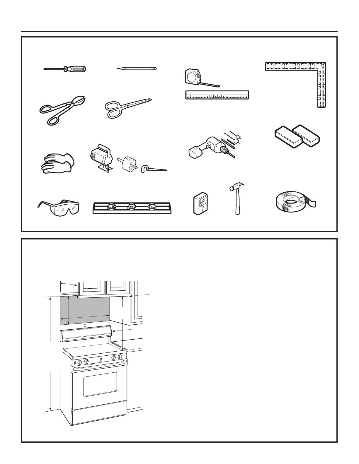
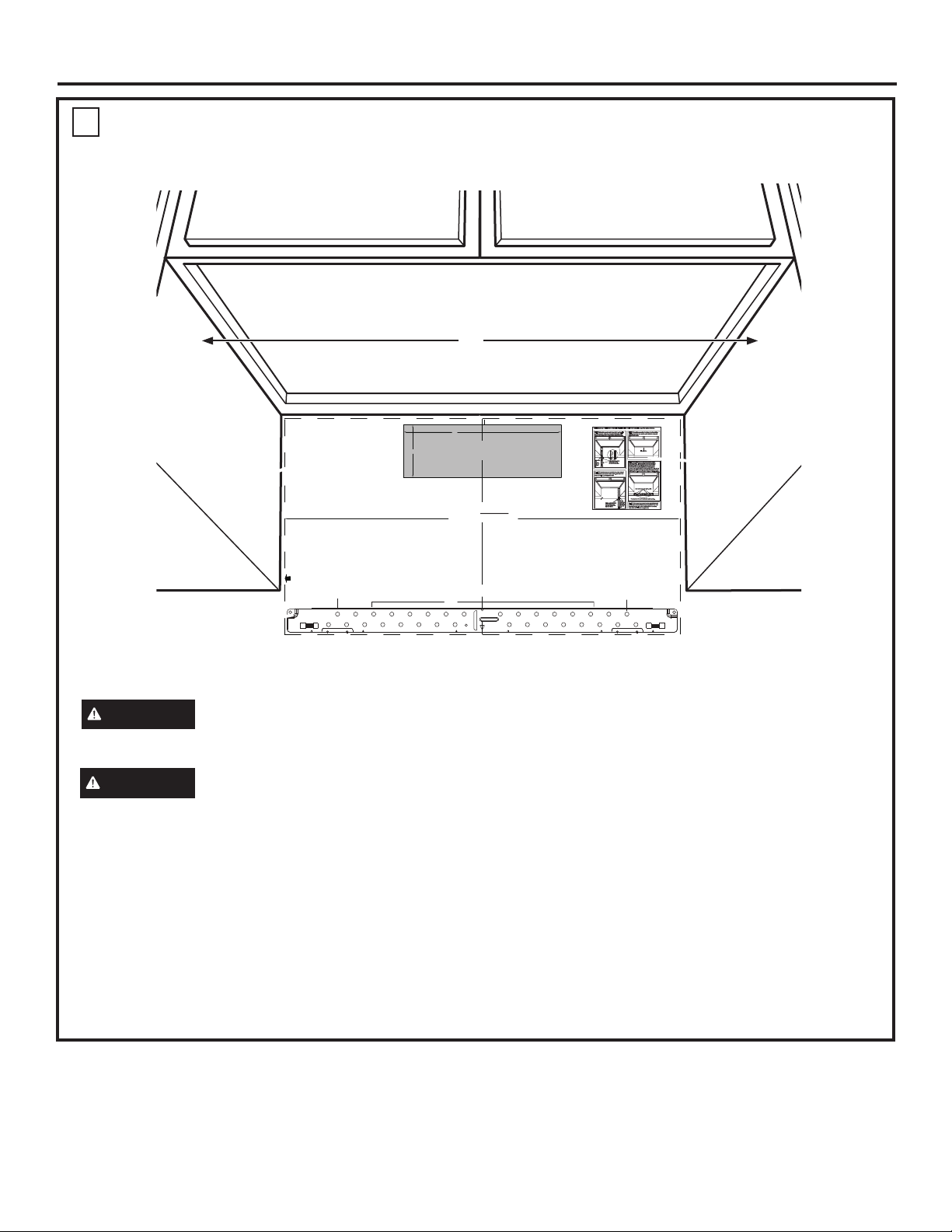
CUT HOLE THROUGH REAR WALL FOR EXHAUST ADAPTOR
12"
4"
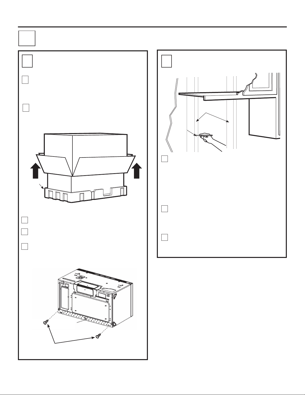
NOTE: IT IS VERY IMPORTANT TO
READ AND FOLLOW THE DIRECTIONS
IN THE INSTALLATION INSTRUCTIONS
BEFORE PROCEEDING WITH THIS
REAR WALL TEMPLATE.
This Rear Wall Template serves to position the bottom
mounting plate and to locate the horizontal exhaust
outlet.
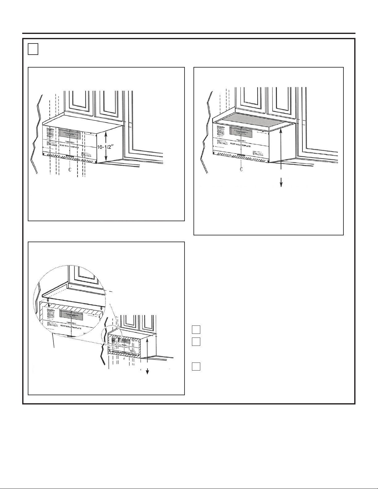
1. Use a level to check that the template is positioned
accurately.
2. Locate and mark at least one stud on the left or
right side of the centerline.
NOTE:It is important to use at least one wood
screw mounted firmly in a stud to support the weight
of the microwave. Mark two additional, evenly spaced
locations for the supplied toggle bolts.
3. Drill holes in the marked locations. Where there is
a stud, drill a 3/16" hole for wood screws. For holes
that do not line up with a stud, drill 5/8" holes for
toggle bolts.
NOTE::DO NOT INSTALL THE MOUNTING PLATE
AT THIS TIME.
4. Remove the template from the rear wall.
5. Review the Installation Instruction book for your
installation situation.
Darle vuelta a la hoja para consultar la
versión en Español.
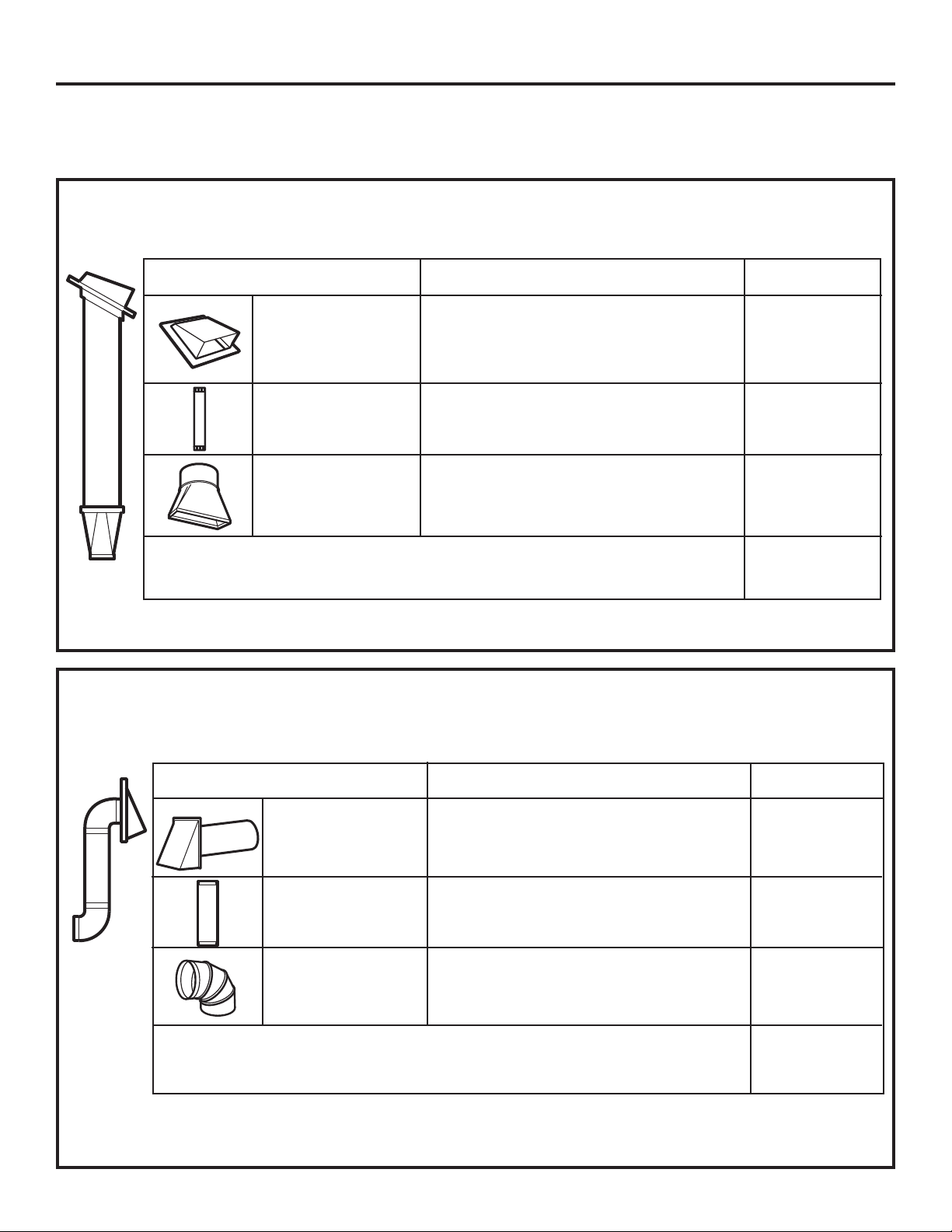
CAUTION - IF EXHAUST ADAPTOR IS POSITIONED OUTSIDE
RECOMMENDED DIMENSION, GREASE-LADEN AIR WILL
DISCHARGE INTO HOUSE STRUCTURE
30” MINIMUM WIDTH REQUIRED
REAR WALL TEMPLATE
F. CUT OUT FOR HORIZONTAL
OUTSIDE EXHAUST
Locate and mark holes to align with holes in the
mounting plate.
IMPORTANT:
LOCATE AT LEAST ONE STUD ON EITHER SIDE OF
THE CENTERLINE.
MARK THE LOCATION FOR 2 ADDITIONAL, EVENLY
SPACED TOGGLE BOLTS IN THE MOUNTING PLATE
AREA.
Locate and mark holes to align with holes in the
mounting plate.
IMPORTANT:
LOCATE AT LEAST ONE STUD ON EITHER SIDE OF
THE CENTERLINE.
MARK THE LOCATION FOR 2 ADDITIONAL, EVENLY
SPACED TOGGLE BOLTS IN THE MOUNTING PLATE
AREA.
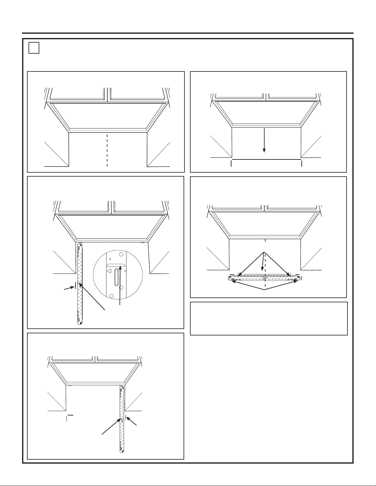
Trim the rear wall template along the dotted line.
3/8" TO EDGE
C
NOTES:
- 13” Max Cabinet Depth
- 15” deep cabinets require additional steps using
an additional installation kit: JX15BUMP
OPTION 1 OPTION 2
STEP1: Installer uses bracket tomake 2 marks. First
markis made by using the stampled slot in bracket.
Secondmark is made on the ouside edge of bracket.
STEP3: Installer uses a level todraw a horizontal line
thatconnects the two marks made with the stamped
slotin the bracket.
STEP2: Installer moves bracket tothe other side of
thecabinets and makes 2 moremarks. Marks are the
sameas STEP 1, just opposite side.
STEP4: Installer uses marks to install bracketin
correctposition. The bracketis to be installed per
standardrequirements(at least one wood screw
mountedin a stud, two additional evenlyspaced
locationsfor toggle bolts). Mark hole location A,B,C and
Dby placing the mounting bracketon the wall as shown
inthe picture. Hole C and or D must be in a WALLSTUD.
STEP5: Set mounting bracket aside and drill holes at
allmarked locations.If there is a stud, drill a 3/16” hole
forwood screws.For holes that do not line up with a
stud,drill a 5/8” hole for a toggle bolt.
Makeamark here, along
insidebottomof the
stampedslotprovided.
Makeamark
here,
evenwith
bottomof
stamped
slot
Makeamark here, along
insidebottomof the
stampedslotprovided
(sameasStep 1).
Makea
markhere,
evenwith
bottomof
stamped
slot
Horizontalline
A
C
D
B
Placebracketwithin the lines created in previoussteps.
Markholelocations for A, B, C, and D.
NOTE:Refer to step C “DETERMINING MOUNTING PLATE LOCATION UNDER YOUR CABINET on page 10 for aligning instructions.
C
AB
MARKING THE MOUNTING HOLES
OPTION 1: USE PAPER REAR WALL TEMPLATE
WARNING Risk of electric shock. Can cause
injury or death. Take care to not drill into electrical
wiring inside walls or cabinets.
This Rear Wall Template serves to locate the mounting
holes for the bottom mounting plate and to locate the
horizontal exhaust outlet.
1. Use a level to check that the template is positioned
accurately.
2. Locate and mark at least one stud on the left or right
side of the centerline.
NOTE: It is important to use at least one wood screw
mounted firmly in a stud to support the weight of the
microwave.
3. Mark the hole location on the wall using the template
at holes A and B. Mark at least one hole location
in area C that lines up with the location of a stud. A
minimum of three holes must be used for mounting.
4. Drill holes in the marked locations. Where there is a
stud, drill a 3/16” hole for wood screws. For holes that
do not line up with a stud, drill 5/8” holes for toggle
bolts.
NOTE: DO NOT INSTALL THE MOUNTING PLATE AT
THIS TIME
5. Remove the template from the rear wall.
D
CAUTION Wear gloves to avoid cutting fingers
on sharp edges.
30”


M Service manual")