manuals.online logo
Brands
  1. Home
  2. •
  3. Brands
  4. •
  5. GE
  6. •
  7. Range
  8. •
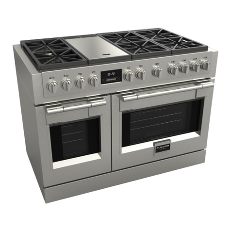
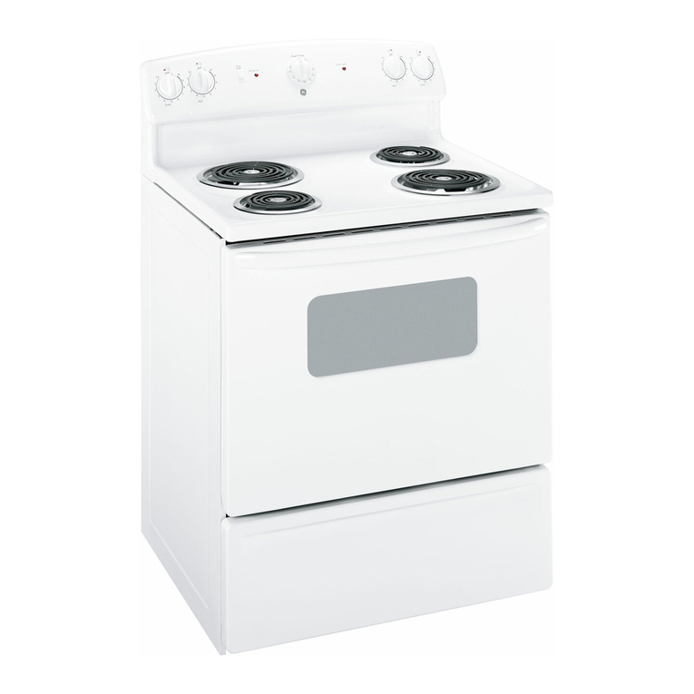
  9. GE Monogram ZDP48N4G User manual

GE Monogram ZDP48N4G User manual

Other manuals for Monogram ZDP48N4G

6

This manual suits for next models

13

Other GE Range manuals

GE 49-80651 User manual

GE

GE 49-80651 User manual

GE CR411 Operating instructions

GE

GE CR411 Operating instructions

GE PHS925ST1SS User manual

GE

GE PHS925ST1SS User manual

GE Profile JGSP48WHWW Manual

GE

GE Profile JGSP48WHWW Manual

GE JMP28 User manual

GE

GE JMP28 User manual

GE P2B935YPFS User manual

GE

GE P2B935YPFS User manual

GE J2B915 Original instructions

GE

GE J2B915 Original instructions

GE JCBP65 Operating instructions

GE

GE JCBP65 Operating instructions

GE JGBP35 Original instructions

GE

GE JGBP35 Original instructions

GE 164D3333P033 User manual

GE

GE 164D3333P033 User manual

GE JBP22 User manual

GE

GE JBP22 User manual

GE JGBP25SENSS Manual

GE

GE JGBP25SENSS Manual

GE JSP46DP Manual

GE

GE JSP46DP Manual

GE JGBS18DEN Manual

GE

GE JGBS18DEN Manual

GE ZGP484NG User manual

GE

GE ZGP484NG User manual

GE JB645STSS Manual

GE

GE JB645STSS Manual

GE JGBP28EELBB User manual

GE

GE JGBP28EELBB User manual

GE Profile PB970SMSS Manual

GE

GE Profile PB970SMSS Manual

GE PGB930 User manual

GE

GE PGB930 User manual

GE 183D5580P236 Original instructions

GE

GE 183D5580P236 Original instructions

GE RAS240 User manual

GE

GE RAS240 User manual

GE PGS930 User manual

GE

GE PGS930 User manual

GE RGBS330 User manual

GE

GE RGBS330 User manual

GE RGB790DETBB User manual

GE

GE RGB790DETBB User manual

Popular Range manuals by other brands

Maytag MGR5875QDW - 30 Inch Gas Range Use and care guide

Maytag

Maytag MGR5875QDW - 30 Inch Gas Range Use and care guide

Frigidaire FFGF3024SS use & care

Frigidaire

Frigidaire FFGF3024SS use & care

Capital Precision Series GCR484W Specifications

Capital

Capital Precision Series GCR484W Specifications

Officine Gullo GGS8P Installation and use instruction

Officine Gullo

Officine Gullo GGS8P Installation and use instruction

LG LSD4913 Series owner's manual

LG

LG LSD4913 Series owner's manual

Kenmore 4101 - Elite 30 in. Slide-In Electric Range installation instructions

Kenmore

Kenmore 4101 - Elite 30 in. Slide-In Electric Range installation instructions

Moffat Blue Seal Evolution G576 Technical data sheet

Moffat

Moffat Blue Seal Evolution G576 Technical data sheet

CornuFé C1NF user guide

CornuFé

CornuFé C1NF user guide

LG LDG3015ST Manual De Propietario

LG

LG LDG3015ST Manual De Propietario

Whirlpool RF350PXP Use and care guide

Whirlpool

Whirlpool RF350PXP Use and care guide

Samsung FCQ321HTUW Service manual

Samsung

Samsung FCQ321HTUW Service manual

Kenmore 790.45712 Use & care guide

Kenmore

Kenmore 790.45712 Use & care guide

Wolf CHR CHSSR owner's manual

Wolf

Wolf CHR CHSSR owner's manual

Smeg Built-in Microwave Oven Instructions for the user

Smeg

Smeg Built-in Microwave Oven Instructions for the user

Zanussi ZCG054G user manual

Zanussi

Zanussi ZCG054G user manual

Samsung NX58M9960P series installation manual

Samsung

Samsung NX58M9960P series installation manual

Hotpoint RB524R Use and care & installation instructions

Hotpoint

Hotpoint RB524R Use and care & installation instructions

Frigidaire FEF367CGSA Factory parts catalog

Frigidaire

Frigidaire FEF367CGSA Factory parts catalog

manuals.online logo
manuals.online logoBrands
  • About & Mission
  • Contact us
  • Privacy Policy
  • Terms and Conditions

Copyright 2025 Manuals.Online. All Rights Reserved.

GE Monogram ®
Installation
Instructions
Professional
Ranges
48" Natural Gas Models
ZDP48N4G
ZDP48N6R
ZDP48N6D
48" LP Gas Models
ZDP48L4G
ZDP48L6R
ZDP48L6D
36" Natural Gas Models
ZDP36N6
ZDP36N4R
ZDP36N4D
36" LP Gas Models
ZDP36L6
ZDP36L4R
ZDP36L4D
30" Natural Gas Modal
ZDP3ON4
30" LP Gas Modal
ZDP30L4
Before you begin--Read these instructions completely and carefully.
IMPORTANT: Save these instructions for local inspector's use.
IMPORTANT: OBSERVE ALL GOVERNING CODES AND ORDINANCES.
NOTE TO INSTALLER: Be sure to leave these instructions with the Consumer.
NOTE TO CONSUMER: Keep these instructions with your Owner's Manual for future
reference.
F!l,,,t:s,,u_,:_l This appliance must be properly grounded. See "Electric Supply", page 7.
For Monogram local service in your area,
1-800-444-1845.
For Monogram Service in Canada,
Call 1-888-880-3030.
For Monogram Parts and Accessories, call
1-800-626-2002.
If you received a damaged range, you should
contact your dealer:
Installation of this range requires basic
electrical, carpentry and mechanical skills.
Proper installation is the responsibility of the
installer. Product failure due to improper
installation is not covered under the GE
Appliance Warranty. See the Owner's Manual
for details.
CAUTION:
THESE RANGES SHOULD BE INSTALLED
IN CONJUNCTION WITH A SUITABLE
OVERHEAD VENT HOOD. Due to the high
heat capacity of this unit, particular attention
should be paid to the hood and duct work
installation to assure it meets local building
codes.
Standard countertop and island installations:
A 1200 CFM hood is recommended for 48"
ranges.
A 600 CFM hood is recommended for 30" and
36" Ranges.
Hoods should be 24" min. deep and the same
width as the cooktop.
grounding must comply with applicable codes.
In the absence of local codes, the gas range
should be installed in accordance with the
National Fuel Gas Code ANSI 223.1, latest
edition and National Electrical Code ANSI/
NFPA 70, latest edition.
CAUTION:
These ranges weigh up to 600 pounds. Some
disassembly will reduce the weight consider-
ably. Due to the weight and size of the range
and to reduce the risk of personal itl,jury or
damage to the product, TWO PEOPLE ARE
REQUIRED FOR PROPER INSTALLATION.
Check local building codes tor the proper
method of gas range installation. Local codes
vary. Installation, electrical connections and
Contents" Design Information
Models Available .................................................................................................................................. 3
Accessory Requirements ..................................................................................................................... 3
Models Dimensions and Clearances ............................................................................................... 4,5
Advance Planning ............................................................................................................................... 6
Tools & Materials Required ................................................................................................................ 6
Installation Preparation
Power Supply Locations ...................................................................................................................... 7
Installation
Step 1: Remove Packaging .................................................................................................................. 8
Step 2: Level the Range ...................................................................................................................... 9
Step 3: Install _mti-Tip Device ............................................................................................................ 9
Step 4: Connect Range to Gas .......................................................................................................... 11
Step 5: Install the Range Backguard ................................................................................................ 11
Step 6: Connect Electrical ................................................................................................................ 12
Step 7: Slide Range Into Position .................................................................................................... 12
Step 8: Replace Oven Doors ............................................................................................................. 12
Step 9: _ssemble & Adjust Burners ................................................................................................. 13
Step 10: Adjustable Low Burner Settings ........................................................................................ 13
Finalize Installation ........................................................................................................................... 13
2
Design Information
Pr@ssional Ranges
Models"
Available
These ranges are factory set fbr either natural
gas or liquid propane gas. Order the model
for your installation situation.
48" Natural Gas Models:
ZDP48N4G
4 gas burners, grill and griddle
ZDP48N6R
6gas burners and grill
ZDP48N6D
6gas burners and griddle
48" Liquid Propane Gas Models:
ZDP48L4G
4 gas burners, grill and griddle
ZDP48L6R
6gas burners and grill
ZDP48L6D
6gas burners and griddle
36" Natural Gas Models:
ZDP36N6
6 gas burners
ZDP36N4R
4 gas burners and grill
ZDP36N4D
4 gas burners and griddle
36" Liquid Propane Gas Models:
ZDP36L6
6 gas burners
ZDP36L4R
4 gas burners and grill
ZDP36L4D
4 gas burners and griddle
30" Natural Gas Model:
ZDP30N4
30" Liquid Propane Gas Model:
ZDP30L4
A ccesso,7
Requirements
All models require the installation of a back-
guard. Abackguard should be ordered at the
same time as the range. Both must be on site
at the time of installation.
Order one backguard for 48" Models:
ZXIB48
1-1/2" high backguard (required for island
installations or installations where back wall is
non-combustible such as brick, ceramic tile,
marble, etc.)
ZX12B48
12" high backguard
ZX22B48
22" high backguard with warming shelf
(2 piece)
Order one backguard for 36" Models:
ZXIB36
1-1/2" high backguard (required for island
installations or installations where back wall is
non-combustible such as brick, ceramic tile,
marble, etc.)
Order one backguard for 30" Models:
ZX1B30
1-1/2" high backguard (required for island
installations or installations where back wall is
non-combustible such as brick, ceramic tile,
marble, etc.)
ZX12B30
9" high backguard
ZX22B30
22" high backguard with warming shelf
2 hgB;':gf00rdW'th
ZX12B36
12" high backguard
ZX22B36
22" high backguard with warming shelf
(2 piece)

Installation Note:
For approved installations to non-combustible back wall materials, consult
material representative to ensure that the material has appropriate resistance
to staining and/or discoloration.
12"High13ackguard
(9" Highfor30"Models)
_rd for
IslandInstallatioasonly
Design Information
Pr@ssional Ranges
Product
Dimensions
& Clearances
1/4"
ii Optionalt
35-1/4"-30-3/4"
48"Wide Range Models 36"Wide RangeModels
_29-1/16"
3-1/4" q_i 12"_
_ High
21-1/4" Shelf
LowBack
-- 0" Clearance
26"
28-1/4'm
31-1/2'm
45-518"
30"Min.
to Combustibles
12"Min to Combustibles
Without BackguardorO"
to Non-CombustibleWall
with 1-1/2"Backguard 36"Min
to
Combustibles
All Models
48"and 36"Range Models
Design Information
Pro/essional Ranges
Product
Dimensions
& Clearances"
35-I/4"-36-8/4"
26-8/4"
, _ \ 9-7/B"
_27-3/8"
-_ _High
21-1/4" Shelf
LowBack
-- o" Clearance
r_q r_q
--26-3/4'm
--29-1/4"
43-7/8"
36"Min.
to Combustibles
i
i
30"Wide Range Models
Note: Refer to Vent
Hoed Installation
Instructions for
hood height above
the range.
18"Min.
I 30"WideRangeHood
Or
36"WideRangeHood
48"WideRangeHood
30"/36"Wide Models4'_
48"Wide Models8"
i
,' 30"/36"Wide Models12"
48"WideModels16"
i
•I i i i _ i
30/36 WldeModels4 ,i,12% _
48 Wide Models8 , ,
i i i
i i
i i
i i
o
8-1/2"
GasSupply
/
, \
\\
0
12"Min.to
t Matedal
i EachSide
o
ElectricalSupply
36"Min. to
Combustible
MaterialFrom
CookingSurface
\"_ 35-3/8"Max.for CounterLevel
36-3/4"Max.with RangeLevelingLegsFullyExtended
Design Information
Pr@ssional Ranges
Advance
Planning
Refer to "Dimensions and Clearances" for
appropriate placement and necessary clear-
ances when planning the installation.
• Cabinetry can not be installed directly above
the range.
• We recommend the installation of a vent
hood above the surface.
-The vent hood must be at least 24" deep.
-The vent hood must be the same width as
the range.
-For 48" models, we recommend the vent
hood blower be 1200 CFM.
-For 30" and 36" models, we recommend the
vent hood blower be 600 CFM.
• Working areas adjacent to the range should
have 18" minimum clearance between
countertop and cabinet bottom.
• Clearance between range and side wall or
combustible material must be at least 12" on
each side.
• Allow 36" min. above the cooking surface to
combustible materials.
• For 48" models, we recommend the vent
hood blower be 1200 CFM.
• For 30" and 36" models, we recommend the
vent hood be 600 CFM.
• Installation must conform with local codes.
In the absence of local codes, the range
must comply with the National Fuel Gas
Code, ANSI Z223.1, latest edition.
A.G.A. approved.
If the range is installed in an island:
•Allow 12" min. clearance at the back to
combustible materials.
7bols &
Materials
.%qui, d:
• Saw
• Measuring tape
• Carpenter's square
• Pipe and fittings as required.
• Manual gas line shut-off valve.
• Gas pressure regulator (supplied)
• Large flat-blade screwdriver
• Pipe wrench
• Drill and appropriate bits
• Safety glasses
• Gas-resistant pipe joint sealant
• 5 foot, 5/8" AGA-certified flexible metal gas
supply line.
-If required by local codes, use solid pipe
fittings.
Note: Purchase new flexible line. DO NOT
USE OLD, PREVIOUSLY USED FLEXIBLE
LINE.
Installation Preparation
Pro/essional Ranges
Pozogr
Supply
Locations
Gas Supply:
•The natural gas models are designed to
operate at 6" to 14" water column pressure.
• The liquid propane models are designed to
operate at 11 to 14" water column pressure.
A regulator is required at the L.R source to
provide a maximum of 14" water pressure to
the range regulator.
• These gas ranges are supplied with 1/2"
NPT female gas connection located at the
left rear cornet:
• A minimum 5/8" dia. metal flexible line is
required.
• For flexible connection, locate pipe stub on
the back wall as illustrated.
-- Use 54hot, 5/8" long flexible gas supply
line.
• For rigid connection, locate the pipe stub as
illustrated.
• Install a manual shut-off valve in the gas
line, in an easily accessible location.
Electric Supply:
These ranges must be supplied with 208/240
volt, 60 Hz., and connected to an individual,
properly grounded branch circuit protected
by a circuit breaker or time delay fuse (50
amp for 48" ranges, 30 amp for 36" ranges
and 25 amps fbr 30" ranges). The receptacle
must be a NEMA 14-50R devise to accept the
4-prong plug supplied with the range.
4" For30"/36"Models
8"Models
12_Flex Line
Supply ///t0 Range
__i" ? 12"For30'736"Models
16"For48"Models
Electrical_
2" Maximum
ProtrusionFrom
Wall ForGas
Supply ""-. 3-1/4"
NEMA14-50R"'-.
Receptacle _
"_._.1/2"
If the electrical service provided does not
meet the above specifications, it is recom-
mended that a licensed electrician install an
approved outlet.
• Locate the electric supply as illustrated.
The range is equipped fbr use with an
electrical supply which uses a separate
grounding conductor (4 wire system).
If this range must be connected to an
electrical system which utilizes a single
conductor for ground and neutral (3 wire
system), the grounding jumper at the
terminal block must be connected. The
grounding jumper is located behind the
fi-ont kick panel.
_Greea
_Red
/
Connec/t
TerminalBlock
/White ,Black
To connect grounding jumper:
• Disconnect restraining clip holding jumper.
• Connect green jumper to open terminal on
neutral (white) portion of the terminal
block.
7
Installation
Pro/essional Ranges
Before moving the range indoors:
• Remove outer carton and packing material
from the shipping base.
DoorHingeRoller
(Closed}
_/ KickPanel
• Remove the kick panel by removing 2 screws
at the top and pulling forward.
Remove oven doors:
• Open the door fully and hold down.
• Close the brass hinge latches to locked
position on each side.
• Carefully, lift and pull the door away from the
range and out of" the frame.
left RearShipping
Screws
RangeMust
beUniformly
Supported
onBraces
The range is secured m the skid with 2 bolts in
the front and 2 "L" brackets on the bottom
flange of the range back. Remove bolts and
"L" brackets.
Due to the weight of these ranges, use a dolly
with soft wheels to move this range.
• Lift the range onto the dolly and move
indoors.
To simplify handling and to reduce the weight
of the range:
• Remove the grates and drawers below the
knobs.
• Remove grill and griddle covers. DO NOT
ATTEMPT TO REMOVE A GRILL OR
GRIDDLE ASSEMBLY
• Remove the broiler pans/literature package
from inside oven (s).
8
Installation
Pr@ssional Ranges
Pu¢_ilove
Packaging
(continued)
36" and 48" Wide Models:
• Remove the panel from the rear of the
shipping pack. Lay the panel on the floor
directly in front of the installation location.
The range should be placed on this panel to
prevent damage to the floor.
All Models:
• Remove the two strips fi'om the oven
interior: Place the strips on the floor at the
lef} and right sides of the installation
location. These strips provide a surface for
sliding the range into the final position and
will prevent damage to the floor. The
leveling legs must rest permanently on these
runner strips.
Level the
Range
Note: Rear range leveling legs are not acces-
sible af}er installation.
• Check to be sure the aclioining cabinets/
countertops are level, fi'ont to back and lef}
to right across the opening of the range.
• Measure the distance fi'om the floor to the
top of the countertop in the left and right
real- corners.
•Acliust the height of the range to countertop
height or higher:
IMPORTANT: The range should always be
installed at countertop height or highetz DO
NOT INSTALL THE RANGE LOWER THAN
ADJACENT COUNTERTOP HEIGHT.
Install
Anti-Tip
Device
• All RangesCanTip
•InjuryCouldResult
•InstallAnti-Tip
BracketProvided
•See Instructions
All Ranges must have an anti-tip device
correctly installed according to these
instructions.
• If the range is pulled out fi'om the wall for
any reason, make sure that the device is
properly engaged when pushed back against
the wall or installation position.
• If the anti-tip device is not engaged, there is
a possible risk that the range can tip over
and cause injury if you or a child stand, sit or
lean on an open door:
[41#10x 2" wood screws
The anti-tip bracket is designed to be installed
on top of the slide (runners) provided with
the range. Any other type of construction may
require special installation techniques to
insure adequate fastening of the anti-tip
bracket to the floor or wall.
• The bracket must be properly installed to
prevent tipping of the range.
• Read the AItAM Anti-Tip Safizty brochure
packed with the product.
Anti-Tip £racket
AHAMAnti-Tip
SafetyBrocMre
Installation
Pro/essional Ranges
Install
Anti-Tip
Device
(continued)
SmallHolesForWood
installations(2Total)\
Wood J
Slide__
Strip
SmallHoleForWood (2}WoodScrewsinto
Installations(2Total) BackWall
(All Installations)
(2)LargeHolesFor \
ConcreteInstallations
Sack
Wall
\Dimension A
Dimension A
A=dels[V'o 112" 5/8" 1/4"
ZDP48 ZDP36 ZDP30
Wood Construction:
• Place the bracket against the back wall, into the
right rear corner of the installation location.
• See Dimension A, position the bracket the
correct distance from the right side. Mark the 2
small screw holes for fastening the bracket to
the floor and remove the bracket.
• Drill two, 1/8" diameter pilot holes.
• Fasten the bracket securely to the floor and wall
using all 4 screws provided.
Concrete or Cement Construction:
Hardware Required (not supplied):
[2] sleeve anchors, lag bolts and washers.
•Place the bracket against the back wall, into the
right rear corner of the installation location.
• See Dimension A, position the bracket the
correct distance from the right side. Mark the 2
large holes for fastening the bracket to the floor
and remove the bracket.
• Drill recommended size holes for the hardware.
• Install the sleeve anchors into the holes and then
install the lag bolts through the bracket. The
bolts must be properly tightened as recom-
mended for the hardware.
• Fasten the bracket securely to the floor.
• Drive wood screws into the back wall.
10