GE ZGP366N User manual

Installation
Instructions
30", 36" and 48"
All Gas Professional Ranges
Pour toutes les cuisini_res
professionnelles au gaz
de 30" (76 cm), 36" (91 cm)
et de 48" (121 cm)
Instructions d'installation
La section fran9aise commence 6 la page 27
Estufas profesionales
completamente a gas
de 30", 36"y 48"
Instrucciones de instalaci6n
La secci6n en espafiol empieza en la p6gina 51
[31-i0755-i]
ii-i0GE

Installation Instructions
BEFORE YOU BEGIN
Read these instructions completely and carefully.
•IMPORTANT Save theseinstructionsfor
localinspector'suse
•IMPORTANT Observeallgoverningcodes
and ordinances
• Note to Installer - Be sure to leave these
instructions with the Consumer.
• Note to Consumer - Keep these instructions
with your Owner's Manual for future reference.
• Completion Time - i to 3 hours.
• Proper installation is the responsibility of the installer.
Product failure due to improper installation is not
covered under the warranty. See Owner's Manual for
warranty information.
-4,WARNING:
This appliance must be properly grounded. Follow
directions in "Electric Supply" of this manual. Failure to
do so may result in electric shock.
For Monogram local service in your area,
1.800.444.1845.
For Monogram Service in Canada,call 1.800.561.3344.
For Monogram Parts and Accessories, call
1.800.626.2002.
If you received a damaged range, you should contact
your dealer.
In the Commonwealth of Massachusetts:
• This product must be installed by a licensed plumber
or gas fitter.
• When using ball type gas shut off valves, they shall be
T-handle type.
• A flexible gas connector, when used, must not exceed
3 feet.
-4,WARNING:
All ranges con tip. Injury could result. Install the
supplied Anti-Tip Bracket provided. See instructions
in this manual or with the bracket.
If sold outside the U.S.and Canada:
_4,WARNING: ifyouwish to use this product
with Liquefied Petroleum (LP}gas containing greater
than 10% butane, you must purchase the butane
conversion kit #WB28K10589. To order, please call
1.888.664.8403 or 1.787.276.4051. Failure to do so
may result in carbon monoxide or fire hazard.
Vent hood Combinations:
A suitable overhead vent hood is required for models
with a grill and is recommended for all other models.
• Install a hood with at least 1200 CFM above o 48"
wide range.
• Install a hood with at least 600 CFM above o 30" or
36" range.
Due to the high heat capacity of this unit, particular
attention should be paid to the hood and ductwork
installation to assure it meets local building codes.
-4,WARNING:
Clearances to horizontal surfaces above the range,
measured to the cooking surface are below. Failure to
comply may result in fire hazard.
• Installations without a hood require 48" minimum to
combustibles.
• A custom hood installation with exposedhorizontol
combustibles surfaces must have an Auto-On
feature.
• For other installations with a hood, refer to hood
installation instructions for specific hood clearances.
,CAUTION:
These ranges weigh up to 700 pounds. Some
disassembly will reduce the weight considerably. Due
to the weight and size of the range and to reduce the
risk of personal injury or damage to the product:
TWO PEOPLEAREREQUIREDFORPROPER
INSTALLATIONOF 36" AND 30" RANGES.
THREEPEOPLEAREREQUIREDFORPROPER
INSTALLATIONOF 48" RANGES.
Leak testing of the appliance shall be conducted
according to the manufacturer's instructions.
Installation must conform with local codes. In the
absence of local codes, the range must comply
with the National Fuel Gas Code, ANSIZ22.K1/NFPA
5/4,latest edition and National Electrical Code ANSI/
NFPA 70 latest addition. In Canada, installation must
conform with the current Natural Gas Installation Code,
CAN/CGA-B1/49.1 or the current Propane Installation
Code, CAN/CGA-B1/49.2,and with local codes where
applicable. This range has been design-certified by CSA
International according to ANSI Z21.1, latest edition
and Canadian Gas Association according to CAN/CGA-
1.1 latest edition.

Design Information
CONTENTS
Design Information
Models Available ......................................................................3
Backsplash Accessories .......................................................3
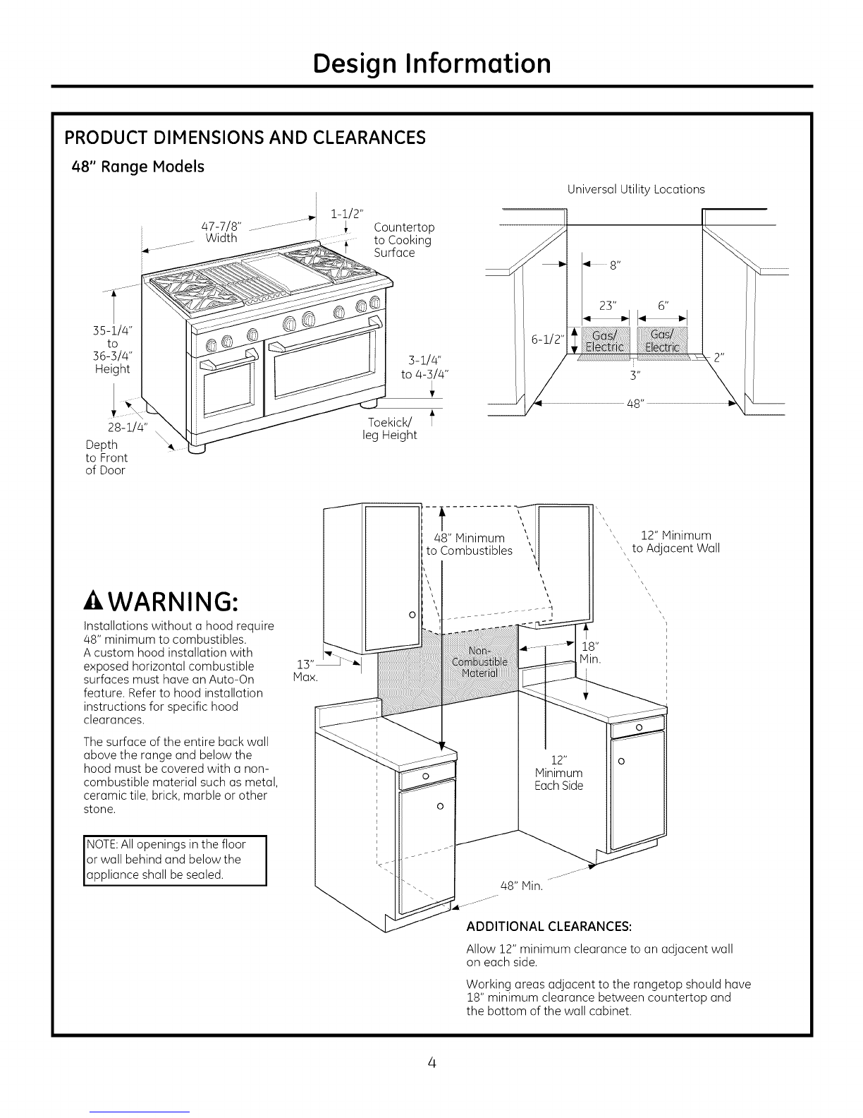
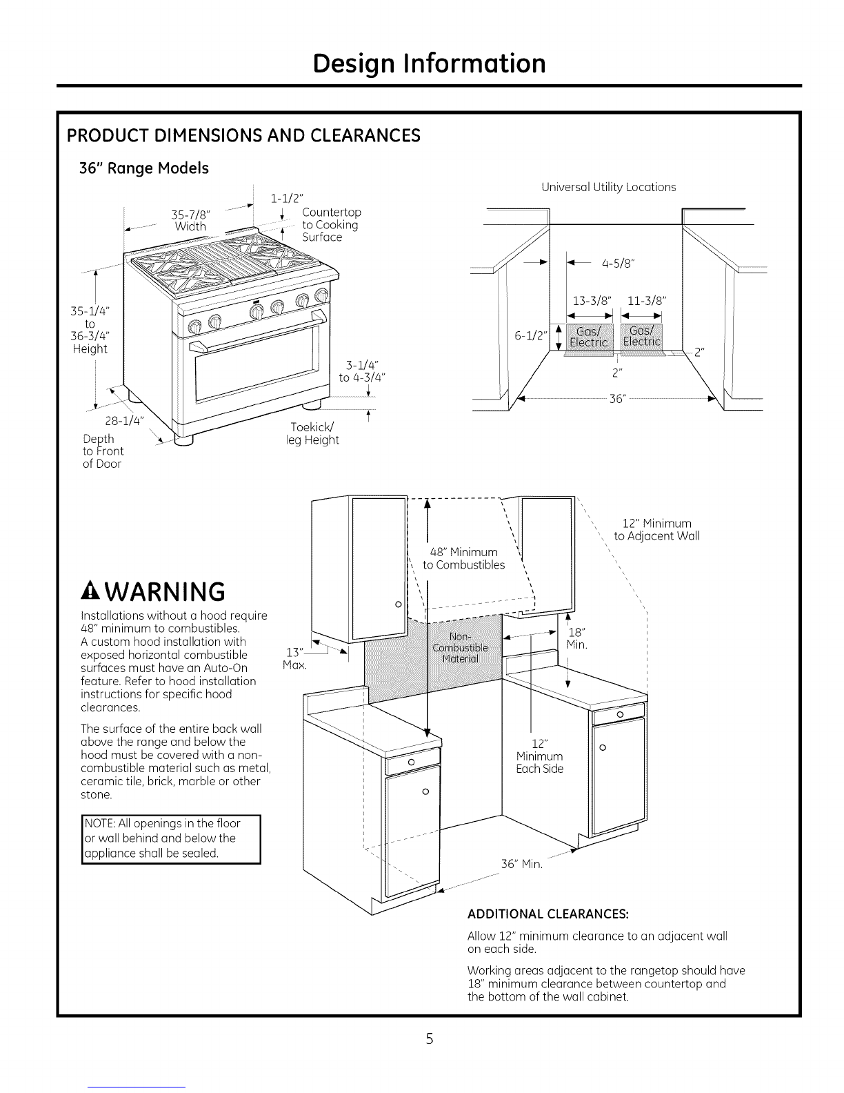
Product Dimensions and Clearances .......................4-7
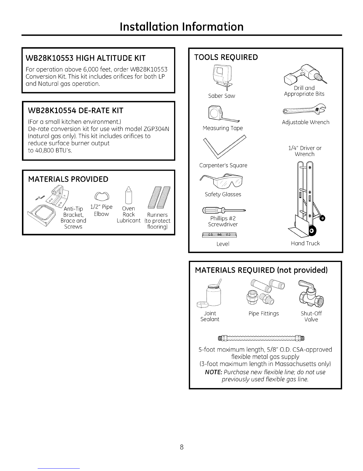
Tools and Materials Required .........................................8
Installation Preparation
Power Supply Locations .....................................................9
Installation Instructions
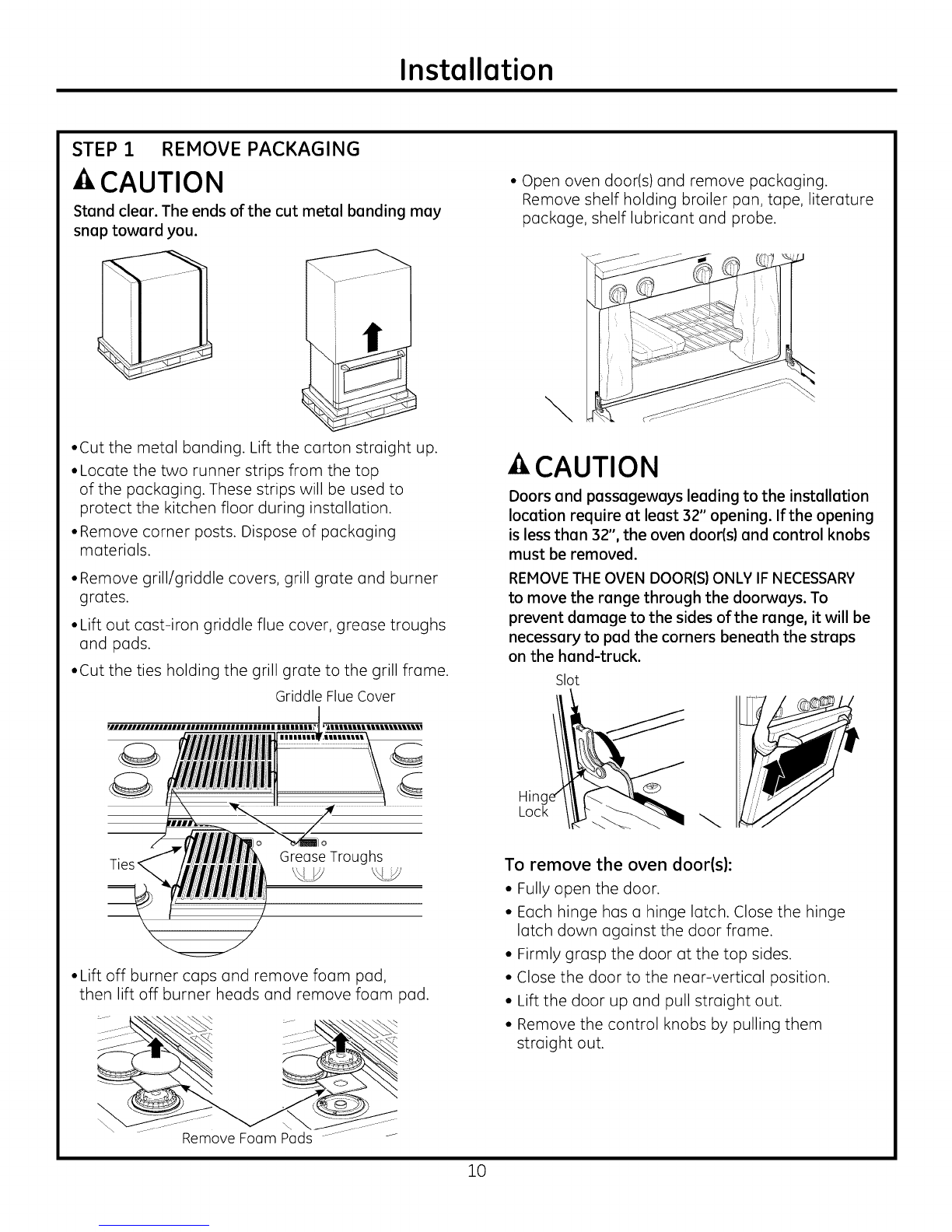
Step 1, Remove Packaging ..............................................10
Step 2, Move Range Indoors ...........................................11
Step 5, Install Anti-Tip Device .........................................12
Step 4, Connect Range to Gas .......................................15
Step 5, Connect Electrical .................................................15
Step
Step
Step
Step
Step
Step
6, Roll Range into Position ....................................14
7, Level the Range ....................................................15
8, Replace Oven Doors ............................................15
9, Check Burners ........................................................16
10, Check Operation of
Oven Bake Burners ...........................................16
11, Adjusting the Bake Burner
at Shutter ..............................................................16
Step 12, Check Operation of
Oven Broil Burner ..............................................17
Finalize Installation ..............................................................17
Installation Checklist ...........................................................17
Accessories ..............................................................................18
Accessory Installation ................................................19-21
Gas Conversion .............................................................22-26
MODELS AVAILABLE
These Monogram ranges are factory set for either
natural gas or LP gas. Order the model for your
installation situation.
48" Natural Gas Models:
ZGP484NG - 4 gas burners, grill and griddle
ZGP486NR - 6 gas burners and grill
ZGP486ND - 6 gas burners and griddle
48" LP Gas Models:
ZGP484LG - 4 gas burners, grill and griddle
ZGP486LR - 6 gas burners and grill
ZGP486LD - 6 gas burners and griddle
36" Natural Gas Models:
ZGP366N -6 gas burners
ZGP364NR - 4 gas burnersand grill
ZGP364ND - 4 gas burnersand griddle
36" LP Gas Models:
ZGP366L - 6 gas burners
ZGP364LR - 4 gas burners and grill
ZGP364LD - 4 gas burners and griddle
30" Natural Gas Model: ZGP304N
30" LP Gas Model: ZGP304L
BACKSPLASH ACCESSORIES
All models require 12" minimum clearance to a
vertical combustible surface at the rear. If clearance
is less than 12", the entire surface of the buck wall
above and the full width of the range must be
protected by u bucksplash. The backsplash must be
constructed of non-combustible material, such as
metal, ceramic tile, brick, marble or other stone.
Two Backsplash Accessories Available:
• The 12" high stainless steel backsplash accessory
is available. Use this backsplosh in combination
with a custom, non-combustible backsplash built
beyond the 12" height. The combined height of
the backsplash accessory and the custom
backsplash must reach the bottom of a hood,
or when there is no hood, to 48" above the
cooking surface.
•An adjustable 30" to 36" high backsplash with
shelf is also available. This bocksplash fills in the
space between the top of the range and the
bottom of the hood. The shelf is positioned so that
heat lamps from the bottom of o Monogram
professional hood are directed towards the shelf.
12" High Bocksplosh
ZX12B48PSS,for 48" wide ranges
ZX12B36PSS,for 36" wide ranges
ZX12B30PSS,for 30" wide ranges
30"to 36" Adjust(]ble Height
Bocksplosh With Shelf
ZXADJBA8PSS,for 48" wide r(]nges
ZXADJB36PSS,for 36" wide r(]nges
ZXADJB30PSS,for 30" wide ranges

Design Information
PRODUCT DIMENSIONS AND CLEARANCES
48" Range Models
Countertop
to Cooking
Surface
35-i/4"
to
36-3/4"
Height
28-1/4"
Depth
to Front
of Door
3-1/4"
to 4-3/4"
Toekick/ _'
leg Height
Universal Utility Locations
-AWARNING:
Installations without a hood require
48" minimum to combustibles.
Acustom hood installation with
exposed horizontal combustible
surfaces must have an Auto-On
feature. Refer to hood installation
instructions for specific hood
clearances.
The surface of the entire back wall
above the range and below the
hood must be covered with a non-
combustible material such as metal,
ceramic tile, brick, marble or other
stone.
NOTE:All openings in the floor I
or wall behind and below the I
app iance sha be sea ed.
--_,-
48" Minimum
to Combustibles
48" Hin.
\', 12" Minimum
', to Adjacent Wall
18"
Hin.
i
i
ADDITIONAL CLEARANCES:
Allow 12" minimum clearance to an adjacent wall
on each side.
Working areas adjacent to the rangetop should have
18" minimum clearance between countertop and
the bottom of the wall cabinet.

Design Information
PRODUCT DIMENSIONS AND CLEARANCES
36" Range Models
s5-7/8"
Width
1-1/2"
, Countertop
to Cooking
Surface
35-i/4"
to
36-3/4"
Height
28-1/4"
Depth
to Front
of Door
3-1/4"
to 4-3/4"
f
Toekick/
leg Height
Universal Utility Locations
4-s/8"
13-3/8" 11-3/8"
WARNING
Installations without a hood require
48" minimum to combustibles.
A custom hood installation with
exposed horizontal combustible
surfaces must have an Auto-On
feature. Refer to hood installation
instructions for specific hood
clearances.
The surface of the entire back wall
above the range and below the
hood must be covered with a non-
combustible material such as metal,
ceramic tile, brick, marble or other
stone.
NOTE:All openings in the floor I
or wall behind and below the I
app iance sha be sea ed.
....t..........
48" Minimum
to Combustibles
\', 12" Minimum
', to Ad acent Wall
\
i18"
Min.
I
36" Min.
ADDITIONAL CLEARANCES:
Allow 12" minimum clearance to an adjacent wall
on each side.
Working areas adJacent to the rangetop should have
18" minimum clearance between countertop and
the bottom of the wall cabinet.
5

Design Information
PRODUCT DIMENSIONS AND CLEARANCES
30" Wide Range Models
29-7/8" Width Countertop
,......... to Cooking
:i Surface
35-1/4"
to
36-314"
Height
28-1/4"
Depth
to Front
of Door
3-114"
to 4-314"
Toekick/ f
leg Height
to
Universal Utility Locations
4-5/8"
11-3/8" 7-3/8"
AWARNING
Installations without a hood require
48" minimum to combustibles.
A custom hood installation with
exposed horizontal combustible
surfaces must have an Auto-On
feature. Refer to hood installation
instructions for specific hood
clearances.
The surface of the entire back wall
above the range and below the
hood must be covered with a non-
combustible material such as metal,
ceramic tile, brick, marble or other
stone.
NOTE:All openings in the floor
or wall behind and below the
app iance sha be sea ed.
13"
Max.
30" Hin.
18"
Hin.
\
\\
\\ 12" Minimum
to Ad acent Wall
ADDITIONAL CLEARANCES:
Allow 12" minimum clearance to an adJacent wall
on each side.
Working areas adJacent to the rangetop should have
18" minimum clearance between countertop and
the bottom of the wall cabinet.

Design Information
PRODUCT DIMENSIONS AND CLEARANCES
48% 36" and 30" Range Models
i0-i/2" = .............................im-
13/16" m- 4
A
Optional 30-36" 12"
Backs@ash A
Accessories
i-i/2"
3s-zI4"
to
36-3/4"
V
12" Hin. to combustibles or 0" to
a non-combustible material above
the cooking surface
28-7/8"
To Front
Edge
3-3116"
Control Panel
Depth I_
28-1/4" To
Beveled
Edge of Control
Panel Bullnose
27-1/2" To
Beveled Edge
- Haximum
Adjacent
Cabinet Depth
for
Flush
Installation
28-i/4"
To Front of
4 Door I_
31-i/16"
i4t To Front of
Handle
i4
i
p.
7" Control
Panel Height
i
i
m
|
........................... --In J
J
ij
48-i/4"
With Oven Door
Open
D,-
- WARNING
The 12" high stainless steel
backsplash accessory must be
installed in combination with a
custom non-combustible backs@ash.
The finished backsplash must cover
the entire back wall up to the bottom
of a hood, or when there is no hood,
48" to combustibles.

Installation Information
WB28K10553 HIGH ALTITUDE KIT
For operation above 6,000 feet, order WB28K10553
Conversion Kit. This kit includes orifices for both LP
and Natural gas operation.
WB28K10554 DE-RATE KIT
(For a small kitchen environment.)
De-rate conversion kit for use with model ZGPBO4N
(natural gas only). This kit includes orifices to
reduce surface burner output
to/40,800 BTU's.
MATERIALS PROVIDED
1/2" Pipe
Elbow
'd
Oven
Rack Runners
Lubricant (to protect
flooring)
TOOLS REQUIRED
Saber Saw
Measuring Tape
Carpenter's Square
Safety Glasses
Phillips#2
Screwdriver
Drill and
Appropriate Bits
Adjustable Wrench
i/4" Driver or
Wrench
Level Hand Truck
MATERIALS REQUIRED (not provided)
Joint Pipe Fittings Shut-Off
Sealant Valve
5-foot maximum length, 5/8" O.D. CSA-approved
flexible metal gas supply
(3-foot maximum length in Massachusetts only)
NOTE: Purchase new flexible line; do not use
previously used flexible gas line.

Installation Preparation
POWER SUPPLY LOCATIONS
Gas Supply:
•The natural gas models are designed to operate at
S" water column pressure. For proper operation, the
pressure of the natural gas supplied to the regulator
must be between 7" and 13" water column.
•The LP models are designed to operate at 10" water
column pressure. For proper operation, the pressure
of the LP gas supplied to the regulator must be
between 11" and 13" water column.
•Locate the pipe stub on the back wall or floor as
illustrated in "Dimensions and Clearances." Use
S-foot maximum length, 5/8" O.D. flexible gas supply
line (3-foot in Massachusetts).
Electric Supply:
Your range must be electrically grounded in
accordance with local codes, in accordance with
National Electrical Code (ANSI/NFPA 70, latest
edition). In Canada, electrical grounding must be in
accordance with the current CSA C22.1 Canadian
Electrical Code Part 1. See Electrical Connections in this
section.
-4,CAUTION
Do not attempt to operate the oven if this range of
this range during a power failure.

Installation
STEP 1 REMOVE PACKAGING
CAUTION
Stand clear. The ends of the cut metal banding may
snap toward you.
•Cut the metal banding. Lift the carton straight up.
•Locate the two runner strips from the top
of the packaging. These strips will be used to
protect the kitchen floor during installation.
•Remove corner posts. Dispose of packaging
materials.
•Remove grill/griddle covers, grill grate and burner
grates.
•Lift out cast-iron griddle flue cover, grease troughs
and pads.
•Cut the ties holding the grill grate to the grill frame.
Griddle FlueCover
GreaseTroughs
•Lift off burner caps and remove foam pad,
then lift off burner heads and remove foam pad.
• Open oven door(s) and remove packaging.
Remove shelf holding broiler pan, tape, literature
package, shelf lubricant and probe.
\
-4,CAUTION
Doors and passageways leading to the installation
location require at least 32" opening. If the opening
is less than 32", the oven door(s) and control knobs
must be removed.
REMOVETHE OVEN DOOR(S)ONLY IF NECESSARY
to move the range through the doorways. To
prevent damage to the sides of the range, it will be
necessary to pad the corners beneath the straps
on the hand-truck.
Slot
Hin(
Lock
To remove the oven door(s):
• Fully open the door.
• Each hinge has a hinge latch. Close the hinge
latch down against the door frame.
• Firmly grasp the door at the top sides.
• Close the door to the near-vertical position.
• Lift the door up and pull straight out.
• Remove the control knobs by pulling them
straight out.
Remove Foam Pods
10

Installation
STEP 2 MOVE THE RANGE INDOORS
1 Tilt the range forward on the skid.
__Toekick
2 Lift the toekick out of the foam base.
4 Attach the hand-truck straps around the unit.
IMPORTANT: Place the hand-truck straps below
the oven door handles. To avoid damaging the
side panels, place a pad between the hand-truck
and the range.
5 Tilt the range to lower the hand-truck wheels
off the skid.
Hand-Truck
Strops Below
Oven Door
Handles
/ _i_iii¢_i¢,_i_
3 Drive the blade of the hand-truck beneath
the foam block.
6 Place the appliance runners on the floor
at the left and right sides in front of the opening.
IMPORTANT: The runners provide a surface for
rolling the range into the final oosition and will
protect the floor finish. The runners must be
removed before leveling the range.
7 IVlove the range indoors. Position the range
in front of the installation location, onto
the runners.
Insert Blade Under
the Foam Block
You may need to remove the
front of the foam block to fit
through the doorway.
IMPORTANT: Do not remove the base foam
block while the hand-truck is in use. Place
the hand-truck blade underneath the base
foam block and transport the range to the final
location.
11

Installation
STEP 3 INSTALL ANTI-TIP DEVICE
•All ranges can tip.
• BURNSor other SERIOUSINJURIES
can result.
INSTALLand CHECKthe ANTI-TIP
bracket following these instructions.
To reduce the risk of tipping the range, the range must
be secured by a properly installed anti-tip bracket. See
installation instructions shipped with the bracket
for complete details before attempting to install.
To check if the bracket is installed and engaged properly,
look underneath the range. The anti-tip bracket should
be inserted into the opening on the anti-tip brace on the
range. If the bracket arm misses the brace to the left or
right, or the bracket arm is not protruding through the
brace opening, the bracket must be reinstalled.
If the range is pulled from the wall for any reason, always
repeat this procedure to verify the range is properly
secured by the anti-tip bracket.
If your range has no anti-tip bracket, call 1.800.626.8774
to receive one at no cost.
Ifthe anti-tip device supplied with the range does not fit this
application, use the universal Anti-Tip Device WB2X7909.
Read the AHAI Anti-Tip Safety Brochure packed with
the bracket.
Anti-Tip Parts Provided
4 Wood Screws Anti-Tip Bracket
3 Hex Head Screws
(2 required, 1 extra)
??
?Anti-Tip Brace AHAM Anti-Tip
Safety Brochure
• Attach the anti-tip bruce onto the bottom of the
range in the recessed area. Install 2 hex screws
(provided) through the brace and into the range.
NOTE: This anti-tip device may be installed on the
opposite side of the range.
_e
Hex Screws
Anti-Tip Brace
Alternate Brace
Position
• Measure and mark Dimension A (see table below)
from the left (or right) side of the installation
location. If the countertop has an overhang,
add that dimension to Dimension A.
• Place the anti-tip bracket against the floor and
back wall at the marked location. Hark screw holes
for fastening the bracket to the wall sole plate and
the floor.
• Drill 1/8" pilot holes at a 20° angle.
• Secure the bracket to the wall and/or floor with
at least 2 wood screws (provided).
For Concrete or Cement Construction: You must
use appropriate fastening hardware (not provided).
Range
30"
36"
48"
I
A I Anti-Tip Bracket
5-1/16"_
5-1/16" e
8-1/4"
12

Installation
STEP4 CONNECT RANGE TO GAS
AWARNING
Do not use a flame to check for gas leaks.
Assure that gas supply is turned off at the
shut-off valve:
•Apply pipe thread sealant to the gas inlet located
at the back of the range. Install the 1/2" pipe
elbow (provided) to the gas inlet.
• Connect 5/8" O.D. flexible metal connector to
gas inlet. Connect the other end of the flexible
connector to the house gas supply.
• Turn on the gas and check for leaks:
- Use a liquid leak detector at alljoints
and connections in the system.
or,
IMPORTANT: Disconnect the range and the
individual shut-off valve from the gas supply piping
system during any pressure testing of that system
at test pressures greater than 1/2 psig. Isolate the
range from the gas supply piping system by closing
the individual manual shut-off valve to the range
during any pressure testing of the gas supply piping
system at test pressures equal to or less than
1/2 psig.
NOTE: This range is equipped with a gas shut-off
valve located on top of the range, beneath the rear
vent. This shut-off valve is to be used in the event
that service is required in the future.
STEP 5 CONNECT ELECTRICAL
Electrical Requirements
120-volt, 60 Hertz, properly grounded dedicated
circuit protected by a 15-amp or 20-amp circuit
breaker or time delay fuse.
STEP 5 CONNECT ELECTRICAL (Cont.}
Extension Cord Cautions
Because of potential safety hazards associated
with certain conditions, we strongly recommend
against the use of an extension cord. However, if you
still elect to use an extension cord, it is absolutely
necessary that it be a UL-listed, 3-wire grounding-
type appliance extension cord and that the current
carrying rating of the cord in amperes be equivalent
to, or greater than, the circuit rating.
Grounding
IMPORTANT--IPlease read carefully)
FOR PERSONAL SAFETY, THIS APPLIANCE MUST BE
PROPERLY GROUNDED.
Preferred Method
Ensure proper ground
exists before use
The power cord of this appliance is equipped with
a three-prong (grounding) plug which mates with a
standard three-prong grounding wall receptacle to
minimize the possibility of electric shock hazard from
this appliance.
The customer should have the wall receptacle and
circuit checked by a qualified electrician to make
sure the receptacle is properly grounded.
Where a standard two-prong wall receptacle is
encountered, it is the personal responsibility and
obligation of the customer to have it replaced with a
properly grounded three-prong wall receptacle.
DO NOT, UNDER ANY CIRCUMSTANCES, CUT OR
REMOVE THE THIRD (GROUND) PRONG FROM THE
POWER CORD.
A word about GFCI's - GFCI's are not required or
recommended for gas range receptacles.
Ground Fault Circuit Interrupters (GFCI's) are devices
that sense leakage of current in a circuit and
automatically switch off power when a threshold
leakage level is detected. These devices must be
manually reset by the consumer. The National
Electrical Code requires the use of GFCI's in kitchen
receptacles installed to serve countertop surfaces.
Performance of the range will not be affected if
operated on a GFCI-protected circuit
but occasional nuisance tripping of the GFCI breaker
is possible.
13

Installation
STEP 5 CONNECT ELECTRICAL(Cont.)
A. Usage Situations where Appliance Power Cord
will be Disconnected Infrequently.
An adapter may be used only on a 1S-amp circuit.
Do not use an adapter on a 20-amp circuit. Where
local codes permit, a TEMPORARY CONNECTION
may be made to a properly grounded two-prong
wall receptacle by the use of a UL-listed adapter,
available at most hardware stores. The larger slot in
the adapter must be aligned with the larger slot in
the wall receptacle to provide proper polarity in the
connection of the power cord.
Temporary Method
(Adapterplugsnot permitted inCanada)
Align large prongs/slots
Ensure proper
ground and firm
connection before
use
-4,CAUTION: Attaching the adapter ground
terminal to the wall receptacle cover screw does not
ground the appliance unless the cover screw is metal,
and not insulated, and the wall receptacle is grounded
through the house wiring. The customer should have
the circuit checked by a qualified electrician to make
sure the receptacle is properly grounded.
When disconnecting the power cord from the
adapter, always hold the adapter with one hand.
If this is not done, the adapter ground terminal is
very likely to break with repeated use. Should this
happen, DO NOT USEthe appliance until a proper
ground has again been established.
STEP 6 ROLL RANGE INTO POSITION
-4,WARNING
The Anti-Tip Bracket must be properly installed to
prevent tipping of the range. Failure to do so can
cause serious damage or injury.
• Check to be sure the appliance runners are
beneath the wheels.
• The range is shipped with the wheels in the down
position. Carefully roll the range into position,
being careful not to entangle or pinch the power
cord and flexible gas tubing.
• Remove the runners beneath the range.
u
Be sure Anti-Tip
Bracket isengaged
with the brace on
the range.
14

Installation
STEP 7 LEVEL THE RANGE
WARNING
The range must be level and be supported by the
legs-not the wheels. The range could move if the
wheels make contact with the floor. Be sure all legs
make contact with the floor in any installation.
•All legs must be leveled after the product is
installed.
•Check to be sure the adjoining cabinets/
countertops are level, front to back and left to right
across the opening of the range.
•Measure the distance from the floor to the top of
the countertop in the left and right rear corners.
•Adjust the height of the range to countertop height
or higher.
IMPORTANT: This range should always be installed
at countertop height or higher. DO NOT INSTALL
THE RANGE LOWER THAN ADJACENT COUNTERTOP
HEIGHT. The range must be supported by all 4 legs,
regardless of countertop height.
FRONT LEG ADJUSTMENT
•Slide front cylinders up to adjust front leveling legs.
Be careful not to damage cylinder.
•A leveling leg wrench is supplied. Reach under the
front of the range near the right side. Locate and
remove a thumb screw, then slide wrench out of
the slot.
Thumb Screw
Slide leg
cylinder up.
• Use the supplied wrench to turn the front leveling
legs. Turn clockwise to raise the range above the
wheels. Turn counterclockwise to lower the legs.
• Be sure to return the wrench to its storage slot for
future use.
IS
STEP 7 LEVEL THE RANGE (cont.}
REAR LEG ADJUSTMENT
• Remove two screws from rear vent trim. Slide vent
trim forward, then lift up to remove.
• Find the two rear leg extension rods. Use o 1/4" driver
or wrench to adjust the left or right rear legs.
Rear Vent Trim
Rear Leg
Extension Rod
• Replace the rear vent trim using the original screws.
STEP 8 REPLACE OVEN DOORIS}
Skip this step if oven doors are in place.
IMPORTANT: Do not lift the door by the handle.
To replace the oven doors:
• Firmly grasp the door at the top sides. This is
critical.
• Approach the range with the door angled in a
vertical position.
• Guide the hinges into the slots.
• Push the door in firmly while opening.
• Once in position, open the door completely. Push
the hinge locks back in and toward the front
frame.
-ACAUTION: Take cure when replacing
the oven doors. If the hinge latch is not securely
locked, the hinge may snap back and separate. If
the hinge separates, you must apply pressure
(possibly with your foot) to press it back together
and then engage the hinge latch.

Installation
STEP9 CHECK BURNERS
Check to be sure that burner heads and caps
are securely seated.
Burner Cap Properly Seated
Burner Cap Not Properly Seated
•Check for proper ignition:
- Push in one control knob and turn to LITE
position.
- The igniter will spark and the burner will light; the
igniter will cease sparking when the burner is lit.
- First test may require some time, while air is
flushed out of the gas line.
- Turn knob to OFF.
- Repeat the procedure for each burner.
IMPORTANT: If the igniter electrodes continue to
spark after the burners are lit, check that each
burner component is assembled properly. Refer to
the Owner's Manual.
•Burner flames should be blue and stable with no
yellow tips, excessive noise or lifting of the flame
from the burner. If any of these conditions exist,
check that the burner ports are not blocked. If one
of these conditions continues, cull for service.
STEP 10 CHECK OPERATION OF OVEN
BAKE BURNERS
A.
B.
Remove the oven bottom and diffuser (refer to
sections 6A & B of the conversion installation
instructions, page 24).
To operate the Bake burner, turn the Oven Mode
Selector knob to Bake and turn the Oven Tem-
perature Knob to 350. After 30 to 90 seconds,
the burner will ignite.
Flames should be steady, approximately 1" blue
cones and, if range is supplied with natural gas,
should burn with no yellow tips. With most LP
gas, small yellow tips at the end of the outer gas
cones ore normal. The inner cone of the flame
should be 1/2" to 3/4" long for either gas.
C. Perform the same check on the companion oven
if present.
16
STEP II ADJUSTING THE BAKE BURNER
AT SHUTTER (If necessary)
To adjust the shutter:
1. If the flames ore yellow, open the air shutter
more than the original setting.
2. If the flames blow away or flutter from the
burner, close the air shutter more than the
orignol setting.
The air shutter for the bake burner is access-
able by removing the burner.
A. Using o screwdriver, loosen the air shutter
adjustment screw.

Installation
STEP 11 ADJUSTING THE BAKE BURNER
AT SHUTTER (Cont.)
B. Hake the air shutter adjustment.
C. Retighten the air shutter screw.
D. Check that the inner cone of the flame is
between 1/2" and 3/4" (12.7 mm and
19.1 mm)long.
After confirming correct burner operation,
replace oil ports.
STEP 12 CHECK OPERATION OF OVEN
BROIL BURNER
The broil burner must be on and warmed up for 3
min. prior to checking operation.
1. To operate the Broil burner, turn the Oven IVlode
Selector knob to Broil and turn the Oven Tem-
perature Knob to Broil Hi. After 30 to 90 sec-
onds, the burner will ignite.
There should be on even blanket of flame cover-
ing the entire surface of the screen that is blue
and barely visible, approximately 1/4" long. After
approximately 3 min., the screen area should
begin to glow orange.
................. JJ_i
2. Perform the some check on the companion oven
if present.
If the flame is long and lazy, verify the proper
orifice is installed and the regulator is converted
properly for your gas supply.
FINALIZE INSTALLATION
Place the burner grates over the burners.
The grates should be seated and should not rock.
The griddle is secured with screws. It is designed
to be stationary and should not be removed.
The griddle has two leveling screws beneath
the rear flue cover that con be used to adJust
to the desired slope.
Griddle Flue Cover
_Leveling Screws
The two inner screws ore clamping screws
for securing the griddle in place. Loosen these two
screws before leveling. Do not remove these two
screws.
The two outer screws ore leveling screws. Do not
remove these two screws. They con be turned to
level the griddle or to provide o forward slope to
help grease and oils drain away from the food
being cooked.
After leveling the griddle, hand-tighten the
clamping screws; do not over-tighten.
17
INSTALLATION CHECKLIST
•Make sure oll controls ore left in the OFF position.
• IVlokesure the flow of combustion and ventilation
air to the range is unobstructed.
•Recheck Steps:
Double check to make sure everything in this
manual has been completed. Rechecking steps
will ensure safe use of the range.
NOTE:The rating plate is located on the bottom of
the control panel and is visible when the oven door is
opened. The model and serial number is behind the
left knob and is visible when the knob is pulled off.

Installation
ACCESSORIES--TOEKICK (provided)
•lnstoll the toekick ofter the ronge hos been leveled.
•Meosure the distonce between the floor ond the
bottom of ronge.
•Loosen the two screws on eoch end. Adjust the
toekick height by sliding the upper ond lower pieces
oport to 1/8" less thon the meosured height.
•Secure the top ond bottom sections by tightening
the 2 screws on eoch end.
• Push toekick ogoinst ronge leg until clip snops
to legs.
NOTE: Be sure the toekick snaps securely to the leg.
Top of
Toekick
Bottom
of Toekick /
Screw
Push
Push
18

ZX12B30PSS, ZX12B36PSS, ZX12B48PSS Accessory Installation
OPTIONAL ACCESSORIES--12" HIGH BACKSPLASH
AWARNING:
To prevent ignition of combustible materials,
the entire back wall above the range must
be protected by a bocksplosh constructed
of non-combustible material.
This stainless steel backsplash accessory
must be installed in combination with a custom,
non-combustible backsplash built beyond
the 12" height of the bocksplosh.
BEFORE YOU BEGIN
Read these instructions completely
and carefully.
IMPORTANT: Save these instructions for local
inspector's use.
IMPORTANT: OBSERVE ALL GOVERNING CODES
AND ORDINANCES.
NOTE TO INSTALLER: Be sure to leave these
instructions with the Consumer.
NOTE TO CONSUMER: Keep these instructions
with your Owner's Manual for future reference.
This kit provides for the installation of a 12"
high backsplash for 30", 36" or 48" Monogram
Professional Ranges and Rangetops.
TOOLS AND MATERIALS REQUIRED
•Gloves to protect against sharp edges
•T-15 and #2 Phillips screwdrivers
• Drill with 3/32" and 9/64" bits
•Safety glosses
• Level
•Pencil
Wall Support
Panel
This Kit Includes
•Wall support panel
•Cover panel
• Hardware package with
- 5 Stainless Steel Torx 15 #8
self-tapping screws
- 5 Phillips #2 pan head wood
#10 screws
Hardware
Package
INSTALL 12" BACKSPLASH
-AWARNING: Thisbocksploshmust
be securelyfastenedtothe wall.Failuretodo
so couldresultindamage or personalinjury.
• Installand leveltherangeorrangetopand
therange hood accordingtotheinstallation
instructions.
• Remove the backsplash packaging and
protective film.
• Use a level to pencil a horizontal line on the wall,
1/8" above the range or rangetop. The 1/8" gap
allows the cover panel to overlap the wall support
panel.
• Locate wall studs on each side. Where studs are not
available, plan to use wall anchors (not provided).
• Align the wall support panel on the marked
horizontal line and centered left to right.
• The wall support panel must be secured to the wall
at all 4 corners. Use wood screws (provided) or wall
anchors (not provided) to secure the support panel
to the wall.
Place the cover panel over the wall support panel
and secure with Torx screws (provided). Install 2
screws on each side.
Install 4
Wood Screws Support
Panel
Wall
Support
Panel
Cover Panel
"°.'_'7Install T-15
o_" Screws
19

ZXADJB30PSS,ZXADJB36PSS,ZXADJB48PSSAccessory Installation
ACCESSORIES--30" TO 36" ADJUSTABLE BACKSPLASH (not included)
WARNING:
To prevent ignition of combustible materials,
the entire back wall above the range must be
protected by a backsplash constructed of non-
combustible material.
BEFOREYOU BEGIN
Read these instructions completely
and carefully.
IMPORTANT: Save these instructions for local
inspectoCs use.
IMPORTANT: OBSERVEALL GOVERNING CODES
AND ORDINANCES.
NOTE TO INSTALLER: Be sure to leave these
instructions with the Consumer.
NOTE TO CONSUMER: Keep these instructions
with your Owner's Manual for future reference.
• This backsplash adjusts to fit the space between
the top of the range and the bottom of the hood,
from 30" Min. to 36" Max. height.
• Maximum shelf load-bearing weight is 40 Ibs.
TOOLS AND MATERIALS REQUIRED
•Gloves to protect against sharp edges
•T-15 and #2 Phillips screwdrivers
• Drill with 3/32" and 9/6/4" bits
•Safety glasses
• Level Top
• Pencil with Shelf
Top Wall
Support
This Kit Includes
•Top wall support
•Bottom wall support
•Top cover with shelf
• Bottom cover
• Hardware package with
- 9 Stainless Steel Torx 15 #8
self-tapping screws
- 9 Phillips #2 pan head wood #10 screws
- 3 Stainless Steel #2 truss head
#10 screws (for alternate
installation method)
Bottom Wall Support
Hardware
Package
INSTALL THE WALL SUPPORT PANELS
WARNING: The wall support panels must
be securely fastened to the wall. Failure to do so
could result in damage or personal injury.
IMPORTANT:Thisbacksplash isdesignedto cover the wall
between the bottom of the hoodand the top of the range.
Thevent hood should be installed over the rangetop or
range before installing this backsplash.
• Installand levelthe Range/Rangetop according to the
product installation instructions.
• Removebacksplash packaging and protective film.
• Locatewall studs on each side.Where studs are not
available, plan to usewall anchors (notprovided).
• Usea levelto pencil 2 horizontal lineson the wall, one
1/8" below the vent hood and the other 1/8" abovethe
Range/Rangetop.This 1/8" space allows the cover panels
to overlapthe wall supports.
• Securethe top wall support panel to the wall with/4 wood
screws,through the outermost studs.
• Use/4wood screws to securethe bottom wall support
panel.Thecenter slot should be positioned at the top.
Thegap between the top and bottom support panelswill be
covered bythe top cover with shelf.
Secure the
top panel to
the wall with/4
wood screws
Wood
Wood
Screws Secure the
bottom panel
to the wall
with/4 wood
screws
20
This manual suits for next models
13
Table of contents
Languages:
Other GE Range manuals