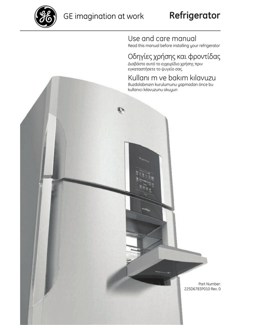
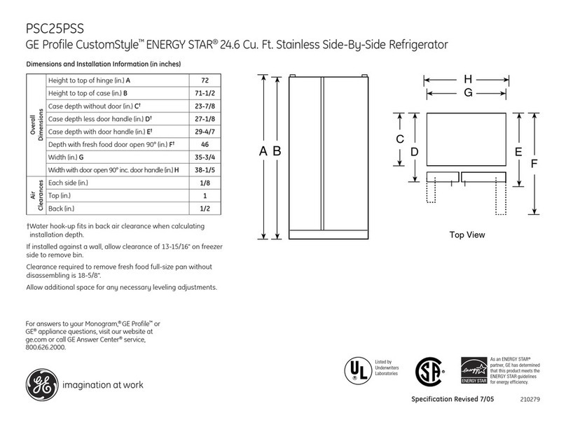
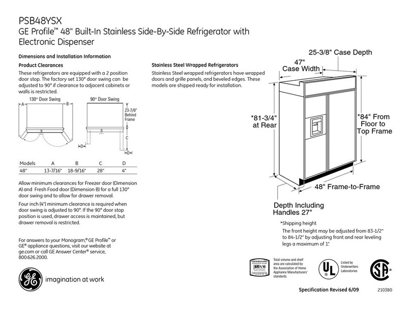
GE Monogram ZIC360NXRH User manual

Design Guide with
Installation
Instructions
36”Built-In Bottom-Freezer
Refrigerators
monogram.com
Pub. No. 49-60468-3
Part No. 224D3095P001
08-13 GE

Safety Information
Skill Level³ Installation of this refrigerator requires
basic mechanical, carpentry and plumbing skills.
Proper installation is the responsibility of the installer.
Product failure due to improper installation is not
covered under the GE Appliance Warranty. See the
Owner’s Manual for warranty information.
WARNING:
7KHVHUHIULJHUDWRUVDUHWRSKHDY\DQGPXVW
be secured to prevent the possibility of tipping
IRUZDUG$QWL7LSSURWHFWLRQLVUHTXLUHG6HHSDJH
for details.
8VHWKLVDSSOLDQFHRQO\IRULWVLQWHQGHGSXUSRVH
,PPHGLDWHO\UHSDLURUUHSODFHHOHFWULFVHUYLFHFRUGV
that become frayed or damaged.
8QSOXJWKHUHIULJHUDWRUEHIRUHFOHDQLQJRUPDNLQJ
repairs.
5HSDLUVVKRXOGEHPDGHE\DTXDOLILHGVHUYLFH
technician.
AVERTISSEMENT
&HVUpIULJpUDWHXUVVRQWORXUGVHQKDXWHWLOIDXW
OHVDUULPHUSRXUpYLWHUOHXUEDVFXOHPHQW,OIDXWDYRLU
un système de protection contre le renversement.
9RLUOHVGpWDLOVSDJH
,OQHIDXWXWLOLVHUFHWDSSDUHLOTXHSRXUO·XWLOLVDWLRQ
DSSURSULpH
5pSDUHURXUHPSODFHULPPpGLDWHPHQWWRXWFRUGRQ
pOHFWULTXHHIILORFKpRXHQGRPPDJp
,OIDXWGpEUDQFKHUOHUpIULJpUDWHXUDYDQWOHQHWWR\DJH
ou toute intervention.
/HVUpSDUDWLRQVGRLYHQWrWUHIDLWHVSDUXQWHFKQLFLHQ
TXDOLILp
For Monogram local service in your area, call
1.800.444.1845.
For Monogram service in Canada, call
1.800.561.3344
For Monogram Parts and Accessories, call
1.800.626.2002.
www. monogram.com
2
BEFORE YOU BEGIN
Read these instructions completely and carefully.
IMPORTANT³ Save these instructions
for local inspector’s use. Observe all governing codes
and ordinances.
Note to Installer³Be sure to leave these
LQVWUXFWLRQVZLWKWKH&RQVXPHU
Note to Consumer³ Keep these instructions
with your Owner’s Manual for future reference.
WARNING:
7KLVDSSOLDQFHPXVWEHSURSHUO\JURXQGHG6HH
“Grounding the Refrigerator,” page 9.
AVERTISSEMENT
&HWDSSDUHLOGRLWrWUHFRUUHFWHPHQWPLVjODWHUUH
&RQVXOWHU© 0LVHjODWHUUHGXUpIULJpUDWHXU ªSDJH
If you received a damaged refrigerator, you should
immediately contact your dealer or builder.
CAUTION:
Due to the weight and size of this refrigerator, and to
reduce the risk of personal injury or damage to the
SURGXFW³7+5((3(23/($5(5(48,5(')253523(5
,167$//$7,21
PRUDENCE
FDXVHGXSRLGVHWGHODWDLOOHGHFHUpIULJpUDWRUHW
SRXUUpGXLUHOHULVTXHGHEOHVVXUHHWGHGRPPDJHV,/
)$87752,63(56211(63285)$,5(/·,167$//$7,21
&255(&7(0(17
CONTENTS
Planning Guide
7KH,QVWDOODWLRQ6SDFH..............................3
'LPHQVLRQVDQG&OHDUDQFHV .................3
130° Door Swing.........................................4
90° Door Swing............................................ 5
&XVWRPL]DWLRQ%DVLFV ............................... 6
Panel Dimensions.......................................7
Side Panels .................................................... 8
=8**ULOOH3DQHO'LPHQVLRQV..............8
Installation Instructions
7RROV+DUGZDUH0DWHULDOV....................9
Grounding the Refrigerator................... 9
Step 1, Remove Packaging................. 10
6WHS,QVWDOO:DWHU/LQH..................... 10
6WHS$52:DWHU/LQH ........................ 11
Step 3, Install Side Panels.................... 11
6WHS,QVWDOO$QWL7LS%UDFNHWV........ 11
6WHS/HYHO5HIULJHUDWRU.................... 12
Step 6, $OWHUQDWH$QWL7LS3URFHGXUH... 12
Step 7, Secure Refrigerator to
&DELQHWU\ ..................................... 12
Step 8, Adjust Door Swing................... 13
Step 9, Install Grille Panel.................... 13
Step 10, Install Framed Panels ......... 14
Step 10A, Install Overlay Panels....... 15
6WHS&RQQHFW:DWHU6XSSO\ ....... 16
6WHS&RQQHFW3RZHU....................... 16
Step 13, Start Icemaker........................ 16
6WHS,QVWDOO7RHNLFN ......................... 17
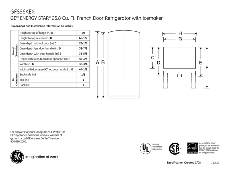
36" Frame to
Frame Width
*84" From
Floor to
Top Frame
35"
Case Width
*83-1/2"
at
Rear
25-3/8" Framed Models
25-3/4" Stainless Steel Models
Case Depth
Depth Including Handles:
26-7/8" Framed Models
27-3/4" Stainless Steel Models
28-11/16" Professional Style Models
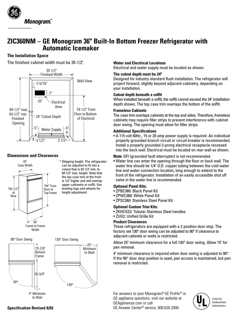
THE INSTALLATION SPACE
Water And Electrical Locations
Electrical and water supply must be located as shown.
The cutout depth must be 24”
7KHUHIULJHUDWRUZLOOSURMHFWIRUZDUGVOLJKWO\EH\RQG
adjacent cabinetry, depending on your installation.
Allow minimum 1/8” air gap between case back & wall.
Cutout depth beneath a soffit:
When installed beneath a soffit, the soffit cannot exceed
the 24”LQVWDOODWLRQGHSWKVKRZQ7KHWRSFDVHWULP
overlaps the bottom of the soffit.
Additional Specifications
$YROW+]RUDPSSRZHUVXSSO\LVUHTXLUHG
An individual properly grounded branch circuit or circuit
breaker is recommended. Install
a properly grounded 3-prong electrical receptacle
recessed into the back wall. Electrical must be located
on rear wall as shown.
Note: GFI (ground fault interrupter) is not recommended.
:DWHUOLQHFDQHQWHUWKHRSHQLQJWKURXJKWKHIORRU
RUEDFNZDOO5RXWH*(6PDUW&RQQHFW™kit or 1/4”O.D.
copper tubing between the cold water line and the
ZDWHUFRQQHFWLRQORFDWLRQ7KHWXELQJVKRXOGEH
long enough to extend to the front of the refrigerator.
Installation of an easily accessible shut-off valve in the
water line is required.
DIMENSIONS AND CLEARANCES
6KLSSLQJKHLJKW7KH
refrigerator can be
adjusted to fit into a
cutout that is 83-1/2”
min. to 84-1/2”max.
height. Note that the top
case trim at the front is
1/2”higher and will
overlap upper cabinetry
RUVRIILW8VHOHYHOLQJ
legs and wheels for a
maximum 1”height
adjustment.
Product Clearances
7KHVHUHIULJHUDWRUVDUHHTXLSSHGZLWKDSRVLWLRQGRRU
VWRS7KHIDFWRU\VHWGRRUVZLQJFDQEHDGMXVWHGWR
90° if clearance to adjacent cabinets or walls is restricted.
3
6"
Wall View
Electrical
Area
84-1/2" max
83-1/2" min
Finished
Opening
75" From
Floor to
Bottom
of Electrical Area
10"
24" Cutout Depth
35-1/2"
Finished Width
2-5/16"
5"
10"
10"
3-1/2" 3-1/2"
5"
3-1/2"
Water Supply
ZUG2, ZUGSS2 Unified Grille Panel Kit
,I\RXDUHLQVWDOOLQJWZRUHIULJHUDWRUVVLGHE\VLGH
the installation space must be 71-1/2”wide.
Note: Additional cutout width may be required when side
panels are used. Add side panel thickness to the finished
cutout to calculate rough-in width.
7KHZDWHUDQGHOHFWULFDOORFDWLRQVIRUHDFKSURGXFW
must be located as shown.
$VHSDUDWH9+]RUDPSSRZHUVXSSO\LV
recommended for each product.
7KHILQLVKHG
cutout width
must be
35-1/2”.
Allow 25”minimum clearance for a full 130° door
swing. Allow 15”for pan removal.
For a 90° door swing, allow 4”min. clearance to a wall,
for framed and stainless steel models. Allow 5”min.
clearance for professional style models. If the 90° door
stop position is used, pan access is maintained, but pan
removal is restricted.
See illustrations pages 4 and 5 to determine door swing
interaction with adjacent cabinets or countertops.
Design Guide

1/4" 1/2" 3/4" 1" 1-1/4"
1"
3/4" Overlay
Panel
(Nominal Size)
Stainless Steel
1/4"
1/2"
3/4"
2"
1-1/4"
1-1/2"
1-3/4"
3"
2-1/4"
2-1/2"
2-3/4"
1/4"
1/2"
3/4"
Door
23-7/8" From
Rear of
Refrigerator
1"
Refrigerator
Case
Trim
Top View
130° DOOR SWING
(factory setting)
Scale 1:1
4
Frameless Cabinets: 7KHFDVHWULP
overlaps cabinets at the top and sides.
7KHUHIRUHIUDPHOHVVFDELQHWV
may require filler strips to prevent
interference with cabinet door swing.
7KHRSHQLQJPXVWDOORZIRUILOOHUVWULSV
Design Guide

1/4"
1/2"
3/4"
1"
1-1/4"
1/4"
1/2"
3/4"
1"
1-1/4"
1-1/2"
23-7/8"
From Rear of
Refrigerator
3/4" Overlay
Panel
(Nominal Size)
Case Trim
Refrigerator
Door
Stainless Steel
5
Top View
90° DOOR SWING
(optional setting)
Scale 1:1
Frameless Cabinets:
7KHFDVHWULPRYHUODSV
cabinets at the top and
VLGHV7KHUHIRUHIUDPHOHVV
cabinets may require
filler strips to prevent
interference with cabinet
GRRUVZLQJ7KHRSHQLQJ
must allow for filler strips.
Design Guide

CUSTOMIZATION BASICS:
Framed Or Overlay Panels, Custom Handles and Accessory Kits
Overlay panels
You may also choose to install custom overlay panels from
\RXUFDELQHWPDQXIDFWXUHU7KLVGHVLJQSURYLGHV
a seamless appearance which integrates smoothly
with surrounding cabinetry.
Standard supplied handles shown in 3/4”overlay panel position.
Professional Style Stainless Steel Refrigerators
Stainless steel wrapped refrigerators with beveled edges
DQGSURIHVVLRQDOVW\OHKDQGOHV7KHVHPRGHOVDUHVKLSSHG
ready for installation.
Stainless Steel Wrapped Refrigerators
Stainless steel wrapped refrigerators with beveled edges
and tubular stainless steel handles that coordinate with
RWKHU0RQRJUDPDSSOLDQFHV7KHVHPRGHOVDUHVKLSSHG
ready for installation.
Trimmed Refrigerators
7ULPPHGUHIULJHUDWRUVDUHGHVLJQHGWREHFXVWRPL]HGZLWK
decorative panels. Field installed custom door and grille
panels are required.
Framed panels
You may install 1/4”thick custom panels from your
FDELQHWPDQXIDFWXUHU7KHGHFRUDWLYHSDQHOVOLGHVLQWRWKH
factory installed trim. Or, order black, white and stainless
steel accessory panels from your Monogram dealer.
6
Standard supplied handles shown in 1/4”panel position.
Door and Drawer Handles
7KHVWDQGDUGVXSSOLHGKDQGOHVFDQEHDGMXVWHGWR
DFFRPPRGDWHERWKIUDPHGRURYHUOD\SDQHOV&XVWRP
handles of your choice, supplied by your cabinet maker
can also be installed on overlay panels. If desired, you may
RUGHU=.+&660RQRJUDPVWDLQOHVVVWHHOWXEXODUKDQGOH
kit for 3/4”overlay panels.
Side Panels
Side panels must be used whenever the sides of the
refrigerator will be exposed.
Optional Accessory Kits
=.+&660RQRJUDP7XEXODU6WDLQOHVV6WHHOKDQGOHV
designed to fit 3/4”RYHUOD\SDQHOV7KLVNLWDOVRLQFOXGHV
a handle side trim for custom handles.
=.+3663URIHVVLRQDO7XEXODU6WDLQOHVV6WHHO+DQGOH
designed to fit 3/4” overlay panels. Kit includes one
handle. Order 2 kits for bottom-freezer refrigerators from
your Monogram supplier.
=8*)RUVLGHE\VLGHLQVWDOODWLRQRIWZRWULPPHG
ERWWRPIUHH]HUUHIULJHUDWRUV7KLVNLWSURYLGHVIRUWKH
installation of a unified custom grille panel to span the
width of two units using a framed or overlay panel.
=8*33)RUVLGHE\VLGHLQVWDOODWLRQRIWZRSURIHVVLRQDO
VW\OHERWWRPIUHH]HUUHIULJHUDWRUV7KLVNLWSURYLGHVD
unified stainless steel grille panel to span the width of
two units.
=8*66)RUVLGHE\VLGHLQVWDOODWLRQRIWZRVWDLQOHVV
VWHHOZUDSSHGERWWRPIUHH]HUUHIULJHUDWRUV7KLVNLW
provides a unified stainless steel grille panel to span
the width of two units.
=.+&7+DQGOHVLGHWULPIRUOHIWKDQGDQGULJKWKDQG
doors. For use on 3/4”custom panels when using a
custom handle.
Standard Door Handle Framed Panel
Design Guide

1/4”FRAMED PANEL DIMENSIONS
7
If you choose to install framed panels, they must be cut
WRWKHGLPHQVLRQVVKRZQ7KHSDQHOVZLOOVOLGHLQWRWKH
frame on the door, drawer and grille.
If the custom panel is less than 1/4”thick and if it fits
loosely in the door frame, it can be backed up with a
piece of filler material or foam tape to improve the fit.
3/4”OVERLAY PANEL DIMENSIONS
For a more custom appearance, overlay panels may be
LQVWDOOHGRQWULPPHGPRGHOV7KHRYHUOD\SDQHOPXVWEH
secured to a 1/4”thick backer panel which slides into the
trim. A spacer panel 0.10”thick must be placed between
the overlay and backer panel.
Assemble the panels with glue and screws.
&HQWHUWKHVSDFHUSDQHORQWKHEDFNHUSDQHOOHIWWR
right and top to bottom. Secure the panels with glue.
&HQWHUWKHVSDFHUDQGEDFNHUSDQHORQWKHRYHUOD\
panel and secure with glue and screws. Screws must
be countersunk into the backer panel.
Spacer Panel
Backer Panel
Overlay Panel
Framed Panel Dimensions
$:LGWK %*ULOOH+HLJKW &))+HLJKW ')=+HLJKW
1/4”Framed Panel 33-7/8”8-7/8”46-1/16”21-7/8”
Overlay Panel Dimensions
$:LGWK %*ULOOH+HLJKW &))+HLJKW ')=+HLJKW
1/4”Backer Panel 33-7/8”8-7/8”46-1/16”21-7/8”
0.10”Spacer Panel 32-1/2”7-5/8”44-11/16”20-1/2”
3/4”Overlay Panel 34-1/8”9”46-5/16”22”
NOTE:/HIWWRULJKWRIIVHWLVQRWDOZD\VHTXDOWR
top-to-bottom offset.
1/4"
Panel
Door
5/16"
Trim
Reveal
IMPORTANT NOTE: Maximum total
panel weight:
)UHVKIRRGGRRUSDQHO²OEV
)UHH]HUGUDZHUSDQHO²OEV
*ULOOH3DQHO²OEV
IMPORTANT NOTE: Maximum
total weight for the assembled
panels:
)UHVKIRRGGRRUSDQHO²OEV
)UHH]HUGUDZHUSDQHO²OEV
*ULOOH3DQHO²OEV
Design Guide

*84"
2-9/16"
24"
*3" to 4"
3/16"
1-7/8"
Design Guide
8
SIDE PANELS
Side panels must be used whenever the sides of the
UHIULJHUDWRUZLOOEHH[SRVHG7KH”side panels will
slip into the side case trim. Secure the panels to the
refrigerator with stick-on hook and loop fastener strips.
Order the side panels from the cabinet manufacturer.
&XWDQRWFKLQWKHWRSIURQWFRUQHUDVVKRZQWRDOORZ
clearance for corner keys in the front side trim.
ZUG2 GRILLE PANEL DIMENSIONS
7KH=8*XQLILHGJULOOHSDQHONLWSURYLGHVIRUWKH
installation of a framed or overlay grille panel.
* Depending on
installation height.
Assemble the overlay panels in the same manner as
the door and drawer panels.
Framed Panel Dimensions
$:LGWK %+HLJKW
1/4”Framed Panel 69-7/8”8-7/8”
Overlay Panel Dimensions
$:LGWK %+HLJKW
1/4”Backer Panel 69-7/8”8-7/8”
0.10”Spacer Panel 68-1/2”7-5/8”
3/4”Overlay Panel 70-1/8”9”

Where a standard 2-prong wall outlet is encountered, it
is your personal responsibility and obligation to have it
replaced with a properly grounded 3-prong wall outlet.
'212781'(5$1<
&,5&8067$1&(6&87
255(029(7+(7+,5'
*5281'3521*)520
7+(32:(5&25'
'212786($1$'$37(53/8*72&211(&77+(
5()5,*(5$72572$3521*287/(7
'212786($1(;7(16,21&25':,7+7+,6
$33/,$1&(
9
MATERIALS REQUIRED
”ORQJ[IRU$QWL7LSVXSSRUW
”FRSSHUZDWHUOLQHWXELQJRU*(6PDUW&RQQHFW™
5HIULJHUDWRU7XELQJNLWV
:DWHUVKXWRIIYDOYH
&XVWRPSDQHOVIRUIUHVKIRRGGRRUIUHH]HUGUDZHU
and grille panel
6FUHZVWRVHFXUHUHIULJHUDWRUWRFDELQHWU\
6WLFNRQKRRNDQGORRSIDVWHQHUVWULSVIRU
1/4”side panels
FLOORING
For proper installation, this refrigerator must be placed
on a level surface of hard material that is at the same
KHLJKWDVWKHUHVWRIWKHIORRULQJ7KLVVXUIDFHVKRXOG
be strong enough to support a fully loaded refrigerator,
or approximately 1,200 lbs.
NOTE:3URWHFWWKHILQLVKRIWKHIORRULQJ&XWDODUJH
section of the cardboard carton and place under the
refrigerator where you are working.
TOOLS REQUIRED
7LQVQLSVWRFXWEDQGLQJ
6WHSODGGHU
%XFNHW
/HYHO
$SSOLDQFH+DQG7UXFN
7XELQJFXWWHU
”open-end wrench
3KLOOLSVVFUHZGULYHU
'ULOODQGDSSURSULDWHELWV
”, 7/16”socket
6DIHW\JODVVHV
”open end wrench
3OLHUV
”ratchet
HARDWARE SUPPLIED
:DWHUILOWHUE\SDVVSOXJ
$QWL7LSEUDFNHWV
”nut and ferrule
GROUNDING THE REFRIGERATOR
,03257$17³(Please read carefully)
FOR PERSONAL SAFETY, THIS APPLIANCE MUST BE
PROPERLY GROUNDED.
7KHSRZHUFRUGRIWKLVDSSOLDQFHLVHTXLSSHGZLWK
a 3-prong (grounding) plug which mates with a
standard three-prong (grounding) wall receptacle
to minimize the possibility of electric shock hazard
from this appliance.
+DYHWKHZDOORXWOHWDQGFLUFXLWFKHFNHGE\D
qualified electrician to make sure the outlet is
properly grounded.
Installation Instructions

STEP 1 REMOVE PACKAGING
CAUTION: Refrigerator is much heavier at the
WRSWKDQDWWKHERWWRP³EHFDUHIXOZKHQPRYLQJ:KHQ
using a hand truck, handle from side only.
PRUDENCE: /HUpIULJpUDWHXUHVWEHDXFRXS
SOXVORXUGHQKDXWTX·HQEDV,OIDXWrWUHSUXGHQWORUV
GHVGpSODFHPHQWV6LXQGLDEOHHVWXWLOLVpLOIDXWVRXOHYHU
OHUpIULJpUDWHXUVXUOHF{WpVHXOHPHQW
&DUHIXOO\FXWEDQGLQJDWWKHWRSDQGERWWRP
remove outer carton.
6OLGHRXWEDFNFRUQHUSRVWV
6OLGHFDUWRQRIIWRSRIFDELQHW
127(,7,61271(&(66$5<72/$<&$%,1(7'2:1,1
25'(5725(029(6.,'
7KHXQLWLVVHFXUHGWRWKHVNLGZLWKIXOOOHQJWK
tie-down straps. Remove the ten 5/16”bolts from the
base channels in the tie-downs.
5HPRYHWKHIRXU”
bolts securing the straps
to the skid.
CAUTION: '2127
$77(0377252//81,7
OFF SKID.
PRUDENCE: ,/1(
)$873$6(66$<(5'()$,5(
528/(5/(5e)5,*e5$7(85
3285/·(1/(9(5'(/$<
3$/(77(
STEP 2 INSTALL WATER LINE
$FROGZDWHUVXSSO\LVUHTXLUHGIRUDXWRPDWLF
LFHPDNHURSHUDWLRQ7KHZDWHUSUHVVXUHPXVWEH
between 40 and 120 p.s.i.
5RXWH”2'FRSSHURU*(6PDUW&RQQHFW™plastic
tubing between house cold water line and the water
connection location.
7XELQJVKRXOGEHORQJHQRXJKWRH[WHQGWRWKHIURQWRI
the refrigerator. Allow enough tubing to accommodate
bend leading into the water line connection.
NOTE:7KHRQO\*(DSSURYHGSODVWLFWXELQJLVVXSSOLHG
LQWKH*(6PDUW&RQQHFW™5HIULJHUDWRU7XELQJNLWV'RQRW
use any other plastic water supply line because the line
is under pressure at all times. Other types of plastic may
crack or rupture with age and cause water damage to
your home.
*(6PDUW&RQQHFW™5HIULJHUDWRU7XELQJ.LWVDUHDYDLODEOH
in the following lengths:
2¢P:;;
6¢P:;;
15¢P:;;
25¢P:;;
Shut off the main water supply.
7XUQRQWKHQHDUHVWIDXFHWORQJHQRXJKWRFOHDUWKHOLQH
of water.
,QVWDOODVKXWRIIYDOYHEHWZHHQWKHLFHPDNHUZDWHU
valve and cold water pipe in a basement or cabinet.
7KHVKXWRIIYDOYHVKRXOGEHORFDWHGZKHUHLWZLOOEH
easily accessible.
10
6XSSRUWEORFNVRQWKHERWWRPRIWKHUHIULJHUDWLRQ
case must be removed before the refrigerator is
WDNHQRIIWKHVNLGRUGDPDJHZLOORFFXU&DUHIXOO\
tilt refrigerator and slide blocks out from beneath.
5HPRYHWRHNLFN6HWDVLGHIRUILQDOLQVWDOODWLRQ
/LIWWKHUHIULJHUDWRURIIWKHVNLGZLWKDQDSSOLDQFH
GROO\+DQGOHIURPWKHVLGHV
Floor
Waterline Tubing
Installation Instructions
7XUQRQWKHPDLQZDWHUVXSSO\DQGIOXVKGHEULV
Run about a quart of water through the tubing into
a bucket. Shut off water supply at the shut-off valve.
127(6DGGOHW\SHVKXWRIIYDOYHVDUHLQFOXGHGLQ
many water supply kits, but are not recommended
for this application.
NOTE: &RPPRQZHDOWKRI0DVVDFKXVHWWV3OXPELQJ
&RGHV&05VKDOOEHDGKHUHGWR6DGGOHYDOYHV
are illegal and use is not permitted in Massachusetts.
&RQVXOWZLWK\RXUOLFHQVHGSOXPEHU
Remove 2 strap
bolts on each side
Remove 5
base channel
bolts on each
side

11
STEP 2A
WATER LINE INSTALLATION WITH
A REVERSE OSMOSIS SYSTEM
Skip this step when not using an RO System
If the water supply to the refrigerator is from a Reverse
Osmosis Water System, use the refrigerator’s filter bypass
SOXJ8VLQJWKHUHIULJHUDWRU·VZDWHUILOWUDWLRQFDUWULGJHZLWK
the RO filter can result in hollow ice cubes.
STEP 3
INSTALL SIDE PANELS
Skip this step when not using side panels
If you are using 1/4
”
side panels, they should be inserted
into the case trim. Fasten the panels to the refrigerator
with stick-on hook and loop fastener strips before setting
refrigerator in place.
STEP 4
INSTALL ANTI-TIP BRACKETS
WARNING:$17,7,335(&$87,216
7KHUHIULJHUDWRULVWRSKHDY\DQGPXVWEHVHFXUHGWRSUHYHQWWKH
possibility of tipping forward.
ATTENTION: 35(&$87,216&2175(/(6
%$6&8/(0(176
/HUpIULJpUDWHXUHVWEHDXFRXSSOXVORXUGHQKDXWHWLOIDXWOH
PDLQWHQLUHQSODFHSRXUpYLWHUODSRVVLELOLWpGHVRQEDVFXOHPHQW
vers l’avant.
&XWD
”
x 4
”
x 35
”
block and secure the block to the
PRXQWLQJEUDFNHWVSURYLGHGXVLQJRUZRRGVFUHZV
6HFXUHWKHEUDFNHWZLWKZRRGEORFNWRWKHEDFNZDOOVRWKDWLWLV
84
”
RU\RXULQVWDOODWLRQKHLJKWIURPWKHILQLVKHGIORRU8VH
RUZRRGVFUHZV6HHLOOXVWUDWLRQ
6FUHZVPXVWSHQHWUDWHDWOHDVWRQHLQFKLQWRYHUWLFDOZDOOVWXGV
%HIRUHSXVKLQJWKHUHIULJHUDWRULQWRWKHRSHQLQJSOXJWKHSRZHU
cord into the receptacle. Open the grille panel and reach into
the opening at the back to grasp the power cord. Pull the power
cord into the opening as you push the refrigerator back.
*HQWO\SXVKUHIULJHUDWRULQWRWKHRSHQLQJZLWKKDQGVDJDLQVW
front corners.
Important Note: When the refrigerator is installed under a soffit or if
there is not enough height for this method of security, brackets cannot
be used. Proceed to step 5 to level the refrigerator and then to step 6
WRVHFXUHUHIULJHUDWRUWRFDELQHWV7KHUHIULJHUDWRUPXVWEHVHFXUHGWR
prevent tipping.
Filter Bypass Plug
Installation Instructions

12
STEP 5 LEVEL REFRIGERATOR
$OOPRGHOVKDYHSRLQWOHYHOLQJ7KHIURQWLVVXSSRUWHG
by leveling legs, the rear is supported by adjustable
wheels. Both are accessible from the front of the
refrigerator.
7ROHYHOWKHEDFNRIWKHUHIULJHUDWRUWXUQWKH”hex
QXWORFDWHGDERYHWKHIURQWZKHHOV7XUQFORFNZLVHWR
raise or counterclockwise to lower the refrigerator.
)RUIURQWOHYHOLQJXVHD”open-end wrench.
$GMXVWKHLJKWRIUHIULJHUDWRUWRPDWFKLQVWDOODWLRQ
cutout opening 83-1/2 to 84-1/2”7KHUHIULJHUDWRU
should be level and plumb with cabinetry.
STEP 7 SECURE REFRIGERATOR
TO CABINETRY
Whenever possible, perform this step for anti-tip
security, or when anti-tip brackets cannot be used.
7KHUHIULJHUDWRUPXVWEHVHFXUHGWRSUHYHQWWLSSLQJ
5DLVHWKHJULOOHSDQHOWRDFFHVVFDVHWULP
'ULOOKROHLQWULPDQGGULYHVFUHZWKURXJKWKHWULPLQWR
adjacent cabinet.
)ROORZWKHVDPHSURFHGXUHRQWKHRSSRVLWHVLGH
Drive Screws
Through Case Trim and Into
Adjacent Cabinets
CAUTION:
7KHUHDUOHYHOLQJZKHHOVDQGIURQWOHYHOLQJOHJVDUH
limited to a maximum height adjustment of 1”. If the
installation requires more than 84-1/2”height, the
installer should elevate the refrigerator on a sheet
RISO\ZRRGRUUXQQHUV&DELQHWU\WULPFRXOGDOVREH
added across the top of the opening to shorten the
opening. If you attempt to raise the refrigerator more
than 1”, you will damage the front leveling legs and the
rear leveling wheels.
PRUDENCE
/HVURXHVGHQLYHOOHPHQWDUULqUHHWOHVSDWWHVGH
QLYHOOHPHQWDYDQWSHUPHWWHQWXQUpJODJHPD[LPDO
GHPPSR6LO·RXYHUWXUHSRXUOHUpIULJpUDWHXU
DXQHKDXWHXUVXSpULHXUHjPSR
O·LQVWDOODWHXUGRLWpOHYHUOHUpIULJpUDWHXUVXUXQHIHXLOOH
GHFRQWUHSODTXpRXGHVJOLVVLqUHV,OHVWpJDOHPHQW
possible d’ajouter des baguettes de finition des
SODFDUGVVXUOHKDXWGHO·RXYHUWXUHDILQGHODUpGXLUH
/HYHUOHUpIULJpUDWHXUGHSOXVGHPPSR
endommage les pattes de nivellement avant
et les roues de nivellement arrière.
Installation Instructions
STEP 6 ALTERNATE ANTI-TIP
PROCEDURE
The refrigerator must be secured to prevent tipping.
The anti-tip brackets cannot be used on metal wall
studs. Use this Alternate Procedure to secure the
refrigerator against tip-over whenever metal wall
studs are encountered and there is no soffit.
5DLVHWKHJULOOHSDQHOWRDFFHVVFDVHWULP
8VHD”bit to drill four evenly spaced clearance
holes through the metal top case trim.
8VHD”bit to drill to pilot holes through the metal
FOHDUDQFHKROHVDQGLQWRWKHZRRGVRIILW7KHKROHV
should be centered in the soffit or a 3/4”min. wood
EUDFH7KHEUDFHVSDQQLQJWKHHQFORVXUHPXVWEH
securely fastened to cabinets on both sides.
,QVWDOOIRXU”drywall screws into the pilot holes.

STEP 8 ADJUST DOOR SWING
NOTE: 7KLVUHIULJHUDWRUKDVDSRVLWLRQGRRUVWRS
When space does not allow the door to swing open
fully to 130°, you may change the door swing to a 90°
opening. Skip this step if door opening is satisfactory
for your installation situation.
/LIWWKHJULOOHSDQHOWRDFFHVVWKHZLUHFRYHUWULP
5HPRYHVFUHZVRQERWKVLGHVRIWKHZLUHFRYHUWULP
and rotate off.
8VHSOLHUVWRXQVFUHZGRRUVWRSDQGUHLQVWDOOLQWRWKH
90° position.
STEP 9 INSTALL GRILLE PANEL
5DLVHWKHJULOOHSDQHOWRVWRSSRVLWLRQ
13
5HLQVWDOOWKHZLUHFRYHUWULP
Remove
Wire Cover
Trim Screws /RRVHVFUHZVRQVLGHWULPEHKLQGIUDPH5HPRYH
bottom trim.
6OLGHSDQHORYHUWKHPHWDOEDFNHUSDQHODQGLQWR
the trim.
,IQHFHVVDU\WDSZLWKDZRRGEORFNXQWLOSDQHOVOLSV
under the top trim piece.
5HDVVHPEOHERWWRPWULP7LJKWHQVFUHZV
$GMXVWWKHKLQJHVSULQJWRDFFRPPRGDWHWKHSDQHO
weight, if necessary.
Installation Instructions

14
STEP 10 INSTALL 1/4”FRAMED PANELS
7KHUHDUHWZRVHWVRIKROHVLQWKHKDQGOHVLGHWULP
Replace handle side trim by installing the original screws
in the )5217 screw holes.
6HFXUHWKHKDQGOHWRWKHGRRUXVLQJWKH5($5
screw holes.
)ROORZWKHVDPHSURFHGXUHVWRLQVWDOOWKHGUDZHUSDQHO
Right hand models shown. Use the same instructions
for left hand models.
IF YOU ARE INSTALLING OVERLAY PANELS,
GO TO STEP 10A.
Install door and drawer panels:
2SHQGRRUWR5HPRYHWKH3KLOOLSVKHDGVFUHZV
from the door handle.
5HPRYHKDQGOH5HWDLQDOOVFUHZV
5HPRYHVFUHZVKROGLQJWULPOLIWRIIWULP
Retain screws.
6OLGHIUDPHGSDQHOLQWRWKHGRRUWULP
Standard supplied handle shown
in 1/4”panel position.
Installation Instructions

15
STEP 10A INSTALL OVERLAY PANELS
7KHUHDUHWZRVHWVRIKROHVLQWKHKDQGOHVLGHWULP
Replace handle side trim by installing the original screws
in the REAR screw holes.
6HFXUHWKHKDQGOHWRWKHGRRUXVLQJWKH)5217
screw holes.
)ROORZWKHVDPHSURFHGXUHVWRLQVWDOOWKHGUDZHUSDQHO
Custom handles
If you are using custom handles, the handle must be
properly secured to the panel before sliding the panel
into the trim.
7KHFDELQHWPDQXIDFWXUHUZLOOVXSSO\WKHFXVWRP
handle and hardware.
6HFXUHWKHGRRUGUDZHUWULPXVLQJERWKWKH)5217
and REAR screw holes. Discard supplied handle.
Right hand models shown. Use the same instructions
for left hand models.
Install door and drawer panels:
2SHQGRRUWR5HPRYHWKH3KLOOLSVKHDGVFUHZV
from the door handle.
5HPRYHKDQGOH5HWDLQDOOVFUHZV
5HPRYHVFUHZVKROGLQJWULPOLIWRIIWULP
Retain screws.
6OLGHRYHUOD\SDQHOLQWRWKHGRRUWULP
Supplied handle shown in the
overlay panel position.
Use Rear Holes
to Secure Trim
Use Front Hol
to Secure Han
d
Installation Instructions

16
STEP 11 CONNECT WATER SUPPLY
/RFDWHDQGEULQJWXELQJWRWKHIURQWRIWKHFDELQHW
7XUQWKHZDWHURQWRIOXVKGHEULVIURPOLQH5XQDERXW
a quart of water through tubing into a bucket, then
shut off water.
Copper Tubing:
6OLSD”nut and ferrule (provided) over both ends
of the copper tubing. Insert tube into the union fitting
on the unit and tighten nut to union.
7XUQRQWKHZDWHUWRFKHFNIRUOHDNV
GE SmartConnect™Tubing:
,QVHUWWKHPROGHGHQGRIWKHWXELQJLQWRWKH
UHIULJHUDWRUFRQQHFWLRQ7LJKWHQWKHFRPSUHVVLRQQXW
until it is just hand tight.
7LJKWHQRQHDGGLWLRQDOWXUQZLWKDZUHQFK
2YHUWLJKWHQLQJFDQFDXVHOHDNV
7XUQRQWKHZDWHUWRFKHFNIRUOHDNV
Note: Make sure excess tubing length does not
interfere with drawer closing or toekick installation.
STEP 12 CONNECT POWER
&KHFNWREHVXUHWKHSRZHUFRUGLVSOXJJHGLQWRWKH
receptacle.
&KHFNWRPDNHVXUHSRZHUWRUHIULJHUDWRULVRQ
by opening refrigerator door to see if interior lights
are on.
7KHWHPSHUDWXUHFRQWUROVDUHSUHVHWDW)
for the fresh food section and 0°F for the freezer.
$OORZKRXUVWRVWDELOL]HEHIRUHPDNLQJ
adjustments.
STEP 13 START ICEMAKER
)OLSWKHVZLWFKWR,217KHLFHPDNHUZLOOEHJLQ
operation automatically.
%HVXUHQRWKLQJLQWHUIHUHVZLWKWKHVZHHSRI
the feeler arm.
'LVFDUGWKHILUVWIXOOEXFNHWRILFHFXEHV
7RWXUQWKHLFHPDNHURIIVHWWKHVZLWFKWR22))
ON OFF
Refrigerator
Water Supply
House
Water Supply
Installation Instructions

17
Installation Instructions
STEP 14 INSTALL TOEKICK
/RFDWHWKHVXSSOLHGWRHNLFNVKLSSHGWDSHGWR
the side of the refrigerator). Install the toekick
assembly with the 3 screws provided, adjust to the
desired height and tighten the screws.
$FXVWRPWRHNLFNFDQEHLQVWDOOHGWRPDWFKRU
FRPSOHPHQWWKHVXUURXQGLQJFDELQHWU\8VHWKH
supplied toekick as a template to cut the shape.
IMPORTANT:7KHJDSEHWZHHQWKHERWWRPRIWKH
refrigerator cabinet and the top of the toekick must
remain unobstructed for proper air circulation.

18
Notes

19
Notes

NOTE: While performing installations described in this book,
safety glasses or goggles should be worn.
For Monogram®local service in your area, call
1.800.444.1845.
NOTE: Product improvement is a continuing endeavor
DW*HQHUDO(OHFWULF7KHUHIRUHPDWHULDOVDSSHDUDQFHDQG
specifications are subject to change without notice.
Pub. No. 49-60468-3
Part No. 224D3095P001
08-13 GE
GE Consumer & Industrial
Appliances
General Electric Company
Louisville, KY 40225
monogram.com
GEAppliances.com
Table of contents
Other GE Refrigerator manuals

GE
GE GTE18M Original instructions

GE
GE Monogram ZDBC240NBS User guide

GE
GE GTH18HBCBB Assembly instructions

GE
GE HTH18EBDCC Assembly instructions

GE
GE monogram ZDBC240 User manual

GE
GE 49-60067 User manual

GE
GE GTR12SBESS Manual

GE
GE TBW25 User manual

GE
GE GTE21 Original instructions

GE
GE TOP-FREEZER 16 Original instructions

GE
GE GTZ18GCESS Original instructions

GE
GE Profile CustomStyle PSC23MGT Manual

GE
GE Profile CustomStyle PSC25MGT Manual

GE
GE 20 Original instructions

GE
GE PFSS6SMXSS - Profile 25.8 cu. Ft.... Manual

GE
GE Profile PCF23MGW Manual

GE
GE GFSF6KKYBB - G.E. - 25.9 Cu. Ft.... Assembly instructions

GE
GE SIDE-BY-SIDE REFRIRATOR 22 Repair manual

GE
GE PFSS0MFCSS Manual

GE
GE 36 Ceramic Cooktop User manual