Gearmore L-60-60-HD Guide

ROTARY
MOWER
Operation, Service
& Parts Manual For
L-60-60-HD, L-72-60-HD,
& L-84-80-HD
June 2001
FORM: HD RotaryMowerBk.QXD

Introduction . . . . . . . . . . . . . . . . . . . . . . . . . . . . .1
Set-up Instructions . . . . . . . . . . . . . . . . . . . . . .2-3
Preparation & Training . . . . . . . . . . . . . . . . . . . .4
Operational Safety . . . . . . . . . . . . . . . . . . . . . .5-6
Maintenance Safety . . . . . . . . . . . . . . . . . . . . . . .7
Mower Safety Decals . . . . . . . . . . . . . . . . . . . . . .8
General Maintenance . . . . . . . . . . . . . . . . . . . . .9
Troubleshooting . . . . . . . . . . . . . . . . . . . . . . . . .10
Mower Assembly . . . . . . . . . . . . . . . . . . . . . .11-12
Gearbox Assembly . . . . . . . . . . . . . . . . . . . .13-16
Blade Carrier Assembly . . . . . . . . . . . . . . . . . . .17
Driveline . . . . . . . . . . . . . . . . . . . . . . . . . . . . . . .18
Limited Warranty . . . . . . . . . . . . . . . . . . . . . . .19
Date of Purchase:_____________________________
Model Number:_______________________________
Serial Number _______________________________
TABLE OF CONTENTS

We welcome you as an owner of a Gearmore mower. Please read the
following instructions and refer to them when required:
1. Inspect for damage and loose or missing parts. Make sure all fittings and
drive components are secure.
2. Lubrication (See Lubrication Section).
3. Remove all large, foreign objects from area being mowed.
1. Connect mower to the tractor 3-point hitch lower link arms. (Make sure
tractor and mower are on a level surface.)
2. Connect top link of tractor to mower and adjust turnbuckle so the mower
is level with the ground.
3. Install driveshaft after making sure it is the correct length. (See separate
warning sheet on the correct method of achieving the proper driveshaft
length.)
4. Set height of tailwheel based on what height you want to cut. Example:
The blades are set 1” above the skids. Thus, if you want a 2” cut, you
would set tailwheel so skids are 1” above ground.
NOTE: The mower is designed to float on the tailwheel and mower 3-
point hitch, so the mower should not be dragged on the ground.
5. Set height stops on the tractor 3-point lift so mower will not be raised
higher than necessary. Failure to do this could cause damage by putting
excessive angle on the driveshaft.
6. Engage the tractor PTO when tractor engine is at idle speed. Engaging the
PTO with engine at full speed will reduce the life of the driveshaft. For
most cutting operations, a ground speed of 3 to 5 MPH and PTO at full 540
RPM is recommended.
INTRODUCTION
B
BE
EF
FO
OR
RE
E
O
OP
PE
ER
RA
AT
TI
IN
NG
G
Y
YO
OU
UR
R
M
MO
OW
WE
ER
R
T
TO
O
O
OP
PE
ER
RA
AT
TE
E
M
MO
OW
WE
ER
R
Page 1

1. Bolt the a-frame to inside of uprights and the lift arms to outside of
uprights (Ref. #1 & 2). Leave bolts loose.
2. Install lift arm brace (Ref. #3) to rear tailwheel a-frame using longer
bolts supplied. Leave bolts loose.
3. Install top swivel to front a-frame in the following order, using round
bushing and swivel, as shown in picture. You may need to trim round
bushing if it extends out to far.
4. After everything is assembled, proceed with tightening down all loose
hardware with an impact gun.
SET-UP INSTRUCTIONS
Page 2
L-60-60-HD

1. Bolt the clevis hitch brackets (Ref. #1) to the outside of the vertical frame
and the a-frame uprights (Ref. #2) to the inside of the vertical frame.
Leave bolts loose.
2. Mount the rear braces (Ref. #3) to the inside of the rear mounting ear.
Leave bolts loose.
3. Install the long bolt on the front of the rear brace a-frame upright, and
the swivel and bushing (Ref. #4). If the bushing needs to be trimmed,
make sure to leave enough so that is protrudes out of the swivel 1/8”
each side to allow free movement. The swivel should be mounted with
the flat plate on the bottom side.
4. Tighten all bolts that you have loosened and installed.
5. Mount ratchet jack (Ref. #5) to the cross axle and the other end
to mounted ear on deck.
6. Add gearlube to gearbox and grease tailwheel assemblies.
SET-UP INSTRUCTIONS
Page 3
L-72-60-HD & L-84-80-HD
4
2
3
5
1

READ THIS BEFORE OPERATING MOWER
Know your controls and how to stop tractor engine and mower quickly in an
emergency. READ THIS OPERATOR’S MANUAL AND THE MANUAL
PROVIDED WITH YOUR TRACTOR.
To avoid accident or injury, do not allow anyone to operate this equipment without
proper instructions. Any person who operates this equipment must be instructed in
and be capable of the safe operation of the unit, its attachments and all controls.
DO NOT allow children to operate machine, or adults to operate it without proper
instructions.
Always wear relatively tight and belted clothing when operating
mower. Loose clothing should not be worn, as it could get caught in
the moving parts or controls. Wear sturdy, rough-soled work shoes
and protective equipment for eyes, hands, hearing and head. Never
operate tractor or implements in bare feet, sandals or sneakers.
Never permit any person other than the operator to ride on board the
tractor at any time. DO NOT allow riders on mower at any time.
Clear area of stones, branches or other debris that might be thrown,
causing injury or damage.
Operate only in daylight or good artificial light.
Ensure mower is properly mounted, adjusted and in good operating
condition.
Ensure all PTO and other safety shielding is properly installed and in good
condition.
PREPARATION
T
TR
RA
AI
IN
NI
IN
NG
G
B
BE
EF
FO
OR
RE
E
O
OP
PE
ER
RA
AT
TI
IO
ON
N
Page 4

Guards and safety shields are for your protection. DO NOT operate
equipment unless they are in place.
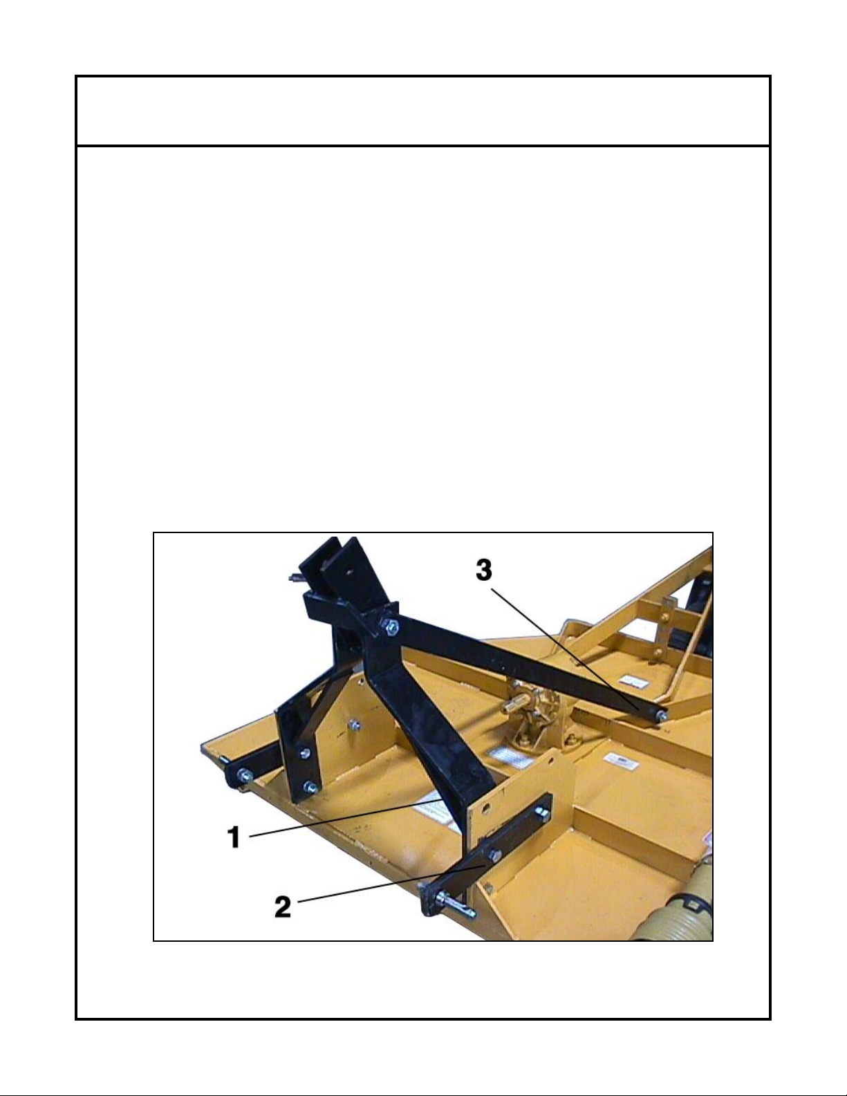
Read and observe all safety decals on the tractor and mower (see page7).
Always operate tractor PTO (power take-off) at recommended
RPM (revolutions per minute).
Stay away from PTO shaft and mower when
engaging PTO.
Disengage tractor PTO and shift into neutral
before attempting to start engine.
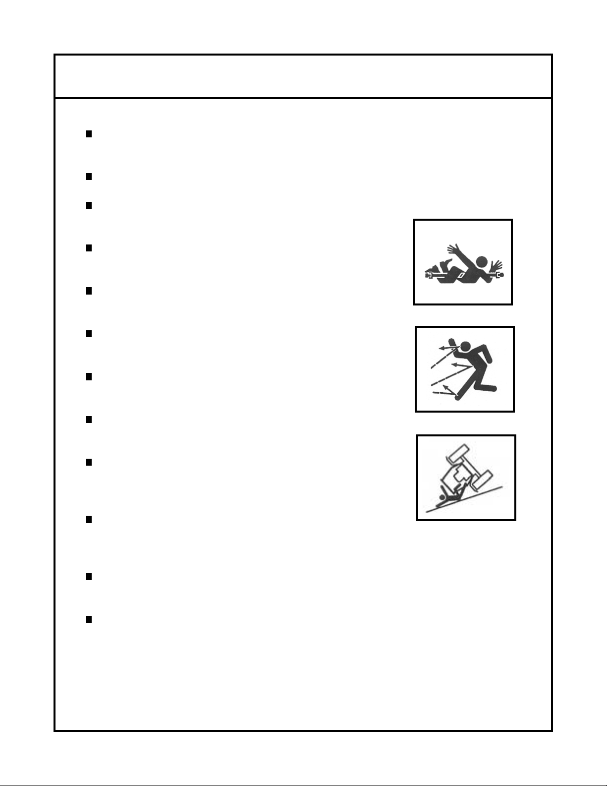
NEVER allow anyone within 25’ of machine
while it is in operation.
DO NOT stop or start suddenly when going uphill
or downhill. Avoid operation on steep slopes.
Be alert for holes in terrain and other hidden hazards.
Always drive slowly over rough ground.
Reduce speed on slopes and in sharp turns to prevent
tipping or loss of control. Be careful when changing
direction on slopes.
Stop mower and tractor immediately upon striking
an obstruction. Turn off engine, inspect mower and
repair any damage before resuming operation.
Disengage power to mower and stop engine before dismounting from tractor,
before making any repairs or adjustments, transporting, or unclogging mower.
Take all possible precautions when leaving tractor unattended. Disengage
PTO, lower mower, shift into neutral, set parking brake, stop engine and
remove key from ignition.
OPERATIONAL SAFETY
Page 5

Continued....
Front tractor weights or front tire ballast should be used to enhance front end
stability on small tractors.
NEVER operate mower in raised position.
Check to make sure PTO is properly connected
and that the driveline is correct to prevent
bottoming out or pulling apart during the full
lift range of the hitch.
This implement is designed for a one-man operation. It is the responsibility
of the tractor operator to see that no one is in the proximity of the implement
when it is started. DO NOT operate the implement when another person is
within 25’ of the implement.
NEVER put hands or feet under mower deck
while tractor engine or mower is running.
OPERATIONAL SAFETY
Page 6

MAINTENANCE SAFETY
Support the mower with safety stands or blocks before working beneath it.
Follow good shop practices:
A. Keep service area clean and dry.
B. Be sure electrical outlets and tools
are properly grounded.
C. Use adequate light for the job at
hand.
Use only tools, jacks and hoists of sufficient capacity for the job.
NEVER work on the mower unless the tractor engine is off and the
driveline is disconnected.
ALWAYS wear heavy canvas or leather gloves when handling mower
blades.
NEVER wear loose or frayed clothing when working on moving parts.
(i.e. gearbox, blade pan, driveline, etc.)
Make sure all guards are in place and properly secured when all
maintenance work is completed.
Page 7

1. Keep all safety decals and signs clean and legible at all times.
2. Replace safety decals and signs that are missing or have become illegible.
(Contact Gearmore at 909.548.4848 for free replacement safety decals.)
MOWER SAFETY DECALS
Page 8

Carefully follow all instructions as stated in this manual. This includes operation,
lubrication, safety and maintenance. This mower was designed and built for years
of reliable service if properly cared for. However, rotary mowers are a high RPM
machine, thus daily attention is required.
Check all bolts for tightness.
Check to make sure all safety guards are in place.
Check to remove any trash build-up.
Check lubrication - see lubrication section.
Check blades to make sure they are securely fastened.
When replacing or grinding blades, both blades must be replaced or re-ground at
the same time to maintain the proper balance in the mower. Gearmore mowers
are equipped with special heat-treated alloy steel blades. Use only Gearmore
blades, substitutes may be dangerous. NEVER try to straighten or weld blades.
DRIVESHAFT - The driveshaft must be lubricated before mower is put into use.
After that, grease every 8 hours of use or when required. It is also necessary, from
time to time, to untelescope the driveshaft to clean and re-grease tubing.
GEARBOX - Check gearbox oil level through square headed screw plug. Add
SAE 90 weight oil when required. Change gearbox oil after every 400 hours of use.
TAILWHEEL - Grease every 8 hours of use or when required.
TAILWHEEL PIVOT TUBE - Grease weekly or when required.
To comply with OSHA AG Guarding Standard #1928.27, the following guards and
shields must be kept in place and in good working condition:
1. Safety chain shielding
2. Driveshaft shields
3. Guards over moving parts
BE CAREFUL AND ALWAYS THINK SAFETY FIRST!
GENERAL MAINTENANCE
9
9
9
9
9
S
SE
ER
RV
VI
IC
CI
IN
NG
G
B
BL
LA
AD
DE
ES
S
L
LU
UB
BR
RI
IC
CA
AT
TI
IO
ON
N
Page 9

TROUBLESHOOTING
P
PR
RO
OB
BL
LE
EM
M
C
CA
AU
US
SE
E
S
SO
OL
LU
UT
TI
IO
ON
N
Excessive vibration Blades are not free to swing. Check bushings and
movements of blades.
Blades are out of balance. Check blades for damage
or replace.
Unusual noise Loose blade bolts or worn bushings. Tighten blade bolts, check
bushings for wear and change
as needed.
Bent blade carrier, blades Replace blade carrier.
striking deck.
Deck bent causing blades to hit. Straighten deck.
Gearbox low of oil. Check seals in gearbox and fill
to proper level.
Poor cutting Not maintaining proper PTO speed. Check PTO with tachometer
and operate at proper RPM.
Improperly adjusted. Adjust according to Operators
Manual.
Forward speed too fast. Coordinate forward speed with
blade speed.
Dull blades. Sharpen blades.
PTO turns and Gears stripped in gearbox. Replace or repair gearbox.
blades do not
Shear bolt sheared. Replace shear bolt.
PTO will not Improper lubrication. Separate and fill female tube
telescope half full of grease.
PTO twisted. Replace twisted portion.
Bent PTO. PTO too long. Size to tractor
according to manual.
Shields damaged. Replace.
PTO twisted Over torqued. Caution operator not to
ground out machine.
Not maintaining correct PTO speed. Maintain proper PTO speed.
Machine streaking Cutting too high, leaving wheel Cut lower and slow forward
tracks. speed down.
Not maintaining proper RPM Maintain proper RPM
speed. speed.
Page 10

MOWER ASSEMBLY L-60-60-HD
REF# QTY. PART NO. DESCRIPTION
1 1 403001 Tire and Rim
2 1 403021 Tailwheel Fork
3 1 191100 Hub Assembly
4 1 403015 A-Frame, Tailwheel
5 1 310612 Adjustment Strap
6 1 184065 Gearbox 60 H.P.
7 2 310074 Lift Arm Braces
8 1 147248 PTO Driveline
9 2 403656 Lift Arm
10 2 500002 Lift Pin Cat. II
11 1 114045 Safety Decal
12 1 501090 Swivel Top Link
13 2 101210 Bolt 3/4” x 2-1/2”
14 1 501280 Axle Bolt
15 1 501100 Bushing
Page 11

MOWER ASSEMBLY L-72 & L-84
L-72 L-84
REF# QTY. QTY. PART NO. DESCRIPTION
1 2 2 403001 Tire and Rim
2 2 2 403021 Tailwheel Fork
3 2 2 191100 Hub Assembly
4 1 403567 Cross Axle Assembly
4 1 403569 Cross Axle Assembly
5 1 184065 Gearbox 60 H.P.
5 1 184080 Gearbox 80 H.P.
6 2 310619 Lift Arm Braces
6 2 310609 Lift Arm Braces
7 1 1 147248 PTO Driveline
8 2 2 403658 Lift Arm
9 1 1 403402 Swivel, Top Link
10 2 2 500002 Lift Pin Cat. II
11 1 1 114045 Safety Decal
12 1 1 195170 Ratchet
13 1 1 501608 Swivel, Top Link
14 4 4 101210 Bolt 3/4” x 2-1/2”
15 2 2 501280 Axle Bolt
16 2 2 501100 Bushing
Page 12

60 HP GEARBOX ASSEMBLY L-60 & L-72
Page 13

60 HP GEARBOX ASSEMBLY L-60 & L-72
REF# QTY. PART NO. DESCRIPTION
1 1 131050 Spacer 1/4”
2 1 185026 Input Gear
3 1 501110 1” Castle Nut
4 1 186015 Input Shaft
5 2 LM603049 Bearing Cone
6 2 LM603014 Bearing Cup
7 1 129020 Housing
8 1 185035 Output Gear
9 2 363 Bearing Cup
10 2 368 Bearing Cone
11 1 186022 Output Shaft
12 1 35X60X10 Oil Seal
13 1 131040 1/8” Pipe Plug
14 1 131035 1/2” Pipe Plug
15 1 129025 Cover, Input
16 2 124133 Gasket
17 2 124134 Gasket
18 1 50X68X9 Oil Seal
19 1 129030 Cover, Output
Page 14

80 HP GEARBOX ASSEMBLY L-84
Page 15

80 HP GEARBOX ASSEMBLY L-84
REF# QTY. PART NO. DESCRIPTION
1 1 131035 1/2” Vented Pipe Plug
2 1 35X60X10 Seal Input
31 1/8” Pipe Plug
4 1 129025 Endcap Input
5 1 124133 Gasket Input
6 1 LM603014 Bearing Race Input
7 1 LM603049 Bearing Input
8 1 Spacer
9 1 185015 Gear Input
10 1 131025 Snap Ring
11 1 186040 Shaft Input
12 1 185035 Gear Output
13 1 362A Bearing Race Output
14 1 368 Bearing Output
15 1 186035 Shaft Output
16 1 362 Bearing Race Output
17 1 124134 Gasket Output
18 1 50X68X9 Seal Output
19 1 129030 Endcap Output
20 1 501110 1” Castle Nut w/Wshr & Cot. Pin
Page 16

BLADE CARRIER ASSEMBLY
REF# QTY. PART NO. DESCRIPTION
1 1 501002 Blade Bolt Assembly, Pair
2 2 190224 Blade L-60-60-HD
2 2 190230 Blade L-72-60-HD & L-84-80-HD
3 1 403041 Blade Carrier L-60-60-HD & L-72-60-HD
3 1 403033 Blade Carrier L-84-80-HD
Page 17

PTO DRIVELINE 147248
REF# QTY. PART NO. DESCRIPTION
1 1 572050351 Yoke 1-3/8" 6 Spline
2 2 41205 Cross Journal Kit #5
3 1 204056860 Yoke, Outer Tube
4 1 341053000 Roll Pin O.T.
5 1 125121200 Tube, Outer Drive
6 1 125091200 Tube, Inner Drive
7 1 341002000 Roll Pin I.T.
8 1 204056861 Yoke, Inner Tube
9 1 403000001 Pin Kit
10 1 240003051 RS Collar Kit
11 1 638141001 Slip Clutch Assembly FF-1
12 1 5F05121FF Complete Shield (not shown)
13 8 351013370 Spring 7mm
14 1 253052001 Flanged Yoke
15 1 258005320 Bushing
16 2 247000054 Lining 140mm
17 1 515200311 Hub 1-3/8" 6 Spline
18 1 408000060 Threaded Bolt Assembly
19 1 248220008 Pressure Plate
20 1 248220007 Cover
21 8 432000006 Bolt & Nut
Page 18
This manual suits for next models
2
Table of contents
Other Gearmore Lawn Mower manuals