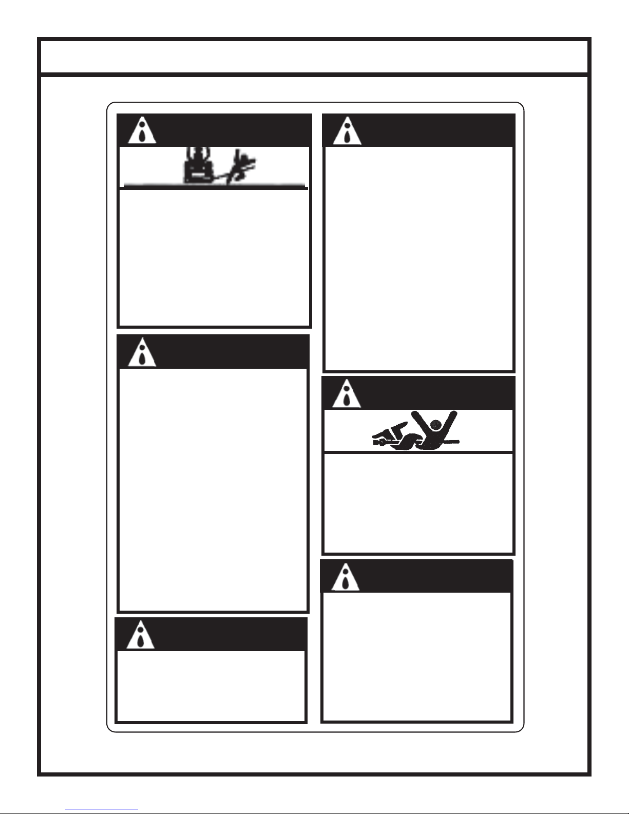
Gearmore RC30-60 Guide

ROTARY
MOWER
Operation, Service &
Parts Manual For
RC30-60, RC30-72,
& RC30-84
February 2006
Form: RC30Mower.pm7

TABLE OF CONTENTS
To The Owner ................................................................................................... 1
Checklists ............................................................................................................ 2
General Safety .................................................................................................... 3
Safety Precautions ............................................................................................. 4
Safety Decals ......................................................................................... 5
Section 1 .............................................................................................................. 6
Description ............................................................................................ 6
Technical Specifications ...................................................................... 7
Section 2 .............................................................................................................. 8
Preparation For Use..........................................................................8-9
Section 3 ............................................................................................................ 10
Operating Instructions ...................................................................... 10
General Safety ..................................................................................... 10
Adjusting for Work ............................................................................ 10
Operation............................................................................................. 11
Section 4 ............................................................................................................ 12
Maintenance Checklist....................................................................... 12
Lubrication .................................................................................... 12-13
Blade Replacement ............................................................................. 13
Slip Clutch Operational Check......................................................... 14
Slip Clutch Adjustment ..................................................................... 14
Torque Specifications ...................................................................................... 15
Section 5 ............................................................................................................ 16
Mower Parts ........................................................................................ 16
Articulated Hitch Assembly.............................................................. 17
Gearbox & Blade Pan Assembly...................................................... 18
Gearbox Assembly ............................................................................. 19
Tailwheel Assembly............................................................................ 20
Chain Guard Assembly ..................................................................... 21
Chain Guard Installation ................................................................... 22
PTO Driveline Assembly .................................................................. 23
Troubleshooting............................................................................................... 24
Limited Warranty ............................................................................................. 25

TO THE OWNER
1
TO THE OWNER:
Please read this manual before using your rotary mower. This manual is provided to give
you the necessary operating and maintenance instructions for keeping your rotary mower in
excellent operating condition. Please read this manual thoroughly. Understand what each
control is for and how to use it. Observe all safety signs on the machine and noted
throughout the manual for safe operation of the implement. Keep this manual handy for
ready reference.
Like all mechanical products, it will require cleaning and upkeep. Lubricate the mower as
specified.
Use only original manufacturer service parts. Substitute parts will void warranty
and may not meet standards required for safe and satisfactory operation.
RETAIL CUSTOMER’S RESPONSIBILITY
It is the retail customer and/or Operator’s responsibility to read the Operator’s
Manual, to operate, lubricate, maintain, and store the product in accordance with all
instructions and safety procedures. Failure of the operator to read the Operator’s
Manual is a misuse of this equipment.
It is the retail customer and/or Operator’s responsibility to inspect the product and
to have any part(s) repaired or replaced when continued operation would cause
damage or excessive wear to other parts or cause safety hazard.
It is the retail customer and/or Operator’s responsibility to deliver the product to the
authorized Dealer, from whom it was purchased, for service or replacement of
defective parts that are covered by warranty. Repairs to be submitted for warranty
consideration must be made within ninety (90) days of failure.
It is the retail customer and/or Operator’s responsibility for any cost incurred by the
Dealer for traveling to or hauling of the product for the purpose of performing a
warranty obligation or inspection.
CUSTOMER INFORMATION
NAME:______________________________________________
PURCHASED FROM: _________________________________
DATE OF PURCHASE:________________________________
MODELNUMBER: ___________________________________
SERIALNUMBER: ___________________________________

DEALER PREPARATION CHECKLIST
2
THIS CHECKLIST TO REMAIN IN OWNER’S MANUAL
ITIS THE RESPONSIBILITY OF THE DEALER TO COMPLETE THE PROCEDURES LISTED
BELOW BEFORE THE DELIVERY OR THE SALE OF THIS IMPLEMENT TO THE CUSTOMER.
Dealer Preparation Check List
1. Implement is completely assembled.
2. Gearbox filled with oil. (See page 12)
3. All fittings lubricated. (See page 12)
4. All shields in place and in good condition.
5. All fasteners torqued to specifications given in Torque Chart. (See page 15)
6. Check PTO driveline. Make sure it is the correct length to operate rotary
mower with intended tractor.
7. Check front of input gearbox shaft and make sure that snap ring is
properly installed. (This is for smooth bore input shaft only.)
8. Check shear bolt for proper grade and installation.
9. All decals in place and readable. (See page 5)
10. Overall condition good (i.e. paint, welds, etc.).
11. Operator's manual has been given to owner and the owner has been instructed
on the safe and proper use of the rotary mower.
12. Purchaser elects to delete deflectors. (front and rear rubber belt, front and
rear chains)
______________________________________________________________________________________________________________________________
WARNING
For Non-Agricultural use OSHA,ASAE, SAE, and ANSI standards require the use of Chain
Guards or other protective guards at all times. Manufacturer strongly recommends the use of
such guards forAgricultural uses as well, to reduce the risk of property damage, serious bodily
injury or even death from objects thrown out by or from contact with the cutting blades.
Dealer's Signature:____________________________________
Purchaser's Signature:__________________________________

GENERAL SAFETY
3
WARNING
NEVER STAND BETWEEN TRACTOR AND MOWER WHILE TRACTOR IS BEING BACKED TO HITCH
WARNING
ADDITIONAL TRACTOR FRONT BALLAST MAY BE NEEDED FOR STABLE OPERATION AND
TRANSPORT OF THE 3-POINT HITCH MOUNTED MOWER. SEE TRACTOR OPERATOR'SMANUAL FOR
RECOMMENDED WEIGHTS.
WARNING
DONOT USE PTO SHAFT ADAPTERS TO CHANGE SIZE OF TRACTOR PTO SHAFT. THE CORRECT
DRIVELINE MUST BE USED TO MATCH TRACTOR PTO SHAFT.
WARNING
THE MOWER CAN FALL FROM HYDRAULIC SYSTEM FAILURE. TOAVOID SERIOUS INJURY OR
DEATH, SECURELY SUPPORT CUTTER BEFORE WORKING UNDERNEATH.
WARNING
AVOID PLACING HANDS, FEET OR ANY OTHER BODY PARTS BENEATH THE MOWER WHILE
MAKING HEIGHT ADJUSTMENTS.
DANGER
STAY CLEAR OF ROTATING DRIVELINE. DONOT OPERATE WITHOUT DRIVELINE SHIELDS IN
PLACE AND IN GOOD CONDITION. FAILURE TO HEED THESE WARNINGS MAY RESULT IN
PERSONAL INJURY OR DEATH.
DANGER
ROTATING MOWER BLADES - STAND CLEAR UNTIL ALL MOTION HAS STOPPED. TOAVOID AN
ACCIDENTAL FALL FROM TRACTOR AND POSSIBLE INJURY BY MOWER, IT IS RECOMMENDED THAT
TRACTOR BE EQUIPPED WITH ROLLOVER PROTECTIVE SYSTEM (ROPS) AND ASEAT BELT BE
USED BY THE OPERATOR FOR ALL MOWING OPERATIONS.
WARNING
ALL ROTARY MOWERS CAN DISCHARGE OBJECTS AT HIGH SPEEDS WHICH COULD RESULT IN
SERIOUS INJURY TO BYSTANDERS OR PASSERSBY. THEREFORE, THIS MOWER IS NOT TO BE
OPERATED ALONG HIGHWAYS OR IN ANY AREA WHERE PEOPLE MAY BE PRESENT UNLESS ALL
SIDES OF THE UNIT ARE ENCLOSED BY PERMANENT BANDS THAT ARE IN GOOD REPAIR.
DANGER
DONOT GET UNDER MOWER UNLESS IT IS SECURELY BLOCKED IN POSITION.ACCIDENTAL FALL
COULD CAUSE SERIOUS INJURY OR DEATH.
WARNING
FAILURE TO INSTALL RETAINING CLIP ON INPUT SHAFT WILL ALLOW DRIVELINE TO SWING
FREELY IF BOLT IS SHEARED CAUSING POSSIBLE INJURY OR DEATH.
WARNING
ROTARY MOWERS MUST BE EQUIPPED WITH FRONT AND REAR GUARDS WHEN OPERATING IN THE
VICINITY OF HIGHWAYS OR IN ANY AREA WHERE PEOPLE MAY BE PRESENT.

SAFETY PRECAUTIONS
4
Most accidents occur because of neglect or carelessness.Avoid needless accidents by following all of the
safety precautions listed below.
Machinery should be operated only by those who are responsible and are authorized to do so.
Stop the engine, lower implement, lock the brakes, and remove the ignition key before dismounting from
the tractor.
Never stand between tractor and implement while tractor is being backed to hitch.
Loose fitting clothing should not be worn to avoid catching on various parts.
Detach implement in area where children normally do not play.
When performing adjustments or maintenance on an implement, first lower it to the ground or block it
securely at a workable height.
Only a qualified operator should be permitted on tractor when in operation; no riders allowed.
Make certain everyone is in the clear before starting tractor or raising or lowering implement.
Operate the tractor and implement only while in driver's seat.
Reduce speed when transporting mounted implements to avoid bouncing and momentary loss of steering
control.A heavy load can cause instability of the tractor. Use extreme care during road travel. Slow
down on turns and watch out for bumps. Tractor may need front counter-weights to counter-balance the
weight of the implement.
Reduce speed on hillsides or curves so there is no danger of tipping.
Avoid driving too close to the edge of ditches or creeks.
Do not transport implement on public roads without reflectors and slow moving vehicle emblem in
daylight and with approved warning lights at night and other periods of poor visibility.
Due to the width of some implements, use extra caution on highways, farm roads, and when approaching
gates.
Always be sure the implement is in the proper position for transport.
Keep alert and watch the front as well as the rear when working with the implement.
ALWAYS KEEPCHILDRENAWAY FROM DANGER WHEN OPERATINGTRACTORAND
IMPLEMENT.
EQUIPTRACTORS WITH ROLLOVER PROTECTION (ROPS)AND KEEPALL
MACHINERY GUARDS IN PLACE.
PLEASE WORK, DRIVE, PLAY,AND LIVE EACH DAY WITH CAREAND CONCERN FOR
YOUR SAFETYAND THAT OFYOUR FAMILYAND FELLOW CITIZENS.

SAFETY DECALS
5
ROTARY MOWERS MAY DISCHARGE OBJECTS
AT HIGH SPEEDS, WHICH COULD RESULT IN
SERIOUS INJURY TO BY-STANDERS OR
PASSERS-BY.
DO NOT OPERATE MOWER IN
VICINITY OF OTHER PERSONS.
KEEP ENCLOSED SIDES, PERMANENT
BANDS, BELTING, HIGHWAY CHAINS
OR OTHER FACTORY APPROVED
DISCHARGE SHIELDS IN PLACE AND IN
GOOD REPAIR.
WARNING WARNING
IMPLEMENT CAN FALL FROM HYDRAULIC
SYSTEM FAILURE. TOAVOID SERIOUS
INJURY OR DEATH:
BLOCK UP OR SECURELY SUPPORT IMPLEMENT
BEFORE WORKING UNDERNEATH.
PURGE ALL AIR FROM HYDRAULIC SYSTEM
BEFORE ATTEMPTING TO RAISE OR LOWER
THIS IMPLEMENT.
STAND CLEAR IF LOWERING OR RAISING
IMPLEMENT.
DONOT USE HAND OR SKIN TO CHECK FOR
HYDRAULIC LEAKS. USE CARDBOARD OR
WOOD.
HIGH PRESSURE OIL LEAKS CAN PENETRATE
SKIN CAUSING SERIOUS INJURY AND GAN-
GRENE. CONSULT APHYSICIAN IMMEDIATELY.
LOWER THE IMPLEMENT AND RELEASE
HYDRAULIC PRESSURE BEFORE LOOSENING
FITTINGS.
REFER TO OWNER'SMANUAL FOR DETAILS.
DANGER
DANGER
CAUTION
WARNING
TOAVOID SERIOUS INJURY OR DEATH:
READ OPERATOR'SMANUAL BEFORE
OPERATING & FOLLOW ALL PRECAUTIONS.
(CONTACT DEALER FOR MANUALS)
KEEP SHIELDS AND GUARDS IN PLACE. KEEP
CLEAR OF DRIVES AND BELTS.
LOWER IMPLEMENT, STOP ENGINE AND
REMOVE KEY BEFORE DISMOUNTING.
SECURELY SUPPORT MOWER & REMOVE KEY
BEFORE WORKING UNDERNEATH.
NORIDERS. DONOT OPERATE MOWER IN
VICINITY OF OTHER PERSONS.
KNOW HOW TO STOP TRACTOR AND
EQUIPMENT QUICKLY IN AN EMERGENCY.
CLEAR MOWING AREA OF DEBRIS.
ALLOW NO CHILDREN OR UNQUALIFIED
PERSONS TO OPERATE EQUIPMENT.
BECAREFUL ON UNEVEN TERRAIN.
DECREASE SPEED WHEN TURNING.
DONOT OPERATE MOWER IN TRANSPORT
POSITION.
THIS IMPLEMENT IS DESIGNED TO OPERATE
AT 540 RPM MAXIMUM TRACTOR PTO
SPEED.
ALL DRIVELINE SHIELDS MUST BE KEPT IN
PLACE.
ROTATINGDRIVELINE
CONTACT CAN CAUSE DEATH
KEEPAWAY
DO NOT OPERATE WITHOUT -
ALL DRIVELINE, TRACTOR AND EQUIPMENT
SHIELDS IN PLACE
DRIVELINES SECURELY ATTACHED AT BOTH ENDS
DRIVELINE SHIELDS THAT TURN FREELY ON
DRIVELINE.
KEEPAWAY - ROTATING BLADES
SERIOUS INJURY OR DEATH CAN RESULT FROM
THROWN OBJECTS OR BLADE CONTACT
DO NOT STAND ON OR NEAR MACHINE
WHEN IN OPERATION
DO NOT OPERATE WITH DEFLECTORS OR
GUARDS REMOVED.
ROPS (ROLLOVER PROTECTIVE SYSTEM)
AND SEAT BELT EQUIPPED TRACTOR IS
RECOMMENDED FOR OPERATOR USE IN ALL
MOWING OPERATIONS.

SECTION 1 - DESCRIPTION
6
Your standard duty RC30 Rotary Mower has been carefully designed for cutting grass and small
brush. This manual is provided to give you the necessary operation and maintenance instructions
for keeping your rotary mower in excellent operating condition. Please read this manual
thoroughly. Understand the purpose of the controls and how to use them. Observe all safety
precautions on the machine and noted throughout this manual. If any assistance or additional
information is needed, contact your authorized dealer. Each mower has free-swinging blades which
reduce the shock on impact when a stationary object is hit. A slip clutch through the input shaft
protects the gearbox and driveline from damage on all models.
Figure 1-1 Major Components
A-Frame
Driveline
Deck
Gearbox
Tailwheel

TECHNICAL SPECIFICATIONS
7
MODEL NO: RC30-60 RC30-72 RC30-84
Cutting Width: 60" 72" 84"
Cutting Height: 1 1/2" - 9" 1 1/2" - 9" 1 1/2" - 9"
Cutting Capacity: Up to 2" Diameter Up to 2" Diameter Up to 2" Diameter
Hitch: Cat. I (Clevis Style) Cat. I (Clevis Style) Cat. I (Clevis Style)
Machine Weight: 905 lbs. 1040 lbs. 1240 lbs.
Gearbox Rating: 85 HP 85 HP 85 HP
Blade Size: 1/2" x 4" 1/2" x 4" 1/2" x 4"
Blade Tip Speed: 12,645 fpm 14,955 fpm 17,448 fpm
Deck Thickness: 10 Gauge 10 Gauge 10 Gauge
Side Skirt Thickness: 1/4"1/4"1/4"
Side Skirt Height: 7 3/4"7 3/4"7 3/4"
Type Tailwheel: Laminated Laminated Laminated
Blade Carrier: Round Round Round
Gearbox Protection: Slip Clutch Slip Clutch Slip Clutch
Recommended Tractor HP: 42 to 85 45 to 85 50 to 85
DUALTAILWHEELOPTIONAL

SECTION 2 - Preparation For Use
8
WARNING
NEVER STAND BETWEEN TRACTOR AND ROTARY MOWER WHILE TRACTOR IS BEING
BACKED TO HITCH
WARNING
ADDITIONAL TRACTOR FRONT BALLAST MAY BE NEEDED FOR STABLE OPERATION AND
TRANSPORT OF THE 3-POINT HITCH MOUNTED MOWER. SEE TRACTOR OPERATOR'SMANUAL FOR
RECOMMENDED WEIGHTS.
WARNING
DONOT USE PTO SHAFT ADAPTERS TO CHANGE SIZE OF TRACTOR PTO SHAFT. THE CORRECT
DRIVELINE MUST BE USED TO MATCH TRACTOR PTO SHAFT.
A. Insure that all bolts and hitch pins on 3-point hitch are tightened. Hitches need no further
adjustment.
B. Attach rotary mower to tractor 3-point hitch per tractor operator's manual. Do not attach
driveline at this time. (figure 2-1)
C. Raise 3-point hitch until front of mower is approximately 1 - 2 inches (25-51 mm) lower
than rear for standard cut or until front of mower is 1 inch (35 mm) higher than rear for
extra shredding. Shut down tractor. Securely block mower in position. For further
explanation of rotary mower adjustment, see paragraph 3-2.
NOTE:
Due to the many variations in tractor/implement hitch points and corresponding differences in
distances between tractor PTO shafts and implement input shafts, drivelines may need to be
shortened as described in the following steps:
D. Raise and lower rotary mower to determine position with shortest distance between the
tractor PTO shaft and gearbox input shaft. Shut down tractor leaving cutter in position of
shortest distance. Securely block rotary mower in position.
E. Pull driveline apart. Attach outer (female) section to tractor PTO shaft. Pull on driveline
section to be sure that yoke locks into place.
F. Hold driveline sections parallel to each other to determine if too long. Each section should
end approximately 3 inches (76 mm) short of reaching universal joint shield on opposite
section. If too long, measure 3 inches (76 mm) back from universal joint shield and mark on
opposite section. (figure 2-2). Do this for both sections.
G. Raise and lower rotary mower to determine position with greatest distance between PTO
shaft and gearbox input shaft. Shut down tractor leaving rotary mower in position of
greatest distance. Securely block rotary mower in position.

9
PREPARATION FOR USE
Figure 2-1 (3-Point Hitch Points)
Top Link Hitch Point
Lift Arms
Hitch Pins
Figure 2-2
H. Hold driveline sections parallel to each
other and check for a minimum of 6"
(15cm) overlap. (Figure 2-3). If driveline
has been marked for cutting, overlap will
be the distance between two marks. If
driveline has less than minimum overlap, do
not use. Contact authorized dealer.
Figure 2-3
NOTE:
If driveline is the correct length, omit the following
steps "I" through "L" and proceed to step "M".
I. Clamp driveline in a well padded vice to
prevent damage to the shield. Cut off shield
where marked. (Figure 2-4)
Figure 2-4
J. Using cut off section of shield as a guide, cut
shaft the same amount. (Figure 2-5)
K. Repeat steps "I" and "J" to other driveline
section.
Figure 2-5
L. Deburr ends of driveline sections and clean
away all chips and fillings. (Figure 2-6)
M. Apply multi-purpose grease to inside of
outer (female) driveline section. Assemble
driveline and install on tractor and rotary
mower. Pull on each driveline section to be
sure yokes lock into place. Make certain
driveline shielding is in place and in good
condition.
Figure 2-6
N. Adjust lower lift arm(s) to level rotary
mower right to lift. Refer to tractor operator's
manual for instructions.
NOTE:
After attaching driveline to tractor, attach driveline
shield chains from both ends of driveline shielding to
stationary locations.
Minimum
Overlap

SECTION 3 - Operating Instructions
10
3-1 GENERAL SAFETY
Only qualified people should operate this machine. Operator should wear hard hat, safety glasses, and
safety shoes. It is recommended that tractor be equipped with Rollover Protective Systems (ROPS) and
a seat belt be used. Before beginning operation, clear work area of objects that may be picked up and
thrown. Check for ditches, stumps, holes, or other obstacles that could upset tractor or damage rotary
mower.Always turn off tractor engine, set parking brake, and allow rotary mower blades to come to a
complete stop before dismounting tractor.
3-2 ADJUSTING FOR WORK
The rotary mower should be operated at the highest position which will give optimal cutting results.
This will help prevent the blades from striking the ground, reducing blade wear and undue strain on the
machine. For best results under heavier cutting conditions, always tilt the rotary mower approximately
2 inches (51mm) lower in the front. This tilt decreases horsepower requirements and increases potential
ground speed. When fine shredding is desired, adjust rotary mower deck level or slightly lower in the
rear. This will keep the foliage under rotary mower until thoroughly shredded. More power is required
for shredding.
WARNING
THE MOWER CAN FALL FROM HYDRAULIC SYSTEM FAILURE. TOAVOID SERIOUS INJURY OR
DEATH, SECURELY SUPPORT ROTARY MOWER BEFORE WORKING UNDERNEATH.
WARNING
AVOID PLACING HANDS, FEET OR ANY OTHER BODY PARTS BENEATH THE ROTARY MOWER
WHILE MAKING HEIGHT ADJUSTMENTS.
Figure 3-1 Tailwheel Height Adjustment Each rotary mower can be adjusted to several
cutting heights. The RC30 can be adjusted to
approximately 1-1/2" to 9" of cutting height. To
adjust, raise rotary mower and block securely in
position. Remove bolt from adjusting strap
shown in Figure 3-1. Adjust tailwheel frame up
or down and secure in desired position.
Adjustment Bolt

11
OPERATING INSTRUCTIONS
Tractor 3-point hitch top link must be adjusted so
that rotary mower top link has a small amount of
slack when in the work position. (See Figure 3-2)
3-3 OPERATION
A. Perform BEFORE EACH USE
maintenance listed in paragraph 4-1.
B. Start tractor per tractor operator's manual.
C. Raise/lower 3-point hitch to place mower
in working position.
D. Look to be sure no one is near mower.
WITH TRACTORAT IDLE SPEED,
SLOWLY ENGAGE PTO DRIVE.
DANGER
STAY CLEAR OF ROTATING DRIVELINE. DONOT OPERATE WITHOUT DRIVELINE SHIELDS IN
PLACE AND IN GOOD CONDITION. FAILURE TO HEED THESE WARNINGS MAY RESULT IN
PERSONAL INJURY OR DEATH.
WARNING
ROTATING MOWER BLADES STAND CLEAR UNTIL ALL MOTION HAS STOPPED. TOAVOID AN
ACCIDENTAL FALL FROM TRACTOR AND POSSIBLE INJURY BY MOWER, IT IS RECOMMENDED THAT
TRACTOR BE EQUIPPED WITH ROLLOVER PROTECTIVE SYSTEM (ROPS) AND ASEAT BELT BE
USED BY THE OPERATOR FOR ALL MOWING OPERATIONS.
WARNING
ALL ROTARY MOWERS CAN DISCHARGE OBJECTS AT HIGH SPEEDS WHICH COULD RESULT IN
SERIOUS INJURY TO BYSTANDERS OR PASSERS-BY. THEREFORE, THIS ROTARY MOWER IS NOT TO
BE OPERATED ALONG HIGHWAYS OR IN ANY AREA WHERE PEOPLE MAY BE PRESENT UNLESS ALL
SIDES OF THE UNIT ARE ENCLOSED BY PERMANENT BANDS THAT ARE IN GOOD REPAIR.
E. Set tractor throttle for appropriate PTO speed (540 RPM).
F. Place tractor in gear and proceed forward.Advance throttle to 540 PTO rpm. Tractor
forward speed should be controlled by gear selection, not engine speed. For maximum
cutting efficiency, forward speed should allow rotary mower to maintain a constant,
maximum blade speed. If rotary mower stalls or tractor engine bogs, disengage PTO.
Before re-engaging PTO, position rotary mower in a cut area and reduce tractor throttle to
idle. If rotary mower continuously stalls, select lower gear and/or increase cutting height.
Figure 3-2 Top Link Position

SECTION 4 - Maintenance
12
4-1 MAINTENANCE CHECKLIST
Perform scheduled maintenance as outlined below. Lower machine to ground, turn off tractor and set
parking brake before doing maintenance inspections or work.All bolts should be torqued as recom-
mended in the Torque Specifications unless otherwise indicated.
BEFORE EACH USE:
1. Check tractor tire air pressure. Refer to tractor operator's manual.
2. Check blades and spindles to be sure that no foreign objects such as wire or steel strapping
bands are wrapped around them.
3. Check blade bolts for tightness. (Tighten to 325 ft./lbs. (814 NM) on model RC30)
4. Inspect blades for wear. Replace if necessary per paragraph 4-3.Always replace both blades on
blade holder with two blades equal in weight.
5. Make certain driveline shields are in place and in good repair.
6. Inspect wheel for wear, damage, or foreign objects. (Repair or replace if necessary)
7. Perform BEFORE EACH USE lubrication per paragraph 4-2.
8. During operation, listen for abnormal sounds which might indicate loose parts, damaged
bearings, or other damage.
AFTER EACH USE:
1. Clean all debris from rotary mower, especially under side of deck. When cleaning underside of
deck, securely block machine into position.
4-2 LUBRICATE AS FOLLOWS: (See Figure 4-1 & 4-2)
NOTE:
The multi-purpose grease referenced in this section is a NLGI Grade 2 type grease.
BEFORE EACH USE:
1. Driveline Universal Joints -Apply multi-purpose grease with a grease gun.
2. Driveline Guard - (See Figure 4-2)Apply 2-3 shots of multi-purpose grease with grease gun to
plastic fitting.
3. Driveline - Disconnect PTO driveline, pull two sections apart and apply thin coat of multi-
purpose grease to inside of outer female section. Re-assemble sections and install. Pull each
section to be sure driveline and shields are securely connected. Make certain PTO shielding is
in good condition.
4. Wheel Pivot Tube -Apply multi-purpose grease with grease gun.
5. Tailwheel - Apply multi-purpose grease with grease gun.
6. Gearbox - Check oil level by removing oil level check plug on side of gearbox. Add EP80W-90
gear oil if necessary to bring oil level to check plug hole.
AT THE END OF YOUR MOWING SEASON:
1. Drain and change the oil in your gearbox.
2. Check (and replace where necessary) blades, bolts, and nuts on the machine.
3. Clean machine and touch up any rust spots that may have appeared.
4. Replace any safety signs if damaged.
5. Store rotary mower in a clean dry location.

13
MAINTENANCE
Figure 4-1
4-3 BLADE REPLACEMENT
It is not necessary to remove the complete blade holder
assembly to replace the blades. Blade bolts are accessible
through a hole in the top of the mower deck.Always re-
place both blades on a blade holder using two blades having
the same weight. Use only OEM replacement blades. (See
Figure 4-3)
A. Raise rotary mower and securely block in position
B. Remove nuts from blade bolts through the access
hole in the mower deck (Figure 4-3). The RC30
requires a 1 5/16" socket.
C. Inspect blade bolt shoulder for wear. Replace if
necessary.
D. Assemble new blades to blade holder using
blade bolts, nuts, and lockwashers. Tighten nuts
to 325 ft./lbs.
E. Check to be sure blades swing 360ofreely. If blades
will not swing freely, remove, locate problem, and
repair. Operating rotary mower when blades will not
swing freely will cause excessive vibration, damaging
implement.
Figure 4-2
Before Each Use
To remove yoke shield: Turn slotted head
90owith screwdriver, remove turn screw
and slide cover back.
Figure 4-3 Blade Removal

MAINTENANCE
14
4-5 SLIP CLUTCH OPERATIONAL CHECK
After the implement has been stored for 30 days or more, perform the following operational check:
A. Loosen eight nuts retaining clutch springs 1/3 turn or until spring can be turned with fingers.
B. With tractor at idle speed, engage tractor PTO drive 2-3 seconds. Clutch should slip without
turning blades. If clutch does not slip, contact your authorized dealer.
C. Retighten nuts to original position. Initial spring lengths are shown in Figure 4-5.
IMPORTANT:
FAILURE TO RETIGHTEN NUTS TO ORIGINALPOSITION MAYCAUSE DAMAGE TO
IMPLEMENTAND/OR TRACTOR DUE TO IMPROPER SLIP CLUTCH TORQUE SETTING
4-6 SLIP CLUTCH ADJUSTMENT
The slip clutch is factory preset to the correct torque for protecting
implement and tractor. Periodic adjustment is recommended; refer
to section 4-5. Should adjustments be needed, first check to be sure
all spring lengths are the same. Initial spring lengths are shown in
Figure 4-5. If necessary, adjust nut on any spring that is unequal.
Adjust all eight spring retaining nuts 1/3 of a turn (2 flats on a nut)
and check clutch slippage. If further adjustment is necessary, do so
in 1/3 turn increments. Adjust only to provide sufficient torque to
prevent slippage under normal conditions. Occasional slippage is
normal for driveline protection. If satisfactory results cannot be
obtained, consult your authorized dealer.
Figure 4-5 Spring Lengths
PTO Drive Slip Clutch

15
TORQUE SPECIFICATIONS

SECTION 5 - Parts
16
REF# QTY. PART NO. DESCRIPTION
1 1 N/A DeckAssembly
2 2 100107 Brand Label
3 1 300101 Warning / Danger Decal
4 2 300146 Top Link Mount
5 1 300111 Hitch Pivot Link
6 2 300147 Lift Strap - 60"
6 2 300148 Lift Strap - 72"
6 2 300149 Lift Strap - 84"
7 1 300141 Gearbox - 85 HP
8 1 300124 Slip Clutch Shield
9 1 300145 TailwheelAdjustment Bracket
10 1 100138 TailwheelAdjustment Pin
11 1 300142 Tailwheel Beam 60"
11 1 300143 Tailwheel Beam 72"
11 1 300144 Tailwheel Beam 84"
12 1 300109 Tailwheel Fork
13 1 300110 TailwheelAssembly
14 2 100140 Dust Cover (Black Plug)

17
ARTICULATED HITCH ASSEMBLY
REF# QTY. PART NO. DESCRIPTION
1 1 N/A Hitch Mount Lug
2 2 300146 Top Link Mount
3 1 300112 Lift Link Bushing
4 1 300111 Hitch Pivot Link
5 2 300147 Lift Strap 60"
5 2 300148 Lift Strap 72"
5 2 300149 Lift Strap 84"
6 1 100102 Hitch Bolt 3/4" x 5", Grade 5
7 2 100111 Flat Washer 3/4"
8 1 100112 Lock Nut 3/4"
9 2 100139 Pull Pin 7/8x 4 1/4"
10 1 100102 Link Pivot Bolt 3/4" x 5", Grade 5
11 2 100111 Flat Washer 3/4"
12 1 100112 Lock Nut 3/4"
13 1 100110 Hitch Bolt 3/4" x 2 1/2", Grade 5
14 1 100111 Flat Washer 3/4"
15 1 100112 Lock Nut 3/4"

GEARBOX & BLADE PAN ASSEMBLY
18
REF# QTY. PART NO. DESCRIPTION
1 1 300150 Blade Pan 60"
1 1 300151 Blade Pan 72" & 84"
2 1 300152 Blade Set (2 blades) 60" & 72"
2 1 300153 Blade Set (2 blades) 84"
3 2 300117 Blade Washer
4 1 300118 Blade Bolt Set
5 1 300154 RC30 Series 5 PTO Shaft w/slip clutch
6 1 300141 85 HP Gearbox
7 1 300203 Blade Hub Nut
8 1 100113 Cotter Pin - Gearbox
9 1 300124 Slip Clutch Shield
IMPORTANT
When sharpening blades, grind each blade the same
amount to maintain balance. Replace blades in pairs.
Unbalanced blades will cause excessive vibration
which can damage gearbox bearings. Vibration may
also cause structural cracks to mower deck.
Sharpen both blades at the same time to maintain
balance. Follow original sharpening pattern. Do not
sharper blade to a razor edge, but leave at least a 1/16"
blunt edge. Do not sharpen back side of blade.
This manual suits for next models
2
Table of contents
Other Gearmore Lawn Mower manuals
Popular Lawn Mower manuals by other brands

Montgomery Ward
Montgomery Ward ZYJ-244B Owner's guide and parts list

Husqvarna
Husqvarna GTH260TWIN instruction manual

Poulan Pro
Poulan Pro PRK17H42STA owner's manual

Worx
Worx LANDROID WG792E Original instructions

MTD
MTD 124-280A Owner's operating service instruction manual

Great Dane
Great Dane GDSZ48-14KA Technical manual