1
Congratulations on your purchase of the GefenTV 2.1 Audio Amplier w/ Volume
Stabilizer. Your complete satisfaction is very important to us.
GefenTV
GefenTV is a unique product line catering to the growing needs for innovative
home theater solutions. We specialize in total integration for your home theater,
while also focusing on going above and beyond customer expectations to ensure
you get the most from your hardware. We invite you to explore our distinct
product line and hope you nd your solutions.
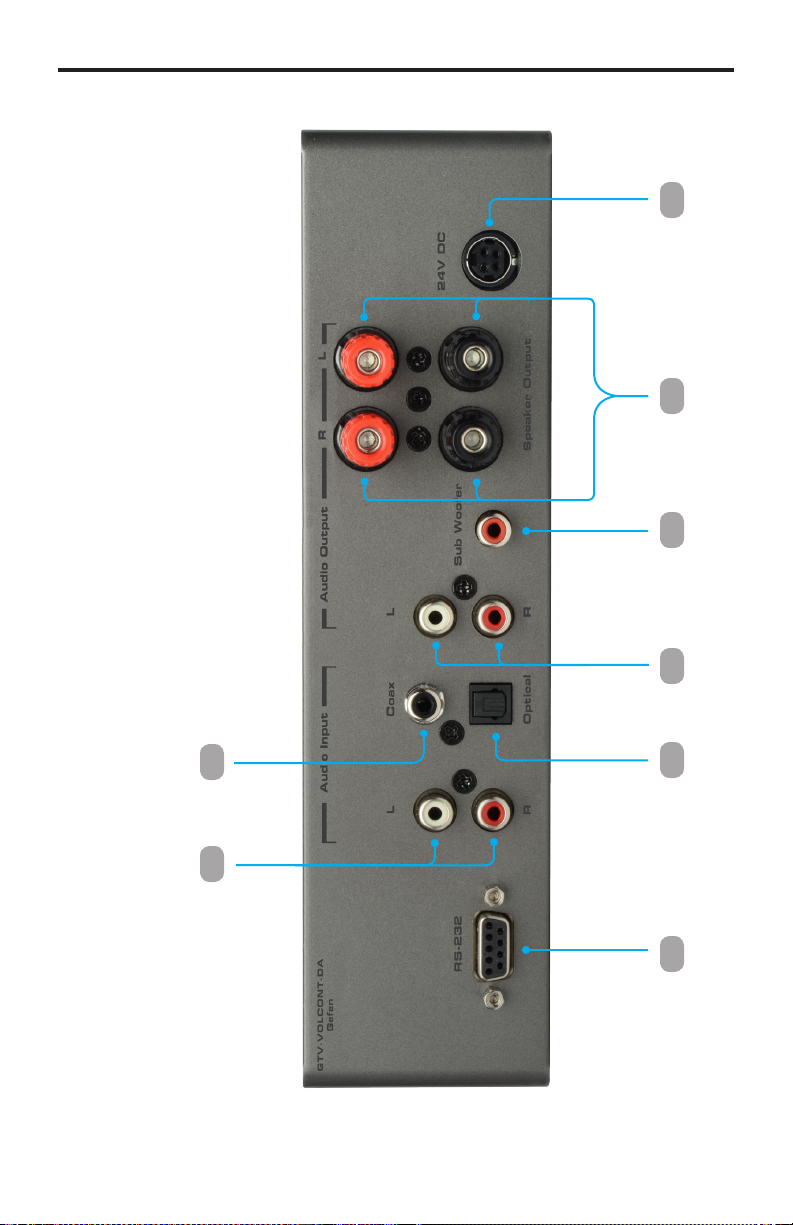
The GefenTV 2.1 Audio Amplier w/ Volume Stabilizer
The GefenTV 2.1 Audio Amplier w/Volume Stabilizer is well suited for use in
small home entertainment systems or as an add-on audio processor to any
computer audio output. It offers three audio inputs (TOSLINK®, S/PDIF, Analog
L/R) for multiple audio sources. The product also incorporates a Dolby® Digital
decoder decoder to downmix 5.1 to 2.1 channels of audio. Dolby® Volume
Technology automatically outputs consistent audio levels regardless of the
program type (commercials, movies, or TV shows). The GefenTV 2.1 Audio
Amplier w/ Volume Stabilizer provides amplication of up to 25 Watts per
channel (Left and Right) fed through the unit’s speaker output binding posts
plus line-level output for a powered subwoofer. This product switches to standby
mode when not in use. An RS-232 port is provided for home automation
control. For easy access and control, use the front panel control buttons with an
illuminated LCD display, or the included IR remote control from several feet away.
How It Works
Connect the audio input source(s) to the GefenTV 2.1 Audio Amplier w/ Vol-
ume Stabilizer. Connect the speakers using speaker wires (not included) to the
Speaker Output binding posts. Connect the included RS-232 cable from the
RS-232 port to your home automation control device (optional). Plug in the in-
cluded power supply to the 24V DC power jack on the rear panel of the unit and
to a power outlet. Use the front panel buttons or the included IR remote to control
the front panel display menu functions, Mute, Input Select, Bypass, and Standby
mode.
INTRODUCTION