Gekasmetal AMANDA User manual

AIR HEATER PELLET STOVE BY GEKASMETAL
Page 1
AMANDA 9KW
Manual

AIR HEATER PELLET STOVE BY GEKASMETAL
Page 2
Please read the instructions carefully before installation, use and maintenance
This manual of use constitutes integral part of the product.
Dear client,
Thank you for placing your confidence in our company and congratulations for your choice!
You have purchased one of the many products of Gekas Metal company, intended for the heating of private or public spaces with the use of solid fuels. You are able to
choose, from our wide variety, a model that fits your needs and demands.
You are now the owner of a pellet hot-air stove constructed by the Greek company GEKAS METAL .
The pellet stove is an ideal heating solution. It uses advanced technology and it has been constructed according the highest standards, with modern design that allows you to
enjoy your heat with absolute safety.
This manual tells you how to use your heater properly. Please read the entire manual carefully before using the heater.
CONTENTS
1. WARNINGS AND GUARANTEE TERMS.......................................................................................................3
SAFETY INSTRUCTIONS............................................................................................................................................3
REFERENCE STANDARDS.........................................................................................................................................5
GUARANTEE TERMS...................................................................................................................................................5
RESTRICTIONS......................................................................................................................................................5
EXCEPTIONS..........................................................................................................................................................5
2. INSTALLATION INSTRUCTIONS.................................................................................................................................6
GENERAL INSTRUCTIONS...............................................................................................................................................6
PELLET..............................................................................................................................................................6
INSTALLATION....................................................................................................................................................6
INSTALLATION AREA REQUIREMENTS...........................................................................................................7
INSTALLATION AREA VENTILATION.........................................................................7
INSTALLATION OF FUME EXTRACTION SYSTEM................................................................................................7
INSTALLATION OF AIR INDUCTION SYSTEM...........................................................................................................7
INSTALLATION OF SWIVEL OR FUME RECEPTOR...................................................................................8
CONNECTION TO ELECTRIC NETWORK.....................................................................................................................8
TECHNICAL DOCUMENTATION OF INSTALLATION.....................................................................................................8

AIR HEATER PELLET STOVE BY GEKASMETAL
Page 3
3. FUMES EXTRACTION SYSTEMS.............................................................................................................8
FLUE....................................................................................................................................................9
ADDITIONAL REQUIREMENTS FOR APPLIANCES EQUIPPED WITH ELECTRIC FAN FOR FUME DISCHARGE.................................................10
EXAMPLES OF PROPER CONNECTION...............................................................................................................10
FLUE TERMINALS..........................................................................................................................11
COMBUSTION PRODUCTS MOUTH HEIGHT............................................................................................11
PRODUCT REQUIREMENTS FOR THE FUME EXTRACTION SYSTEM...............................................12
4. CLEANING AND MAINTENANCE..............................................................................................................12
5. TECHNICAL CHARACTERISTICS.................................................................................................................14
6. OPERATION.........................................................................................................................................15
7. ERRORS..............................................................................................................................................20
1.WARNINGS AND GUARANTEE TERMS
SAFETY INSTRUCTIONS
• The installation, electrical connection , functional verification and maintenance should be executed by professional and authorized personnel only.
• Install the appliance according to all local and national codes and regulations.
• This appliance is not intended for use by persons (including children) with reduced physical, sensory or mental capabilities, or lack of experience and knowledge, unless
they have been given supervision or instruction concerning use of the appliance by a person responsible for their safety.
• Make use of the expectable burning fuels only. The product should not be used as an incinerator. The use of liquid fuels is strictly forbidden.
• The instructions provided in this manual should always be adhered, to ensure the fact that the product and any electric appliance connected to it are used properly and
accidents are prevented.
• The user, or operator of the appliance, should read and fully comprehend the content of this manual before attempting any use of it . Mistakes or incorrect adjustments
may cause dangerous conditions or/and poor function of the appliance.
• Children should be supervised in order to assure they are not playing with the appliance.
• Do not touch the generator with bare feet or with wet body parts.
•Modification or adjustment of the appliance without authorization or instructions by the constructor is forbidden.
• Do not pull, disconnect or twist the wires of the heater even if it is not connected to electric power.
• The use of an electric wire is suggested in order to avoid any contact with the hot parts of the appliance.
• The input plug should be accessible after the installation of the appliance.
• Avoid closing or reducing the dimensions of the ventilation openings in the area where the appliance is installed. The openings are necessary for proper combustion.
• Do not let parts of the package close to children or persons with special needs without help.
• During regular functioning of the appliance the door of the stove should always remain closed.
• Check for obstacles before activating the appliance after a long period of non use.
• The generator is designed to function under any weather conditions, in case of extreme weather conditions (strong wind, frost) the security systems may intervene and
deactivate the generator. In that case contact the technical support service and in any case do not disconnect the security systems.

AIR HEATER PELLET STOVE BY GEKASMETAL
Page 4
•This appliance should not be used as waste incinerator.
• Do not use any kind of flammable liquid for ignition.
• During the loading do not bring the sack of the pellet in contact with the appliance.
• Do not use the appliance as a ladder or support object.
• Do not place clothing on the appliance in order to dry them. Clothing or similar objects (flammable material), should be kept in safe (at least 1.5 m.) distance from the
appliance, because of fire danger.
• Any inappropriate use of the product weights the user exclusively and releases the constructor from any penal responsibility.
• Any kind of violation of the structure of the appliance or unauthorized replacement of parts of the appliance with replacements that are not genuine could be dangerous
for the safety of the operator. Such actions release the constructor from any penal responsibility.
• When the appliance is functioning most of the surfaces are very warm, (door, handle, glass, fume extraction pipes, etc.). Avoid contact with these parts.
• The operation of the appliance with open door or broken glass is forbidden.
• The electric network to which the appliance is connected should be grounded.
• Deactivate the appliance in case of breakdown or malfunction.
•Do not place the appliance in narrow areas, do not attach it on the walls, as it could put the proper air flow in danger, resulting in malfunction.
• Aggregations - gathered incombustible pellets in the burner after unsuccessful ignition, should be removed before next ignition.
• Do not clean the product with water. Water could leak into the appliance and destroy the electric insulation, causing electrocution.
• Do not stand in front of the appliance for a long time. Avoid overheating of the room where the heater is placed. Such thing could affect you physically and cause health
problems.
• Do not put any other kind of fuel except for pellet in the funnel.
• Do not remove the protecting rack of the pellet tank.
• In case of fire in the chimney deactivate the appliance, disconnect it from electric power and do not open the door. Then, contact the respective authorities.
• It is suggested no to remove the legs that support the appliance.
• Professional maintenance should be executed by authorized and professional personnel only.
●Because of the weight of the heater make sure that the floor is capable of bearing its weight.
•If the area in which the appliance will be placed is made of flammable materials (wood, parquet), the placement of a metal sheet is required, which should protrude 10cm
on the sides and 30cm on the front of the appliance.
•Do not operate the appliance without supervision.
• In case of malfunctions (alarm), the appliance may be activated again after the resolution of the problem.
• During seasonal use of the heater, in case of extreme weather (< 0°C), make sure that the chimney is fully insulated and it is not plugged, in order to avoid freezing and fume
regression.
INFORMATION:
Please contact the seller or professional personnel authorized by the company for the resolution of any problem.
• The use of the expected fuels only is allowed.
• Check and clean the fume extraction pipes regularly.
• The product is not a cooking device.
• Always keep the cover of the funnel closed.

AIR HEATER PELLET STOVE BY GEKASMETAL
Page 5
• Keep this manual in a safe place, since it is an integral part of the product. If the product is sold or transferred to another user make sure that the manual will accompany
the product.
REGULAR USE
The appliance functions only with wood pellets 6mm and it should be installed in internal areas.
REFERENCE STANDARDS
The installation should comply with:
EN 14785 (2006) heat generators fueled with wood or other solid fuels
This European Standard determines the requirements related to the design, construction, safety and efficiency, instructions and signalization, as well as the related testing
methods and the fuels, for the testing of residential heaters that function with aggregations of wood, with thermal power up to 50 kW .
These appliances may be independent or nested for the inflow of heating into the area in which they are installed and they can function either with natural release or with
the support of combustion air fan. Furthermore, if they are equipped with a boiler, they can provide hot water or/and central heating. These appliances burn wood pellets
only, according to the instructions of the constructor. They function with closed refractory doors.
Appliances that are not mechanically powered and burn fossil fuels, peat briquettes and natural or altered tree trunks are not included in this European, but they are covered
by EN 13229 and EN 13240.
NOTE These appliances may include irremovable fuel funnel or be combined with an external fuel funnel.
GUARANTEE TERMS
The company provides a guarantee of the appliance, with the exception of the parts that are subjected to natural wear as it is determined below, for a period of time of two
years from the moment of purchase, which is confirmed with the presence of a side document that includes the name of the seller and the date of the purchase. Guarantee
cover is valid if the product has been installed and checked by professional personnel, according to the detailed instructions which are provided in this manual that comes
along with the appliance. The term «guarantee» refers to the (free of charge) replacement or repair of the parts of the appliance which are admitted as defective by
construction.
RESTRICTIONS
The above-mentioned guarantee does not cover parts of the electric and electronic components and ventilators which are covered for 1 year from the moment of purchase
the receipt of which is provided, as it is determined above. The guarantee does not cover the components of the appliance that are subjected to natural wear, including:
gaskets, glass and all the parts that can be removed from the stove.
The replacements can be covered by the guarantee for the time determined from the moment of purchase.
EXCEPTIONS
The guarantee does not cover any part of the appliance that can be damaged or destroyed, due to negligent use or incorrect maintenance or installation that does not comply
with the instructions provided by the company. The company does not bear responsibility for any damaged may caused, directly or indirectly, on persons, animals or objects,
as a result of non compliance with all the specifications determined in this manual, especially concerning the warnings related to installation, use and maintenance of the
appliance. If the appliance does not function properly contact the local supplier and/or importer. Damages caused during the transfer or /and operation are excluded from
the guarantee. The provided manual is the only reference for the use and installation of the appliance. The guarantee is not valid in case of damage caused by violation of the
instructions, atmospheric factors, natural disasters, electric discharge, fire, abnormalities of the electric system and non anticipated maintenance as it is indicated by the
constructor.
The company does not bear any responsibility if the product and any of its parts is used incorrectly or have been modified without license. All the parts must be replaced with
genuine replacements. The request should be sent to the seller, who will convey it to the Technical Support Department.
Only genuine replacements should be used.
Regular maintenance is important.
Warnings concerning the proper distribution of the product according to the European instruction 2002/96/ΕΚ and its posterior modification 2003/108 ΕΚ.

AIR HEATER PELLET STOVE BY GEKASMETAL
Page 6
When the product reaches the end of its lifetime, it should not be disposed with the rest of urban wastes. Disposal of the product prevents negative environmental and health
consequences derived from inappropriate disposal and allows the materials of the product to be recycled in order to achieve important energy and resource saving.
2. INSTALLATION INSTRUCTIONS
GENERAL INSTRUCTIONS
PELLET
The wood pellets derive from the compression of grindings produced during the processing of natural dry wood. The density of the material is guaranteed, because of the
lignin content of the wood that allows pellets to be formed without adhesives or conjunctives. The market offers different types of pellets that vary depending on the mixture
of wood that is being used. The diameter ranges between 6 to 8 mm, with a standard length that ranges from 5 up to 30 mm. High quality pellets have density that ranges
between 600 kg/m3 and 750 kg/m3, with humidity content that ranges from 5 % up to 8 % of its weight.
Pellets, despite the fact that they are regarded ecological fuels, are fully used just like normal wood, achieving this way better and cleaner combustion of that of fossil fuels.
High quality wood has thermal value 4,4 kW/kg (15 % humidity , after approximately 18 months of drying), while pellet has thermal value 4,9 kW/kg . To ensure proper
combustion, pellets should be stored in dry place s and be protected from dirt. Pellets are usually provided in 15 kg sacks, and this makes them easy to be stored.
High quality pellets guarantee high quality combustion, reducing harmful emissions in the atmosphere.
ATTENTION: Poor quality fuels result in more frequent and regular cleaning of the internal parts, combustion chamber and glass of the appliance.
DIN 51731, EN PLUS are examples of high quality certifications concerning pellets in the European market and guarantee that the following characteristics are being retained:
• Thermal value: 4,9 kWh / kg.
• Humidity: max 10% of its weight.
• Ash percentage: max 0,5% of its weight.
• Diameter: 5 - 6 mm.
• Length: max 30 mm.
• Content: 100% rough wood with no additional conjunctives (maximum percentage of bark: 5%).
• Package: sacks made of environmental friendly or biologically decomposable materials.
ATTENTION: The company implicitly suggests the use of certified fuels for its products. Poor quality pellets or other characteristics that are not complied with the above
puts the function of the appliance in risk and may cancel the guarantee.
Lower class products or products of no class, are intended for biomechanical use, and they are inappropriate for domestic use. Therefore, the consumer should search for
products with the label ENplus ,in order to take full advantage of the above qualities of pellets, and not make use of inappropriate products.
The use of inappropriate type of pellet may result in poor combustion or even possible damage depending on the appliance. Moreover, not complying with the above
parameters, it is possible that the appliance will not produce the respective thermal value resulting in higher consumption of the appliance.
Pellets should be stored in dry places.
INSTALLATION
All the local codes and regulations and European Standards should be retained during the installation of the appliance.
It is important that the assembly of the product will be done by professional personnel.
The product should be placed in appropriate area, so that regular maintenance can be achieved. The area should have proper fume extraction system, and air intake system.
Ventilation is considered efficient when the area is equipped with airways with minimum opening surface 80cm2. The product is equipped with electric input 230V 50 Hz with
ground.
The appliance should be connected to a chimney or an internal or external vertical conductor, which comply with the applied regulations. The product should be placed in
such way so that the electric plug will be accessible.

AIR HEATER PELLET STOVE BY GEKASMETAL
Page 7
The installation of the appliance in areas with high risk of fire is forbidden. The installation in the internal of domestic areas is, also, forbidden (except for the appliances with
resistant function):
In areas where there are liquid fuel appliances of constant or non constant function which receive the combustion air in the area where they are placed, or
In which there are B type air heating appliances, with or without the production of hot water for domestic use and in areas with which they communicate, or
In which the decline that is measured in function between external and internal environment is more than 4 Pa
INSTALLATION IN BATHROOMS, BEDROOMS AND STUDIOS
In bathroom, bedrooms and studios airlock installation or closed chamber appliances are only allowed with air intake from the outside.
INSTALLATION AREA REQUIREMENTS
The shelves or/and the support points should have the appropriate capacity, in order to bear the total weight of the appliance, its components and its coatings. The adjoining
side and back walls and the support surface on the floor should be made of incombustible material. The installation of the appliance near flammable materials or sensitive to
heat materials is acceptable if only the appropriate distance is kept, which is:
FLAMMABLE OBJECTS
NON FLAMMABLE OBJECTS
1500 mm
750 mm
The temperature of the adjoining combustion materials should not reach a temperature equal or higher than the temperature of the environment that was increased to 65°C.
The minimum volume of the area in where the appliance will be installed should be more than 15 m³.
In case of fire in the chimney pipe be supplied with the proper equipment in order to put out the fire or contact the fire brigade.
INSTALLATION AREAS VENTILATION
Ventilation is considered sufficient when the area is equipped with airways, according to the Reference Standard EN 14785 : Minimum opening surface 80 cm²
Ventilation is considered sufficient when the pressure difference between external and internal area is equal or less than 4 Pa
If there are type B air appliances with non constant function that are not intended for heating there should be an ventilation opening. The air pipes should comply with
following requirements:
Be protected with racks, metal nets, etc without reducing, however, the useful part
Be constructed in such ways, in order to allow maintenance,
Be placed in such ways so that they will not clog
The intake of clean air can be achieved through an adjoining area (indirect ventilation) under the condition that the intake will be free through permanent openings which
communicate with the external area. The adjoining area should not be used as a garage, storage of flammable materials or activities (because of the danger of fire),
bathroom, bedroom or shared domestic areas.
FUMES EXTRACTION SYSTEM INSTALLATION
Before installing fumes extraction system, make sure that air flow is created from the chimney, since this is an important factor for the proper use of the heater. The air flow
depends on the proper condition of the chimney and weather conditions. One simple way to check the air flow is with the help of a lighter. When you place the lighter in
front of the chimney opening, the flame should be leaning towards the inside of the chimney which means that the air flow is sufficient. On the other hand, if the flame is not
leaning towards the inside it means that there is a problem. In order to place the fumes extraction pipes, with diameter Φ80mm, you should use non flammable materials,
capable of resisting the combustion products and their concentrations. The use of pipes made of flexible metal and asbestos is forbidden. The fumes extraction pipes Φ80mm
should not cross areas in where the installation of appliances is forbidden. The placement of the fumes extraction pipes Φ80mm should be achieved in order to ensure the
retention of the fumes, according to the terms of function of the appliance, to restrict the formation of concentrations and to avoid the transfer of the fumes towards the
appliance. The placement of horizontal pipes should be avoided. Wherever the connection with a tee pipe is required, then it should be equipped with an inspection cap.
For the appliances which produce heat with the use of electric fan for fumes extraction the following are required:
The horizontal pipes should have minimum upward inclination 3%, the length of the horizontal line should be the minimum and, definitely, no more than 3 m, the maximum
direction changes should be no more than 4.

AIR HEATER PELLET STOVE BY GEKASMETAL
Page 8
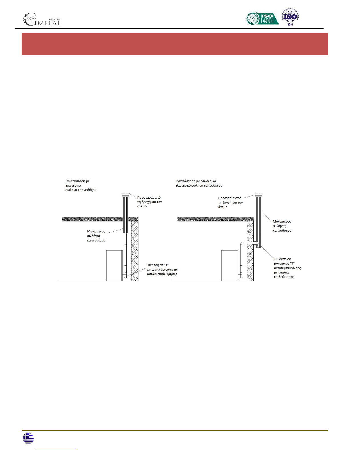
The placement of the fumes extraction pipes Φ80mm can be achieved whether on an installation with existing chimney (minimum surface 200cm² and with an inspection
chamber on the for annual cleaning), or on an installation without existing chimney, with the use of a tee pipe (with cap) connection. The line horizontally reaches the outside
of the building. Then, the chimney, which is fully insulated and has windbreak cap, stands vertically. All the connections should be sealed.
Fumes extraction system belonging to another appliance cannot be connected to the chimney of this appliance.
AIR INTAKE SYSTEM INSTALLATION
The appliance should be capable of using the necessary air to ensure proper function through external air pipes.
With air intake directly from the outside through a pipe (Φinternal 38mm and length max 1,5 m) connected to the special air reception that exists on the back side of the
appliance. A downward bow should be placed on the opening of the pipe on the outside for protection against wind. The air intake can be achieved directly from the
installation area, under the condition that on the wall near the appliance an air intake has been created which communicates with the outside of the building, with minimum
80 cm².
In both cases regular check should be performed, in order to ensure that nothing obstructs the air flow.
INSTALLATION OF SWIVEL OF FUMES RECEPTOR
The fume swivel or receptor that is required for the installation should be designed in such way in order to allow the proper gaslight connection between the fume linkage
and the appliance. The plug or receptor should provide good adjustment for the size of the pipe which is suggested by the constructor. When the linkage is adjusted over an
exit cotter the coating should have length, at least 25 mm for pipes with diameter 160 mm or less, and at least 40 mm for pipes with diameter bigger than 160 mm. In case
the fume linkage does not fit in a receptor, the depth of the insertion should be at least 25 mm .
The adjusters intended for the increase of the flue cotter/receptor diameter are allowed if they are part of the pellet stove. They should be tightly connected and fit with
every flue connection.
NOTE The sealing of the internal connections with heat resistant material or/ and rope, if needed, is suggested.
CONNECTION TO ELECTRIC NETWORK
Before the connection of the appliance to electric network check if the electrical installation is equipped with ground and differential switch, according to regulations.
Connect the appliance to an electric plug of 230v –50Hz voltage, avoiding the use of adaptors, multiplugs and extension.
Make sure that the connection wire does not make contact with warm parts of the heater, and, moreover, it is not subjected to any damage.
We remind you to always unplug the heater before performing any kind of maintenance or check.
TECHNICAL DOCUMENTATION OF INSTALLATION
When installation is finished, the installer should hand over, according to regulations, the compatibility statement of the installation to the owner of the appliance or his
representative. The compatibility statement concerns:
1) the manual of use and maintenance of the appliance and the installation constituents
2) installation manual (if expected).
We suggest the installer to request proof of documentation and save it, along with a copy of the technical documentation concerning the installation.
Installation performed by other persons
If the individual stages of the installation have been performed by different persons, each one should document the stage of the installation he/she performed for the benefit
of the costumer and the person responsible for the next stage.
3.FUMES EXTRACTION SYSTEM
GENERAL REQUIREMENTS
The generator functions under pressure and carries an extraction fan for the removal of the flue gas. Each appliance should be connected to a fumes extraction system and
ensure the proper distribution of combustion products in the atmosphere. The discharge of the combustion products should be on the roof. The direct discharge on the wall
or towards closed areas, even with an open roof, is forbidden. Specifically, the use of flexible extended metal pipes is not allowed. The fireplace should be discharged through
a fumes channeling pipe connected to the appliance. Therefore, the use of collective pipes or the placement of extractor hoods over the grate or the fumes channeling pipes
is not allowed. The fumes channeling pipe and the fireplace should constantly be connected, so that the grate does not touch the appliance. The placement in the internal of
the fumes extraction system of other pipes and airways, even of big size, is not allowed.
The constituent parts of the fumes extraction system should be chosen depending on the typology of the appliance which is to be installed, according to:
EN 14785 : 2006

AIR HEATER PELLET STOVE BY GEKASMETAL
Page 9
Temperature class,
Pressure class (leaktightness) which should be equal, at least to the required leaktightness of the appliance
Moisture resistance,
The class or stage of corrosion and the specifications of the material of the internal wall which contacts the fumes.
Soot fire resistance class
Minimum distance from combustible materials
If the temperature of the generator reaches less than 160οC+ temperature of environment, due to high efficiency λόγω (read technical characteristics) it should
have moisture resistance.
The installer of the fumes extraction system, after finishing the installation and having performed the respective inspections and verifications, should firm, in an apparent
way, near the fireplace plate provided by the constructor along with the product, which should be placed according to the following information:
Nominal diameter
Distance from combustible materials, which is indicated in mm and is accompanied by the arrow and fire symbol
Installer and installation data
Every time they have to cross flammable materials the above instructions should be followed:
SYMBOL
DESCRIPTION
HEIGHT(mm)
b
Minimum distance from combustible materials from the inside of the του
ceiling/floor/wall
500
B
Minimum distance from combustible materials from the outside of the ceiling/floor
500
a
Minimum distance from combustible materials defined by the constructor
1500
You are allowed to deviate from the height Αonly in case you are using an appropriate heat protection screen for the inside of the ceiling/floor
FLUE
General requirements
The flues must be placed under the following conditions:
They should have at least one leaktight provision for potential fumes sampling
They should be insulated if they cross areas not intended to bet heated or the outside f the building
They should not cross areas in where the installation of combustion appliances is forbidden, or other areas that are insulated from fire or in risk of fire, or/and
areas that are not inspected
They should be placed in such way, in order to allow regular thermal dilations
They should be attached on the opening of the fireplace without protruding inside it
The use of flexible metal pipes for the connection of the appliance is not allowed
Sections with opposite inclination are not allowed

AIR HEATER PELLET STOVE BY GEKASMETAL
Page 10
The flues should have, across their length, diameter no less than that of the connection of the extraction pipe of the appliance. Possible changes are allowed only
on the entrance of the stove
They should be placed in a way that the formation of concentrate is controlled and the leakage from the connections is
They should be placed in distance from combustible materials no less than the one mentioned in the description of the product
The flue/pipe should allow the retrieval of soot, it should be cleaned and be inspected after being dismantled or through the inspection openings if it is not
accessible from the inside of the appliance
ADDITIONAL REQUIREMENTS FOR APPLIANCES EQUIPPED WITH ELECTRIC FAN FOR FUME DISCHARGE
For appliances which produce heat with electric fans for fume discharge, the instructions below should be followed:
The horizontal sections should have a slight inclination of 3% upwards
The length of the horizontal section should be minimum and in no case more than 3m
The number of the direction changes, including the use of a tee pipe, should not exceed 4.
EXAMPLES OF CORRECT CONNECTION

AIR HEATER PELLET STOVE BY GEKASMETAL
Page 11
The use of sealing pipes is mandatory
FIREPLACE
Fireplaces, for the release of combustion products in the atmosphere, apart from the general requirements that are defined, they should:
Function with negative pressure (positive pressure is not allowed),
Have an internal section, preferably circular. The square or rectangle sections should have angles rounded to radius no less than 20 mm (hydraulic sections can
equally be used if the ratio between the biggest and the smallest side of the rectangle, that surrounds the same section, is no more than 1,5),
Be used exclusively for fumes emission,
Have mainly vertical route and not have any twist along their length
Not have more than two direction changes with angle no more than 45°
Have, in case of wet function, an appliance for the draining of liquid waste (concentrate, rain water)
PIPE-IN-PIPE SYSTEM
A pipe-in-pipe system can be constructed with one or more pipes for piping which functions only with negative pressure in relation to the environment and should be
according to EN 14785 (2006)
Flue terminals
The flue terminals should comply with the following requirements:
They should be set up in order to obstruct rain and snow penetration in the pipe system,
They should have a practical exit section no smaller than twice as the pipe-in-pipe system in which it has been inserted
They should be constructed in a way that, even in case of strong winds of all directions and inclination, the emission of combustion products is ensured
They should not have assistant inflow mechanisms
COMBUSTION PRODUCTS MOUTH HEIGHT
The height of the mouth is determined by calculating the minimum height that intervenes between the roof top and the lower fume exit section. This height should be out of
the exchange area and in an appropriate distance from obstacles which may obstruct or make the fume discharge hard or from openings or access areas.
Exchange area
The height of the mouth should be out of the exchange area, calculated according to the instructions mentioned below. In proximity to the ridge it is considered the smaller
of the two.
Area for the height of the mouth

AIR HEATER PELLET STOVE BY GEKASMETAL
Page 12
a
c
b
90°
Area for the height of the mouth with inclination ( ß >10°)
REFERENCE
DESCRIPTION
DISTANCE IN mm
c
Calculated distance 90° from the roof surface
1300
a
Height over the ridge of the roof.
500
The mouth of a pipe-in-pipe system should not be near obstacles that may create swirling zones or obstruct proper fume discharge and roof maintenance activities. Check for
other ridges or skylights and attics.
PRODUCT REQUIREMENTS FOR THE FUME EXTRACTION SYSTEM
Temperature class
In case o a pellet appliance temperature classes lower than T200 are not allowed.
Soot fire resistance class
For the fume extraction system, which is controlled by appliances that use solid fuel, soot fire resistance is required. Therefore, the definition should be set with the letter G
accompanied to the distance from combustible materials in mm. (according to EN 14785 (2006)
In case of pellet appliances the fume extraction systems should have leak-tightness, if they use elements of double definition (G and O, with or without elastomeric sealing).
For the connection of the appliance with the fireplace, minimum speed XX in mm should be kept, defined by G. In case of soot fire, make sure you will restore initial
conditions (replacement of gaskets and other damaged components and cleaning of those still appropriate for use).
Ignition testing
The operation of the appliance should be controlled with ignition testing, or
For appliances with mechanical supply, the ignition phase should be finished. Proper function should be verified for at least the next 15 minutes, as well as proper
deactivation,
For appliances inserted in an installation of heating with hot water (thermal fireplaces, thermal stoves), inspection should be performed on the total hydraulic
system.
Coatings and finishings
Coatings and finishings should be applied only after proper function of the appliance has been verified, according to the defined ways.
4. CLEANING AND MAINTENANCE

AIR HEATER PELLET STOVE BY GEKASMETAL
Page 13
According to article 2 No. 37 of the decree of 22nd January 2008 regular maintenance includes interventions intended to minimize the damage of normal use, as well as
troubleshooting of accidents which induce the need for first interventions. These interventions do not alter the structure of the installation or the target of use, according to
the requirements of current technical regulations and the manual of use and maintenance provided by the constructor.
All the cleaning operations of all components should be performed when the appliance is cold and unplugged.
The product requires minimum maintenance, if certified (high quality) pellets have been used.
Daily or weekly cleaning is being performed by the user before each start up.
Clean the ashes and possible aggregations in the “cup” that could clog air passages.
The “cup”, in order to be cleaned properly, should be completely removed from its position and taken off the rack. Clean all the holes and the rack.
Clean and empty the ash tank daily, being careful with the hot ash. Only if the ash is completely cold you can use the vacuum cleaner to remove it.
The glass should be cleaned using a dry cloth. If needed, you can use water and a soft detergent, only if the glass is cold.
Once in a month, clean the area behind the ash tank by removing the cap (photo). To remove the cap, unscrew the 2 screws after you have removed the left side.
Clean with vacuum cleaner. Before operating the appliance, place back the cap.
Below you can find a summary of the necessary inspections or/and maintenance for proper function of the product.
ΤΜΗΜΑ \ ΧΡΟΝΟΣ
DAILY
2-3 DAYS
30 DAYS
90 DAYS
YEARLY
CUP
#
ASH DRAWER
#
GLASS
#
FUME PIPES
#
CHIMNEY COMPONENTS
#
BACK ASH TANK
#
DOOR ROPE
#
CHIMNEY
#
Yearly professional maintenance is definitely suggested.
Inspection and maintenance report
After the completion of the inspection or/and maintenance activities, a report should be composed and given to the owner or his/her representative, who should confirm the
receipt in writing. The report should mention the troubleshooting, interventions performed, possible replaced or placed components, as well as possible remarks, suggestions
and requirements.
The report should be kept along with the documentation.
The inspection and maintenance report should mention the above:
Detected abnormalities which have not been restored and place the safety of the user in danger or may cause serious material damages.
Component parts which have been altered.

AIR HEATER PELLET STOVE BY GEKASMETAL
Page 14
In case of detection of abnormalities the owner or his/her representative, should warn in writing, in the maintenance report, for the unsuitability of use of the appliance, until
the restoration of safety conditions.
The inspection and maintenance report should mention information related to the technician or company that performed the actions of inspection or/and maintenance,
along with contact information, date and signature of the technician.
5. TECHNICAL CHARACTERISTICS
MODEL
WOOD PELLET STOVE AMANDA
DIMENSIONS (HxWxD)
971x462x529 mm
FUME EXIT (Φ)
80 mm (backside)
HEIGHT FROM FLOOR TO THE CONNECTION WITH FUME EXTRACTION PIPE
100 mm
VOLTAGE
230 V
NOMINAL POWER
2,5kW / 5kW / 8,5kW
MAXIMUM EFFICIENCY
89%
WEIGHT
114 kg
CO CONCENTRATION (REDUCED TO 13% O2) PELLET
320PPM
FUME TEMPERATURE
169,3 °C
MINIMUM CONSUMPTION
0,55 kg/h
MAXIMUM CONSUMPTION
1,85 kg/h
971
465
971
529
529
465
6. HANDLING

AIR HEATER PELLET STOVE BY GEKASMETAL
Page 15
CONTROLLER comes separately (unedited) with two screws. You place it on its base, on the top of the stove, with the assistance of a “key”
1. ON/OFF(ESC) button
Single press:
- Activates the boiler,
- Within a menu, it causes exit from menu.
- During the processing of a value, it causes exit without recording the value.
- During the processing of text, it causes exit without recording the text.
Prolonged press:
- Switches off the boiler performing all necessary actions (ignition, combustion chamber cleaning etc.)
2nd prolonged press:
- Switches off and deactivates the boiler.
2. MENU(◄) button
Single press:
- Opens the user menu (Settings).
- Within a menu, it causes exit from menu.
- During the processing of a value, it causes exit without recording the value.
Prolonged press:
- Opens the settings options menu.

AIR HEATER PELLET STOVE BY GEKASMETAL
Page 16
3. Plus Button (+)
Increase and navigation button
Single press:
- Enables the screen for room temperature settings.
- Within a menu, it causes scroll up.
- During the setting of a value, it causes increase of the value.
- During the selection of a value from a list, it causes scroll up.
Prolonged press:
- Enables the fast operation power setting screen (Automatic, Scale 1, Scale 2, Scale 3).
- Combined with Minus (-) button, it changes the current indications screen (Main Screen, Entries Screen, Exits Screen).
4. Minus Button (-)
Decrease and navigation button
Single press:
- Enables the screen for room temperature settings.
- Within a menu, it causes scroll down.
- During the setting of a value, it causes decrease of the value.
- During the selection of a value from a list, it causes scroll up.
Prolonged press:
- Enables the fast operation power setting screen (Automatic, Scale 1, Scale 2, Scale 3)
- Combined with Plus (+) button, it changes the current indications screen (Main Screen, Entries Screen, Exits Screen).
5. ENTER(►) button
Confirmation button
Single press:

AIR HEATER PELLET STOVE BY GEKASMETAL
Page 17
- Within a menu, it selects and opens the specific menu.
- During the processing of a value, it records the value.
Prolonged press:
-In case the fuel storage is completely empty, it will empty the combustion chamber, resulting in the appearance of an error message, if the user attempts to refill it with the
pressing of the ON/OFF(ESK) button . Prolonged press of the ENTER button when the system is in <SHUTDOWN> phase or <INERTIA> phase, enables the fast activation of
inspection operation of supplier speed screen, and it will supply the combustion chamber with fuels (pellets) operating for 1 minute and 45 seconds without combustion.
6. Screen
The screen where all the information and menus of the boiler appear. The screen can be disabled after a regulated time. If disabled it returns with the pressing of any button.
In this case the normal function of the button is ignored.
7. Operation indicator
Switches on when boiler is operating. That is when start up is executed or there is fire in the combustion chamber.
8. Consumption indicator
Switches on when a selected fan is enabled.
9. Thermostat indicator
Switches on when an external thermostat is enabled.
10. Alert indicator
Does not concern this specific appliance!
11. Error indicator
Switches on when there is an error.
Activation –Deactivation
The control system, as long as it runs, is always at an operating phase. In order for the appliance to function and the control system to be at an operating phase it should,
firstly, be activated. The control system is considered activated when it is at any phase, except for the phase <SHUTDOWN>. If it is deactivated, the indication on the screen is
”SHUTDOWN”. If it is activated the indication on the screen is the particular phase which is being executed that moment .The control system can be activated and deactivated
in many ways depending on actions of the user, the formulation of the system or an error. Specifically,
If it is disabled, it is enabled with:
<ON/OFF(ESC)> button single press.
Then the control system moves to <INERTIA> phase.
In case the start up is disabled, then the control system bypasses inertia and moves directly to start up –operation (Initial cleaning-pre-heating-etc).
If it is enabled, it is disabled with:
<ON/OFF(ESC)> button prolonged press.
In this case the control system moves to <SHUTDOWN> phase, only if there are no fuels in the combustion chamber. If there are, then it returns to <SHUTDOWN> phase,
after executing full start up and shutdown, without holding. When this happens on the screen appears the indication “SWITCH OFF”for 5 sec. To disable control system hold
down the <ON/OFF(ESC)> button for a SECOND time.
Errors, like sensors errors. After detection/ restoration of such errors, the control system moves to <SHUTDOWN> phase.
During switching off, it is disabled with:
<ON/OFF(ESC)> prolonged press.
The control system state is being preserved during power cut. That means if the control system is enabled a power cut occurrs, when the system resumes and there is no fire
in the combustion chamber, the controller will move to <INERTIA> phase instead of <SHUTDOWN>.
All errors do not lead to <SHUTDOWN> phase.(Consult errors).
START UP AND OPERATION PHASES

AIR HEATER PELLET STOVE BY GEKASMETAL
Page 18
After you connect the appliance to electric current, turn the switch, on the back of the appliance, on position 1. On the screen the following appear:
Name - type of the appliance and operation program (i.e. Air 1).
With the application of electric power voltage the appliance performs a CHECKING in case there is fire in the combustion chamber. On the screen appears the following
image:
If there is fire and the fume temperature is higher than the temperature of ”Down Error”, then the appliance starts automatically and moves to <OPERATION> phase,
without saving activation to the memory.
If there is fire and the fume temperature is lower than the temperature of ”Down Error”, then the appliance moves to the <FINAL CLEANING> phase, if existing, and then to
the <INERTIA> phase, without saving activation to the memory.
If there is no fire, then the controller moves to the <INERTIA> phase or the <SHUTDOWN> phase, depending on whether it was enabled or disabled before the interruption of
electrical supply voltage.
During the first ignition, it is possible that the appliance will move to the <SHUTDOWN>phase, due to required quality inspections and testings that have been performed in the
factory.
Holding down the ON/OFF(ESC) button the operation phase appears on the screen:
<INITIAL CLEANING>
During this phase the appliance uses the combustion fan to clean the combustion chamber from remaining materials. The combustion chamber fan operates in this phase.
Then, the appliance, automatically, moves to operation phase:
<PRE-HEATING>
During this phase the ignition resistance is being enabled, in order to prepare the next phase.
<FUELING>
During this phase the fueling of the combustion chamber with pellets is being enabled, in order to create a stock for the ignition. Ignition resistance is enabled.
<FLAME HOLD>
The appliance enters this phase after fueling. The control system remains in this phase for some time.

AIR HEATER PELLET STOVE BY GEKASMETAL
Page 19
During this time, if the appliance perceives flame existence, then it moves to <PRE-OPERATION> phase. Otherwise, startup is being terminated and error E20 appears on the
screen.
The appliance perceives the existence of flame if there is fume temperature increase.
<PRE-OPERATION>
During this phase the preparation of flame occurs, so that in the next phase which is <OPERATION> phase, the flame will be satisfactory. Moreover, during this phase the
initial stock, created for the ignition, is being burned. Ignition resistance is disabled.
<OPERATION>
Automatically
During this phase the boiler operates with the control system enabled. The speed of the power supplies and the combustion fans are adjusted automatically, in order to
achieve the desirable operation temperature.
Manually
When a manual program has been selected, then the control system is not enabled. On the contrary, it operates according to the selected power scale constantly.
The power value for each scale is regulated by the settings:
“Power scale 1” for scale 1
“Power scale 2” for scale 2
“Power scale 3” for scale 3
The appliance uses this value to define the current values of combustion fans and power supplies.
<REGULAR CLEANING>
As long as the appliance functions with low power, due to low air flow in the combustion chamber and low temperature, there is cleaning problem. <REGULAR CLEANING> is
a protection measure. The control system enters this phase periodically, while being in <OPERATION>phase, and it remains in this phase for a few seconds. The combustion
fan operates, while the supplier is disabled.

AIR HEATER PELLET STOVE BY GEKASMETAL
Page 20
<CONSTANT HOLD>
When the area temperature equals the one requested (or slightly higher than 0,5οC), then the appliance enters <CONSTANT HOLD> phase for a few minutes. This happens
because a solid fuel system has not the same ignition flexibility as a liquid or gas fuel system. Therefore, a common practice is the attempt for reduction of ignitions. To
achieve this, the control system, after disabling the operation orders, enters a hold phase during which it preserves the flame, so that the return in <OPERATION> phase
would be instant, as soon as an order appears. During this phase the fume inhibitor*is enabled from <OPERATION> phase. The supplier and the combustion fan function
according to electric power of that period. Then it moves to the next phase.
*Fume inhibitor
The electric power of the system in this phase, whether setted automatically or manually, is affected by the fume temperature signal, if it is enabled. In this case there is a
system which protects from very high or low fume temperatures. This system is called fume inhibitor. These settings concern some temperature limits which, if the fume
temperature signal exceed, the control system starts increasing or decreasing its power in order to reset the fume temperature within the limits. This operation may better be
explained through an example.
<FINAL CLEANING>
During this phase the control system cleans the combustion chamber, in order to be empty for the next ignition.
The control system remains in this phase for a specific time period. If, during this time period, the fume temperature drops below the “deactivation temperature”, then the
phase is being terminated and the controller moves to <INERTIA> phase.
The combustion fans, during the entrance of the control system in this phase and for a small period of time, preserve their former speed. After this period of time and for the
rest of the phase the combustion fan functions with maximum speed. The supplier is being disabled.
7. ERRORS
Error codes
Description
Cause
Function
E01
Memory failure
Malfunction of the control system.
• The system fails to start up and all functions remain disabled.
• This error CANNOT be disabled.
• If the error is not permanent, the controller restarts after reset
of voltage supply.
Ε05
External error
The entry signal contact external error
has been opened.
• The boiler is being deactivated.
• The exit functions remain activated.
•The entry signals remain activated.
• The system does not return in function if the error has not been
removed by the user.
Ε11
Area Sensor 1
Area temperature 1 sensor is
disconnected, shorted or open.
• The boiler is being deactivated.
• The exit functions remain activated.
• The remaining exit functions are being disabled.
• The entry signals remain activated.
• The system does not return in function if the error has not been
removed by the user.
Ε13
Fume Sensor
Fume temperature sensor is
disconnected, shorted or open.
•The boiler is being deactivated.
• The exit functions remain activated.
• The remaining exit functions are being disabled.
• The entry signals remain activated.
• The system does not return in function if the error has not been
removed by the user.
Ε15
Speeds sensor
The combustion fan does not function or
the speeds sensor presents failure.
• The boiler is being deactivated.
• The exit functions remain activated.
•The remaining exit functions are being disabled.
• The entry signals remain activated.
• The system does not return in function if the error has not been
removed by the user.
Ε20
Startup Failure
During <FLAME HOLD> phase fume
temperature failed to be increased as
much as needed, within the time limits of
• The boiler is being deactivated.
• The exit functions remain activated.
•The entry signals remain activated.
Table of contents
Popular Pellet Stove manuals by other brands

Extraflame
Extraflame Comfort P70 user manual

Harman
Harman P43 user manual

Pelpro
Pelpro PPC90 user manual

Quadra-Fire
Quadra-Fire CASTILEI-MBK Owner's manual installation and operation

Piazzetta
Piazzetta P963 THERMO Instructions for installation, use and maintenance

MCZ
MCZ EGO-STAR Hydromatic 12 installation guide

EdilKamin
EdilKamin BERING Installation, use and maintenance

Drolet
Drolet ECO-65 Installation and operation manual

Extraflame
Extraflame Comfort Mini user manual

Natures Flame
Natures Flame EcoChoice PS35 Installation specification sheet

Kstove
Kstove EN 14785 Instructions for use

Comfort Bilt
Comfort Bilt HP60I Operator's manual