Gelec ALLS6000 User manual

ANALOG LIQUID LEVEL SENSOR
ALLS6000
INDUSTRIAL ELECTRONICS

User’s & Technical Manual – ANALOG LIQUID LEVEL SENSOR ALLS6000
GELEC Industrial Electronics PAGE 2

User’s & Technical Manual – ANALOG LIQUID LEVEL SENSOR ALLS6000
GELEC Industrial Electronics PAGE 3
CONTENTS
1. PRECAUTIONS!..................................................................................................................................................................................4
2. MANUFACTURER’S WARRANTY, GENERAL TERMS AND CONDITIONS....................................................................5
3. DISPOSAL OF OLD ELECTRICAL & ELECTRONIC EQUIPMENT .......................................................................................6
4. ANALOG LIQUID LEVEL SENSOR ALLS6000 ..........................................................................................................................7
5. GENERAL DESCRIPTION ................................................................................................................................................................8
6. ALLS6000 VERSIONS AND OPTIONAL PARTS ......................................................................................................................9
7. CONTROL UNIT ALLS6000......................................................................................................................................................... 11
8. PNEUMATIC SECTION ................................................................................................................................................................. 11
9. ELECTRICAL SECTION .................................................................................................................................................................. 14
10. OPERATING PHILOSOPHY –LEVEL DESCRIPTION........................................................................................................... 16
11. LEVEL CALIBRATION PROCEDURE.......................................................................................................................................... 19
12. FILLING / DRAINING OPERATING MODES.......................................................................................................................... 20
13. INSTALLATION................................................................................................................................................................................ 22
14. ELECTRICAL CIRCUIT DIAGRAM .............................................................................................................................................. 23
15. AIR CIRCUIT DIAGRAM ............................................................................................................................................................... 24
16. DIMENSIONS .................................................................................................................................................................................. 24
17. TECHNICAL SPECIFICATIONS ................................................................................................................................................... 25
18. DECLARATION OF CONFORMITY ........................................................................................................................................... 27

User’s & Technical Manual – ANALOG LIQUID LEVEL SENSOR ALLS6000
GELEC Industrial Electronics PAGE 4
1. PRECAUTIONS!
There are no serviceable parts inside the ALLS6000 unit. Not to be opened by any
unauthorized person. All repairs to the device must be carried out by the manufacturer.
Improper handling may result in serious personal injury and considerable material
damage. All connection and maintenance work must be carried out by qualified personnel.
RISK OF ELECTRIC SHOCK!
Use the correct voltage. The ALLS6000 is designed for use
with specific voltage only. Connection to a different voltage
may cause fire, electric shock or other damage.
Do not touch the plug and the connectors with wet hands.
Disconnect the ALLS6000 before cleaning it, to avoid the risk of electric shock.
Attempting to use a malfunctioning ALLS6000 can be dangerous.
Do not block the ventilation slots on the cabinet of the ALLS6000.
Keep liquids away from the ALLS6000.
Spillage into the cabinet may result to fire, electric shock, or equipment damage. If a small
object or liquid falls/spills into the ALLS6000 cabinet, unplug the unit immediately. Have the
unit checked by a qualified service engineer before using it again.
Set the ALLS6000 in an appropriate location.
Do not install in a dusty, humid, or vibrating environment. Do not place it near heater, or air
conditioner. Keep it away from air, steam, extremely high or low temperature or humidity.

User’s & Technical Manual – ANALOG LIQUID LEVEL SENSOR ALLS6000
GELEC Industrial Electronics PAGE 5
2. MANUFACTURER’S WARRANTY, GENERAL TERMS AND CONDITIONS
Thank you for purchasing our product.
Our products have been manufactured with the latest technology, the highest quality
components and have gone through rigorous quality control tests at the factory, before
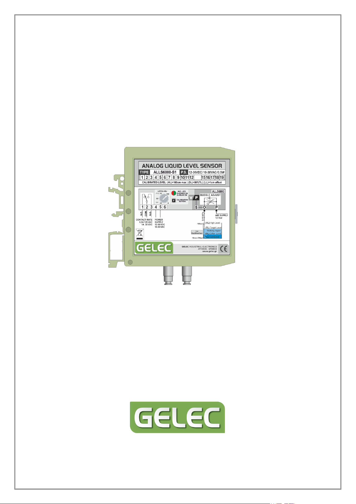
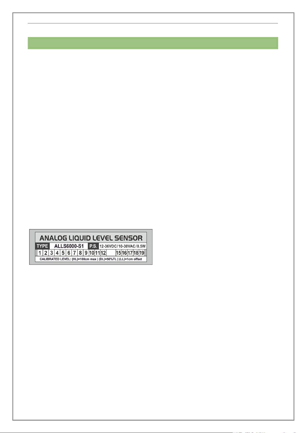
shipment. Make sure that the part number and type indicated in the identification label and
pack correspond to the part number or type of your order. After receiving, inspect the unit
to ensure that no damage have been caused during transportation.
GELEC and GELEC’s authorized distributors warrant to the original purchaser that the
product shall be free from defect in material and/or workmanship. The warranty period
begins on the purchase date (proof of purchase by invoice or delivery note) and is valid for
one (1) year. The guarantee period begins on the sales date (proof of purchase by invoice
or delivery note) and is valid for 1 year.
In the event of malfunction during the warranty period attributable directly to faulty
material and/or faulty construction and functional defects, GELEC and authorized
distributors will, at their option, either repair or replace the faulty product with the same or
similar model.
GELEC and authorized distributors shall have no obligation under this warranty, however, in
the following cases:
Any defect caused by freight damage, accident, disaster, faulty maintenance or
improper handling.
Any defect caused by modification, alteration, abuse, misuse or incorrect installation.
Any defect of the product caused by improper repair by third party other than GELEC
and GELEC's authorized distributors.
Any incompatibility of the products with subsequent technical innovations or
regulations.
Any defect of the product caused by external equipment.
Any defect of the product on which the original manufacturer’s labeling has been
altered or removed.
In case of complaint please contact our company or send the unit un-dismantled to your
local dealer. Any necessary replacement parts and necessary repair work are totally covered
free of charge.
All products are designed and produced by the manufacturer GELEC Co. Ltd to be in
compliance with the EU norms applying to them. GELEC is not responsible for direct or
indirect damages or malfunction caused by improper use or installation of the ALLS6000.

User’s & Technical Manual – ANALOG LIQUID LEVEL SENSOR ALLS6000
GELEC Industrial Electronics PAGE 6
3. DISPOSAL OF OLD ELECTRICAL & ELECTRONIC EQUIPMENT
- Applicable through the EU and other European countries with separate collection programs -
This symbol, found on your product, indicates that this should not be
treated as household waste when you wish to dispose it.
It should be handed over to an applicable collection point for the
recycling of electrical and electronic equipment.
By ensuring this product is disposed of correctly, you will prevent
potential negative consequences to the environment and human
health, which could otherwise be caused by inappropriate disposal of this product.
The recycling of materials will help to preserve natural resources.

User’s & Technical Manual – ANALOG LIQUID LEVEL SENSOR ALLS6000
GELEC Industrial Electronics PAGE 7
4. ANALOG LIQUID LEVEL SENSOR ALLS6000
This operator's manual explains the functions and operation of the ALLS6000. It also gives
some troubleshooting tips as well as general precautions to be taken when operating the
unit. In order to ensure the best performance and effective use of the ALLS6000, we
recommend that you read the information in this manual carefully and follow the
instructions contained.
This manual is a complete guide to the ALLS6000 with information on unit user
maintenance, unit installation and instructions on how to operate it. Do not touch any part
of the ALLS6000 the manual does not cover. Keep the manual for immediate reference. It
should help in solving any operational questions you may have.
No part of this manual may be quoted, reproduced, stored in a retrieval system,
transmitted, transcribed or translated into any other language in any form or by any means,
electronic, mechanical, or otherwise, without prior written permission of “Gelec Co. Ltd”.
Although every effort has been made to ensure that this manual provides up to date
information, please note that the contents in this manual and the unit specifications are
subject to change without notice.
Do not forget to refer the exact type and
version of your ALLS6000 whenever you
contact the manufacturer, asking for any
further information. You can find this
information on the identification label on
the side of the unit.

User’s & Technical Manual – ANALOG LIQUID LEVEL SENSOR ALLS6000
GELEC Industrial Electronics PAGE 8
5. GENERAL DESCRIPTION
The ALLS6000 is a programmable electronic device used for liquid level control between a
desirable region, in open tanks of height from 10 cm up to 500 cm, with analog sensor and
digital output. Its operation is based on the measurement of the hydrostatic pressure of
liquids. This device requires external air supply in order to function using this method.
fig. 1
fig. 2
The pressure that rises at the unit’s outlet (O-S) is proportional to the hydrostatic pressure
of the controlled liquid in the tank. An internal sensor measures this pressure and
transforms it to voltage. Afterwards, several electronic circuits and a microcontroller process
this signal and depending on user adjustments, a digital command is taken when the liquid
in the tank reaches the selected target level (TL). The outcome is the fluctuation of the level
into a desirable working region (between a Target Level and the Differential Level). (fig. 2)
MAIN FEATURES
Precise measurement and level control in open tanks.
Programmable selection of FILLING/DRAINING operating mode.
Level control in tanks with foam and variety of liquids (acidic, alkaline etc.)
Suitable for tanks where danger of explosion exists.
Control in open tanks without the danger of sensor damage from falling water.
Programmable selection of High, Low and Differential control levels.
On-board knob for the Target Level tuning. (External potentiometer optional)
Customized versions available.
DIN NS32/NS35 mounting.

User’s & Technical Manual – ANALOG LIQUID LEVEL SENSOR ALLS6000
GELEC Industrial Electronics PAGE 9
6. ALLS6000 VERSIONS AND OPTIONAL PARTS
ALLS6000-S1 - STANDARD VERSION
●
Mounted potentiometer for level adjustment
●
10kPa air pressure sensor
●
Pre-calibrated High Level at 100 cm of clear water
(Programmable High Level at points lower than 100 cm)
●
Pre-calibrated Low Level at 1cm of clear water (offset)
(Programmable Low Level at points higher than 1cm)
●
Differential Level at 50% of the Target Level,
programmable between 1cm and 100cm
●
Built-in air flow regulator
●
Air pipe connectors (4-6 mm)
ALLS6000-Sx- CUSTOMIZED VERSION
The device can be customised to your application with the following:
●
External potentiometer for the Target Level adjustment
●
Air pressure sensor range from 10kPa to 150kPa
●
Pre-calibrated High Level at 100 - 1500 cm clear water
(Programmable High Level at lower than the pre-calibrated
point)
●
Pre-calibrated Low Level at a point higher than 1cm of clear
water (offset) (programmable Low Level at higher than the
pre-calibrated point)
●
Pre-calibrated Differential Level at any desirable level
between the Low and the High Level)

User’s & Technical Manual – ANALOG LIQUID LEVEL SENSOR ALLS6000
GELEC Industrial Electronics PAGE 10
- OPTIONAL PARTS -
Air Pressure Regulator
Air Pump
Fixed Air Pump for 1m of water supplied
with 5V DC and 250 mA power ( 1,25 W )
2000 hours maximum working life in full operation.
Air Items
Type M5 4-6mm Connectors
Air Pipe
Nylon air pipe (4-6) mm (inner - outer)
Deflation Tube
Ø=12mm outer diameter and 120cm length
deflation tube divided in two pieces, with connection.
fig. 3
fig. 4
fig. 5
fig.6
fig.7
2.5b ar
AIR IN LET
AIR SOURCE
MAX PRESS URE
10kPa ( 1.45psi)
POWER
SOURCE
5V DC
GCPI P5000
1 2 3 4 5 6 7 8 9 10 1112 0607 080910
10kPa PU MP
TYPE GCP IP5000 P.S. 5V DC / 1.25W
Max PRESSURE LEVEL: 10kPa (1m of WATER)
ZISIS G OU GOU TOU DIS C . LO TD
ATHE NS – GREEC E
INDUSTR IAL E LECTRON IC S
WWW .GE LEC.G R

User’s & Technical Manual – ANALOG LIQUID LEVEL SENSOR ALLS6000
GELEC Industrial Electronics PAGE 11
7. CONTROL UNIT ALLS6000
The ALLS6000 is a complete unit with built-in
electric connection terminals, electronic board,
air flow regulator, adjusting level knobs, a
calibration button and air pipe connectors, in
light green box, suitable for electronic devices,
and DIN rail mounting. The unit is made to be
installed at the inside of an electrical control
panel, placed on a mounting rail of Ω type
(NS32/NS35).
8. PNEUMATIC SECTION
DEFLATION TUBE
A thin deflating tube should be clamped on the wall of the tank with
its nozzle immersed into the liquid. A small quantity of air is
provided to the tube via air pipes and deflates into the liquid in a
form of bubbles.
The deflation tube must have a 60oV-cut at the bottom for proper
air deflation and a pipe connector on top of it, for the connection
with the (S-O) pipe. The active height in which you will have the
measurement is 100cm, but the top of the tube must be at least
20cm above the level for avoiding liquid suction.
The tube may be as long as you need, according to your application,
although notice that the liquid level must not exceed the maximum
level of 1.5m because this may damage the air pressure sensor.
The tube diameter should be from Ø10mm to Ø30mm, as the device calibration has been
done in an average Ø20mm tube. You can use a tube with different dimensions, but notice
that you may have to adjust the air flow regulator.
fig. 8
fig. 9

User’s & Technical Manual – ANALOG LIQUID LEVEL SENSOR ALLS6000
GELEC Industrial Electronics PAGE 12
We recommend the usage of a tube with Ø9mm inner and Ø12mm outer diameter, which
is appropriate for a 1/8 screw thread, in order to screw the connector (T-shaped) connector
without further modification.
You should pay extra attention at the connections of the pipes,
because any leakages degrade the measurement.
In order to avoid air leakage, use a thread seal tape PTFE®or an
anaerobic adhesive to seal up the thread connectors. Screw the
pipe connector as in the connection drawing. Finally, clamp the
tube firmly in the liquid tank in an upright position.
The unit must not be installed in height lower than the (HL).
AIR PIPE CONNECTIONS
At the bottom of the ALLS6000 there are 2
pipe connectors of 4-6 mm. Polyurethane or
nylon pipes are suitable for these connectors.
Maintain the air purity in an acceptable level.
Dusty and polluted air makes the pipes dirty
and high level of humidity or oil will damage
the sensor.
The (P) is the air PRESSURE inlet pipe
connector. The (O) is the OUTLET of the
airflow regulator and the (S) is the SENSOR
Input. The (O) and (S) are internally connected and lead to the tube.
The (P) connector leads the air to the air flow regulator. Supply the (P) connector with an
invariable pressure, which should be higher than the hydrostatic pressure of the tank (e.g.
for tank height 1m it should be 1.5bar / 21psi).
Notice that the OUTLET air flow is very low. Any air leakage along the S and O piping
will cause the discontinuance of the deflation during the liquid level rise, affecting the
measurement.
The hydrostatic pressure is applied at the S/O connector in order to be measured from the
pressure sensor. If the sensor-applied pressure is higher than the specifications, the sensor
will be destroyed.
Thread sealing
adhesive
fig. 10
fig. 11

User’s & Technical Manual – ANALOG LIQUID LEVEL SENSOR ALLS6000
GELEC Industrial Electronics PAGE 13
AIR FLOW ADJUSTMENT
Air Flow controls the amount of air which deflates from the tube
into the tank. The recommended air flow for an accurate
measurement is pre-adjusted by the manufacturer and user
adjustments are not recommended. However, if an adjustment is
necessary, it can be done using a flat screwdriver on the knob on
the front right part of the unit (clockwise for less air flow), in order to set the deflating air
flow to 3-4 bubbles/sec.
AIR GAUGE SENSOR
The ALLS6000 has a single, monolithic silicon diaphragm, piezoresistive strain gauge sensor
chip, providing a highly accurate and linear output directly proportional to the applied
pressure. On-Chip Temperature Compensated & Calibrated, this Silicon Pressure Sensor is
laser trimmed for precise span and offset, bias equalized with the Atmospheric pressure.
A silicone gel isolates the die surface and wire bonds from the environment, while allowing
the pressure signal to be transmitted to the silicon diaphragm.
The pressure sensor operating characteristics, internal reliability and qualification tests are
based on use of dry air as the pressure media. Media other than dry air may have adverse
effects on sensor performance and long term reliability. Contact the manufacturer for
information regarding media compatibility in your application.
In order for the device to function using this method, air supply (inlet (P)) is required,
with pressure higher than the highest hydrostatic pressure of the container in which
the control is taking place.
Inside the device there is an incorporated air flow regulator with which we regulate
the air flow the (O) outlet. Internally, this outlet is interconnected with the (S) inlet.
We regulate the flow so that, at the sensor outlet (specifically shaped pipe), three to
four bubbles per second are formed.
fig. 12

User’s & Technical Manual – ANALOG LIQUID LEVEL SENSOR ALLS6000
GELEC Industrial Electronics PAGE 14
9. ELECTRICAL SECTION
POWER SUPPLY (Terminals #4 - #5)
The ALLS6000 includes an integrated power supply circuit. The
maximum power consumption is approximately 0.5W in total
operation, with all indicators and relay activated.
Connect the power source with the terminals (4) and (5).The
polarity is not important, as the internal power circuit includes
electronic components for non-polarity connection. When the unit is
powered the indicating led turns red.
The power supply can fluctuate between 10 and 30V Alternative
(~AC) or 12 to 36V Direct (-DC), either regulated or unregulated.
There is not an electrical safety fuse in the internal power circuit.
Connection to a different voltage may cause fire, electric shock or
damage.
DIGITAL OUTPUT (Terminals #1=N.C. - #2=COM - #3=N.O.)
This output (terminals #1-#2-#3)works as a potential contact of a relay. These contacts
allow the operation of the device that fills/drains the tank. The DPDT relay contacts are
potential free (Voltage free common).
The relay’s status changes when the tank level exceeds the set point. When this output is
activated the indicating led turns green.
Any wrong configuration of the relay output connection may cause permanent damage to
the unit.
ANALOG PWM OUTPUT 0..5V (Terminals #9=COM - #6=0…5V) -Optional-
Through this output (terminals #9 - #6)the device gives a signal 0...5V, which is
proportional to the liquid level height. This voltage is linear and corresponds to the
intermediate tank levels from Low Level (LL=0%) to High level (HL=100%).
In order to get the complete voltage scale (VMAX=5V), the load resistance should be above
1MΩ(RL≥ 1MΩ). If the load resistance is smaller than that, VMAX will drop and you should
measure the output voltage value. E.g. for RL=450KΩthe device provides VMAX = 4,5V.
fig. 13

User’s & Technical Manual – ANALOG LIQUID LEVEL SENSOR ALLS6000
GELEC Industrial Electronics PAGE 15
INDICATION LED
The multicolour led at the front of the device the ability to know:
If the device is powered (red colour).
If relay contact is activated (green colour).
If the device is in calibration process, as it is described in the
corresponding chapter.
FUNCTION BUTTON
This programming button is used during the calibration process
and the operating mode selection (FILLNG/DRANINING). Refer to
the corresponding paragraphs.
ON-BOARD POTENTIOMETER (KNOB)
The potentiometer’s position, adjusts the liquid’s Target level (TL)
into the tank. Notice that the 0...100 scale refers to the percentage
of the High Level (HL). Therefore the value that the arrow is
pointing, is the desirable (TL), but as a percentage of the (HL) and
not as an absolute value. The potentiometer’s use during the level
calibration process is described in the corresponding paragraphs.
EXTERNAL POTENTIOMETER (Terminals #7 - #8 - #9)-Optional-
The external potentiometer has the same operation with the on-board knob (which in that
case in not installed) and determines the liquid’s target level (TL) into the tank. The
potentiometer’s use during the level calibration process is described in the corresponding
paragraphs. This feature is useful when frequent Target Level selections are needed, without
interrupting the application process.
OUTPUT +5V (#7)
Connect a potentiometer pin 10-100KΩ(level decrement).
SIGNAL INPUT (TL) 0..5V (#8)
Connect the potentiometer’s variable pin.
COMMON OUTPUT 0V (#9)
Connect the other potentiometer pin 10-100KΩ(level increment).

User’s & Technical Manual – ANALOG LIQUID LEVEL SENSOR ALLS6000
GELEC Industrial Electronics PAGE 16
10. OPERATING PHILOSOPHY –LEVEL DESCRIPTION
The ALLS6000 operating philosophy is based on a desirable
working region and four critical liquid levels (fig. 14), which can be
calibrated from the user to meet his application needs. The levels
and their functionality are described below.
(HL) High Level
It is the highest level the user can select with the potentiometer. You can set this level
following the calibration process.
If the (HL) is modified through the calibration process, the (LL) and the (DL) must also be
modified.
(LL) Low Level
It is the lowest level the user can select with the potentiometer. You can set this level
following the calibration process.
If the (LL) is modified with the calibration process, it is essential for the (DL) also to be
modified to the desirable level.
Working region
It is the desirable region which the liquid level fluctuates, either in FILLING or DRAINING
mode. The working region is between (TL) and (DL), which are can also be calibrated.
(TL) Target Level
It is the desirable level and it can be selected by using the potentiometer’s 0..100 scale.
At the (TL), the relay changes status, and the liquid falls back to the Differential Level
(DL). Notice that the 0...100 scale refers to the percentage of the High Level (HL).
Therefore the value that the arrow is pointing, is the desirable (TL), but as a percentage
of the (HL) and not as an absolute value.
(DL) Differential Level
It is the level which the liquid returns to, after reaching the (TL) and also where the relay
changes its status. (DL) is always lower than the (TL) (pre-selected value 50%(TL)) and the
user can modify it with the calibration process. It is not essential to modify the other
levels after calibrating (DL).
fig. 14

User’s & Technical Manual – ANALOG LIQUID LEVEL SENSOR ALLS6000
GELEC Industrial Electronics PAGE 17
The user can program the (DL) at a desirable level following the calibration process,
without changing the other two level values.
The Differential Level (DL) you select each time is stored in the unit’s memory as a
percentage of (HL). But during operation, the device uses this factor for the calculation of
the (DL) as percentage of the (TL). So if the user selects as (DL) the 25% of the (HL), then
the device will function with (DL) = 25% of the (TL).
DIFFERENTIAL LEVEL CALCULATION - EXAMPLE
Use the below procedure and example as a guide to calculate the differential level you
have to calibrate:
Calculate the differential coefficient (k) between your desirable (TL) and (DL), which are
the two limits of your working region as below:
k = 100 × ( TL – DL ) / TL (1)
And then use k in the following type, to find the liquid level height that you should have
into the tank for the (DL) calibration procedure.
DL = HL - ( HL x k / 100 ) (2)
- OPERATING EXAMPLE -
For example, your application needs the (HL) to be calibrated at 100cm, the (LL) at 0cm
and you want the working region to be between 70cm (DL) and 80cm (TL).
After the calibration of the (HL), (LL), and (TL) you have to calculate the DL before
calibration in accordance with the above types.
In this example the equation (1) becomes:
k = 100 ×( 80-70 ) / 80 = 12.5
And the equation (2) becomes:
DL = 100 - ( 100 × 12.5 / 100 ) = 87,5cm
So, you have to fill your tank with 87,5cm of liquid and then proceed to (DL) calibration.

User’s & Technical Manual – ANALOG LIQUID LEVEL SENSOR ALLS6000
GELEC Industrial Electronics PAGE 18
When the differential level (DL) is calibrated, any target level (TL) selection through the
potentiometer, will lead the device to automatically calculate the working region. At this
example for a (TL) selection of 80cm, the working region will be 80cm-70cm.
Notice that with these example’s steps, for every (TL) you select with the potentiometer,
the (DL) will be 12,5% less.
PRESELECTED VALUES
The standard version ALLS6000-S1 can control the liquid level in tanks with height from
10cm to 100cm and has the below preselected values and parameters.
Liquid : Soft Water
High level (HL) : 100 cm
Differential level (DL) : 50% of (TL).
Low level (LL) : 1cm (0+1cm offset)
NOTES
The device measures the hydrostatic pressure of the liquid contained in the tank, so
the tank’s volume and shape are not factors that influence the measurement.
The calibration is done for a specific tank height and for a specific liquid. If you use
the same tank with a different liquid, a new calibration has to be done.
In order to have the optimum measurement resolution, it is recommended the high
level to be calibrated near the target level.
According to your unit version, take care not to exceed the recommended liquid
level height. If the sensor-applied pressure is higher than the appropriate, the sensor
will be destroyed.

User’s & Technical Manual – ANALOG LIQUID LEVEL SENSOR ALLS6000
GELEC Industrial Electronics PAGE 19
11. LEVEL CALIBRATION PROCEDURE
With this procedure you can calibrate the device to store the required parameters, in order
to function according to the needs of your application. For each level calibration follow the
appropriate steps. The calibration can be done either with the on-board or an external
potentiometer.
After the device installation the calibration process as described below is essential. The
correct level calibrating order is (HL) → (LL) → (DL). This order is important in order to get
the optimum level measurement resolution and the on-board knob’s 0..100 scale to
precisely correspond with the levels (LL) - (HL).
If during the calibrating process there is an idle period of 30 seconds, or the power is
interrupted, the device returns in operating mode with the pre-existed values.
(HL) High Level Calibration
•Fill the tank up to the highest desirable level. (fig.15)
•Press and hold the button until the led starts flashing.
•Turn the potentiometer until you find the area where
the led flashes with green color - a clue that the value
to be registered is the High Level (HL).
•Press and hold the button again until the led turns on
constantly.
✓The High Level (HL) value is registered.
If the (HL) is modified through the calibration process, the (LL) and the (DL) must also be
modified.
(LL) Low Level Calibration
•Drain the tank down to the minimum desirable level
(fig.16)
•Press and hold the button until the led starts flashing.
•Turn the potentiometer until you find the area where
the led flashes with red color - a clue that the value
to be registered is the Low Level (LL).
•Press and hold the button again until the led turns on
constantly.
✓The Low Level (LL) value is registered.
If the (LL) is modified with the calibration process, it is essential for the (DL) also to be
modified to the desirable level.
fig. 15
fig. 16

User’s & Technical Manual – ANALOG LIQUID LEVEL SENSOR ALLS6000
GELEC Industrial Electronics PAGE 20
(DL) Differential Level Calibration
•Fill the tank up to the desirable differential level (e.g.
to the 70% of the (HL)) fig.17
•Press and hold the button until the led starts flashing.
•Turn the potentiometer until you find the area where
the led flashes with orange color - a clue that the
value to be registered is the Differential Level (DL).
•Press and hold the button again until the led turns on
constantly.
✓The Differential Level (DL) value is registered.
The user can program the (DL) at a desirable level following the calibration process,
without changing the other two level values.
12. FILLING / DRAINING OPERATING MODES
ALLS600 has two programmable operating modes for liquid level control, FILLING MODE and
DRAINING MODE. The user determines whether the level control is done through filling or
draining mode.
FILLING MODE (F)
Filling mode (F) is suitable for applications where the controlled tank drains and you need
to FILL it, in order to maintain the liquid into the working region.
In filling mode, the relay at the beginning is activated and fills the tank (provided that the
level is detected under the TL) and deactivates when the level reaches the TL. At the
following operating circles, the relay activates each time the level reaches the (DL) and
deactivates when the level reaches the (TL). (fig 19)
fig. 18
fig. 19
fig. 17
Table of contents
Popular Accessories manuals by other brands

Proficook
Proficook PC-WK 1230 instruction manual

essentiel b
essentiel b ALPHA user guide

I.SOUND
I.SOUND DGIPAD-4544 Specifications

Heath Zenith
Heath Zenith Wireless Chime 6153/62/71/72 owner's manual

Silvercrest
Silvercrest 113854 Operation and safety notes

Chef's Choice
Chef's Choice EdgeCraft E1520 manual

Alfalaval
Alfalaval UltraPure analogue instruction manual

Smart view
Smart view VS-812 user manual

Digistar
Digistar EZ400 Operator's manual

Philips
Philips PAR20 Specifications

Pepperl+Fuchs
Pepperl+Fuchs UC-18GS Series Commissioning Instruction

Meltem
Meltem M-WRG-II FSC Installation instructions and user guide