Gemini PDM-16 User manual


Page 1
SERVICE MANUAL
PDM-16
Stereo Preamp Mixer
CONTENT’S:
Connections & Operations:.......................................................Page 2-5
Specifications:..............................................................................Page 5
Parts Lists:.................................................................................Page 5-7
PCBs:........................................................................................Page 8-10
Schematics:.................................................................................Page 11
Gemini Sound Products Corp.
120 Clover Place P.O. Box 6928
Edison, NJ 08818-6928
732-738-9003 (Phone) • 732-738-9006 (Fax)

Page 2
1
2
3
4
5
6
7
17
20
10
8
21
18 19
24
25
34
35
29
31
9
20
12
11 23
20
16
15
22
20
14
13
30
26
28
25
25
25
25
25
27
33
32

Page 3
50
49
49 51
47
52
48
48
46
46
44
45
45
43
43
42
42
41
41
40
40
39
39
38
38
37
37
53
36

Page 4
Connections
1. Before plugging in the power cord, make sure that the VOLTAGE
SELECTOR (36) switch is set to the correct voltage.
NOTENOTE
NOTENOTE
NOTE: This product is double insulated and not intended
to be grounded.
2. Make sure that the POWER (29) switch is in the off position. The
POWER LED (30) will be off.
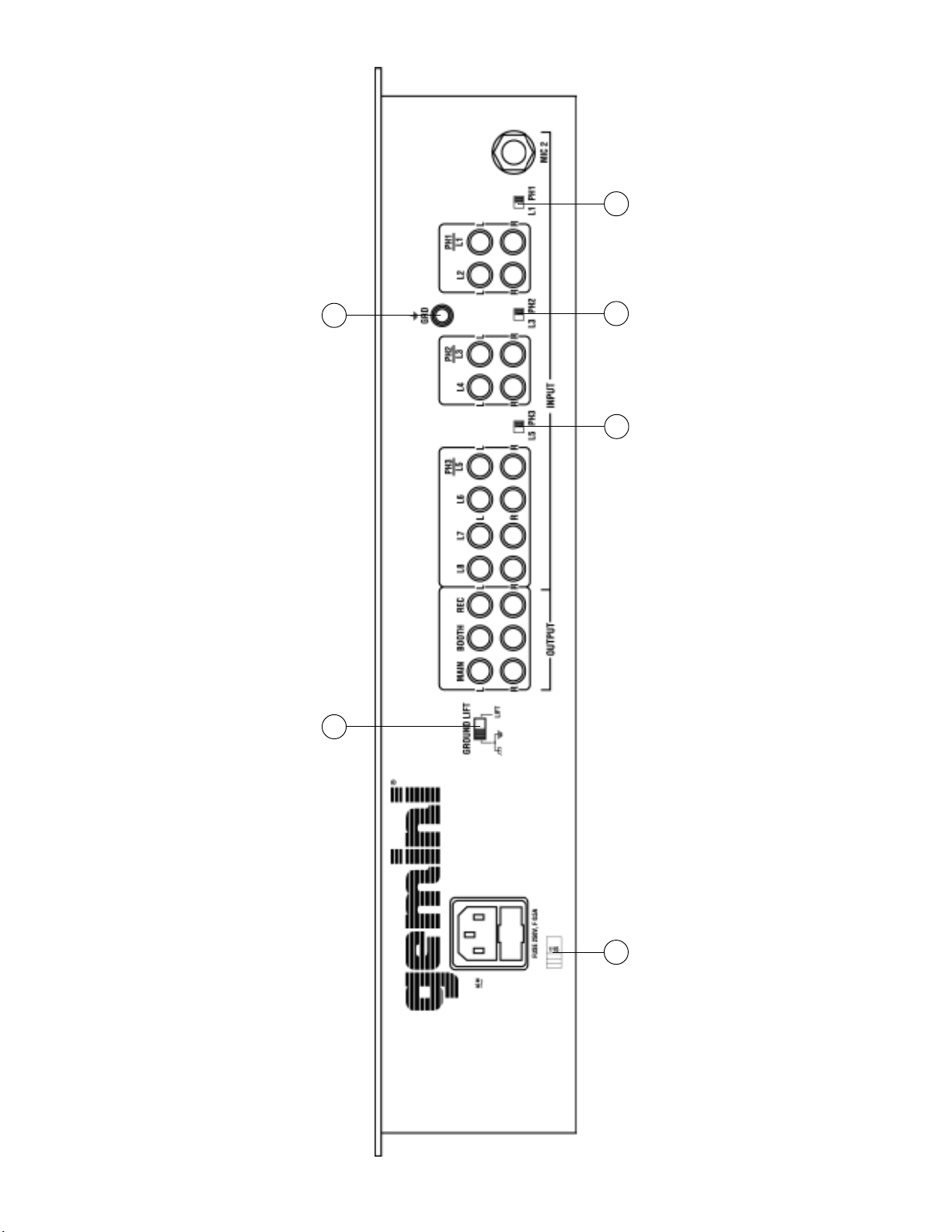
3. The PDM-16 is supplied with 3 sets of amp output jacks. The MAIN
OUTPUT (37) jacks are unbalanced and used to connect to your
main amplifier. The REC OUTPUT (39) jacks can be used to connect
the mixer to the record input of your recorder enabling you to record
your mix. The BOOTH OUTPUT (38) jacks allow you to hook up an
additional amplifier.
4. The MIC 1 (1) input (found on the front panel) accepts a 1/4" or XLR
connector. The MIC 2 (51) input (found on the rear panel) accepts
1/4" connectors. All accept balanced and unbalanced microphones.
5. On the rear panel are 3 stereo PHONO/LINE (43, 46, 49) inputs and
5 stereo LINE (40, 41, 42, 45, 48) inputs. The PHONO/LINE SWITCH
(44) enables you to set the (43) input to Phono or Line. The PHONO/
LINE SWITCH (47) enables you to set the (46) input to Phono or
Line. The PHONO/LINE SWITCH (50) enables you to set the (49)
input to Phono or Line. The phono inputs will accept only turntables
with a magnetic cartridge. A GROUND SCREW (52) for you to
ground your turntables is located on the rear panel. The stereo line
inputs will accept any line level input such as a CD player, a
cassette player, etc.
6. Headphones can be plugged into the front panel mounted
HEADPHONE (35) jack.
7. The PDM-16 comes with a front panel BNC LIGHT (28) jack. This
jack is for use with a gooseneck light like the Gemini GNL-700.
Using the Ground Lift Switch
Depending on your system configuration, sometimes applying the
ground will create a quieter signal path. Sometimes lifting the ground
can eliminate ground loops and hum to create a quieter signal path.
1. With the mixer on, listen to the system in idle mode (no signal
present) with the ground applied (the GROUND LIFT SWITCH (53)
in the left position).
2. Then turn the power off before moving the GROUND LIFT
SWITCH (53). Lift the ground by moving the GROUND LIFT SWITCH
to the right, turn the power back on and listen to determine which
position will provide a signal devoid of background noise and hum.
Keep the GROUND LIFT SWITCH in the ground position if the noise
level remains the same in either position.
CAUTION: DO NOT TERMINATE THE AC GROUND ON THE POWER
MIXER IN ANY WAY. TERMINATION OF THE AC GROUND CAN BE
HAZARDOUS.
Operation
1. POWER ON: Once you have made all the equipment connections to
your mixer, press the POWER SWITCH (29). The power will turn on
and the POWER LED (30) will glow RED.
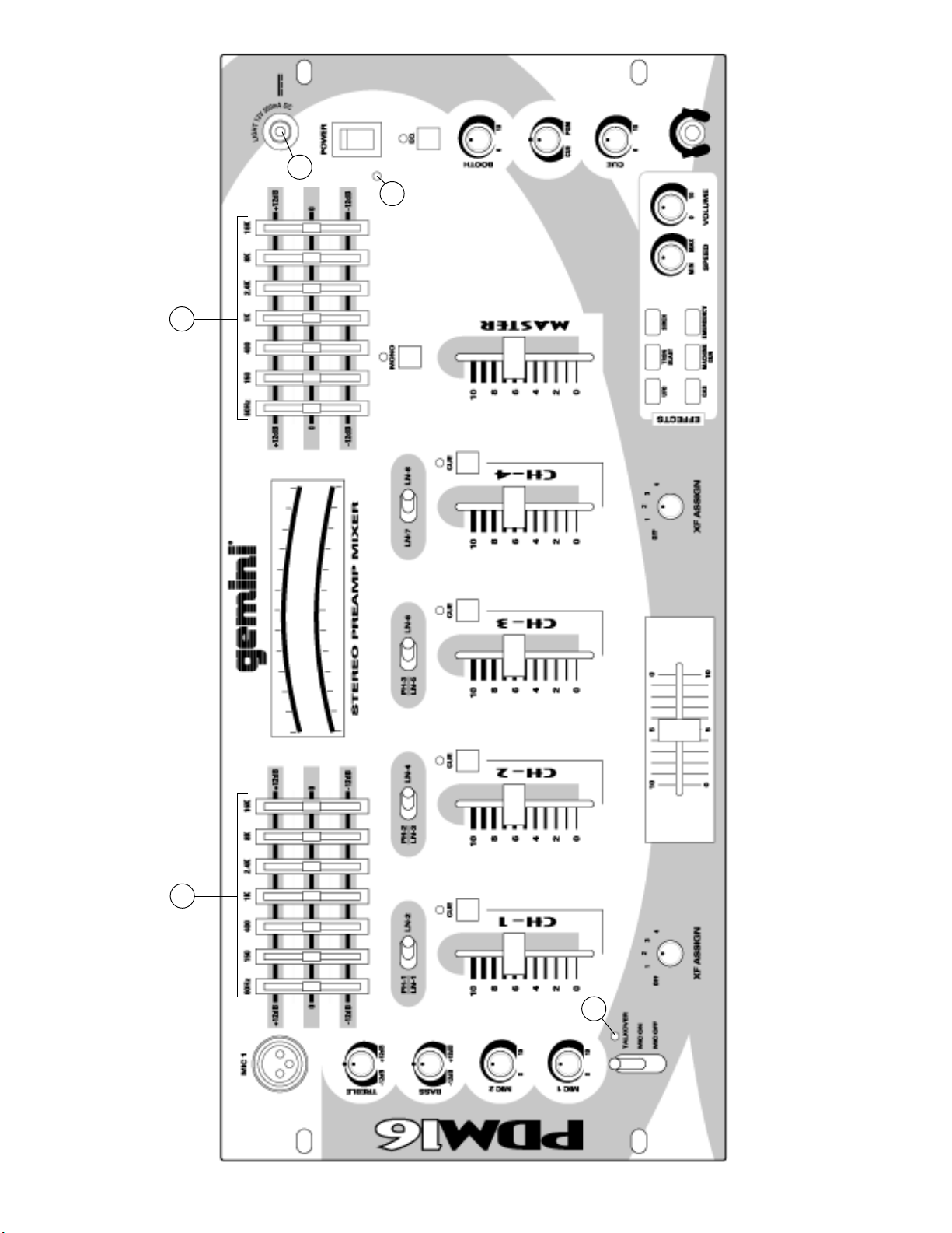
2. CHANNEL 1: Switch # (9) allows you to select the PHONO 1/LINE 1
(49) or the LINE 2 (48) input. The CHANNEL SLIDE (10) controls the
input level of this channel.
3. CHANNEL 2: Switch # (11) allows you to select the PHONO 2/LINE 3
(46) or the LINE 4 (45) input. The CHANNEL SLIDE (12) controls the
input level of this channel.
4. CHANNEL 3: Switch # (13) allows you to select the PHONO 3/LINE
5 (43) or the LINE 6 (42) input. The CHANNEL SLIDE (14) controls
the input level of this channel.
5. CHANNEL 4: Switch # (15) allows you to select the LINE 7 (41) or
the LINE 8 (40) input. The CHANNEL SLIDE (16) controls the input
level of this channel.
6. CROSSFADER SECTION: The CROSSFADER (18) allows the mixing
of one source into another. The PDM-16 features an assignable
crossfader. The ASSIGN (17, 19) switches allow you to select
which channel will play through each side of the crossfader. The
ASSIGN (17) switch has 5 settings (OFF, 1, 2, 3 or 4) and allows
you to select channel 1, 2, 3 or 4 to play through the left side of the
crossfader. The ASSIGN (19) switch has 5 settings (OFF, 1, 2, 3 or
4) and allows you to select channel 1, 2, 3 or 4 to play through the
right side of the crossfader. With the ASSIGN switch in the off
position, that side of the crossfader will be inactive. The
CROSSFADER (18) in your unit is removable and if the need arises
can be easily replaced. Crossfader units are available in three
varieties. Part # RF-45 (which is identical to the crossfader supplied
with the mixer) has a 45 mm travel from side to side. Part # RF-30 is
available with a 30 mm travel distance. Also available is the PSF-45
with a special curve designed for scratch mixing. Just purchase
one of these crossfader units from your Gemini dealer and follow
these instructions:
1. Unscrew the outside FADER PLATE SCREWS (B). Do not
touch the INSIDE SCREWS (C).
2. Carefully lift the fader and unplug the CABLE (D).
3. Plug the new fader into the cable and place it back in the
mixer.
4. Screw the fader to the mixer.
7. EQUALIZER SECTION: This unit features dual 7 band GRAPHIC
EQUALIZERS (8, 22) to allow you to adjust the sound for any room.
To activate the equalizer, press the EQ BUTTON (31) (the EQ LED
will light). By adjusting any of the 7 left equalizer slide controls (8),
you can cut or boost the tonal characteristics of the sound coming
from the left speaker by ±12 dB. By adjusting any of the 7 right
equalizer slide controls (22), you can cut or boost the tonal
characteristics of the sound coming from the right speaker by ±12
dB. Deactivate the equalizer by pressing the EQ BUTTON (31) again
(the EQ LED will turn off).
8. OUTPUT CONTROL SECTION: The level of the MAIN OUTPUT (37) is
controlled by the MASTER (24) slide. Activating the MONO (23)
button (the mono LED will light) makes the overall output mono. The
BOOTH (32) control adjusts the level of the BOOTH OUTPUT (38).
HINT: The BOOTH OUTPUT is used by some DJs to run monitor
speakers in their DJ Booth. You can also use it as a second ZONE
or AMP output.
NOTENOTE
NOTENOTE
NOTE: The REC OUTPUT (39)REC OUTPUT (39)
REC OUTPUT (39)REC OUTPUT (39)
REC OUTPUT (39) has no level control.
The level is set by the channel slides of the selected
channel. The tonal qualities can be controlled by the
equalizers.
9. TALKOVER SECTION: The purpose of the talkover section is to allow
the program playing to be muted so that the mic can be heard above
the music. The MIC/TALKOVER SWITCH (7) controls MIC 1 and MIC
2 and has three settings. When the MIC/TALKOVER SWITCH (7) is

Page 5
in the bottom position, MIC 1 and MIC 2 and talkover are off. When
the MIC/TALKOVER SWITCH (7) is in the center position MIC 1 and
MIC 2 are on, the MIC INDICATOR (6) will glow, but talkover is off.
When the MIC/TALKOVER SWITCH (7) is in the top position, MIC 1
and MIC 2 and talkover will be on and the volume of all sources
except the Mic inputs are lowered by 16 dB. The TREBLE (2) and
BASS (3) controls allow you to fully adjust the tone of MIC 1 and MIC
2. MIC 1 LEVEL (5) controls the level of MIC 1. The MIC 2 LEVEL
(4) controls the level of MIC 2.
10. CUE SECTION: By connecting a set of headphones to the
HEADPHONE (35) jack, you can monitor any or all of the channels.
Press the CUE ASSIGN (20) buttons for channels 1 - 4 to select the
channel or channels to be monitored and their respective LED
indicators will glow. Use the CUE LEVEL (34) control to adjust the
cue volume without effecting the overall mix. By moving the CUE
PGM PAN (33) control to the left you will be able to monitor the
assigned cue signal. Moving the control to the right will monitor the
PGM (program) output. Moving to the right will monitor the PGM
(program) output.
11. DISPLAY: The DISPLAY (21) indicates the MASTER output left and
right levels.
12. SOUND EFFECTS SECTION: Six different sound effects (UFO, TRON
BLAST, SIREN, GAS, MACHINE GUN and EMERGENCY) may be
added to your mix by depressing the SOUND EFFECTS CONTROL
BUTTONS (25). The volume of the effects can be adjusted using the
EFFECTS LEVEL CONTROL (27). The pitch of the effects can be
increased or decreased using the EFFECTS SPEED CONTROL (26).
Specifications
INPUTS:
DJ Mic....................................................1.5mV 2Kohm balanced
Phono.........................................................................3mV 47Kohm
Line.......................................................................150 mV 27Kohm
OUTPUTS:
Amp/Booth......................................................0 dB 1V 400ohm
Max..............................20V Peak to Peak
Rec...........................................................................225mV 5Kohm
MIC 1 & MIC 2:
DJ Mic....................................................1.5mV 2Kohm balanced
Bass......................................................................................± 12dB
High.......................................................................................± 12dB
GENERAL:
Frequency Response....................................20Hz - 20KHz +/- 2dB
Distortion................................................................................0.02%
S/N Ratio...............................................................better than 80dB
Talkover Attenuation..............................................................-16dB
Headphone Impedance.........................................................16ohm
Power Source.............................................115/230V 50/60Hz 10W
Dimensions................................................19”w x 4”h x 9”d
Weight........................................................................10.17 lbs
Description Part #
Cabinet Parts and Packing
1
2
4
5
6
7
8
9
10
11
12
13
14
15
16
17
18
19
20
21
22
23
24
25
26
27
28
29
30
31
32
33
34
35
36
37
38
39
40
41
42
43
44
Item #
Parts Lists
002-210
034-001
032-018
021-763
022-322
022-305
049-199
023-674
002-531
002-532
002-704
002-715
003-102
003-110
148-236
148-239
003-994
003-970
003-373
003-969
003-986
003-975
003-564
047-474
049-206
159-201
156-216
159-171
159-196
146-710
102-007
101-008
102-025
107-015
110-172A
111-043A
111-044A
111-046A
111-049A
111-050
111-051A
111-053A
131-081
PANEL CONTROL
PANEL REAR
COVER BOTTOM
BRACKET VR
HOLDER X-FADER
PROTECTOR PLATE FOR 115/230V SWITCH
SOUND CONTROL KEY
SWING LEVEL
KNOB PUSH (SMALL)
BUSHING FOR KNOB (SMALL)
KNOB SLIDE (BIG)
KNOB SLIDE
KNOB ROTARY (ASSIGN)
KNOB ROTARY (B)
KNOB INLAY (BLACK)
KNOB INLAY (GRAY)
EQ VR INLAY
TRIM VR
INLAY PLATE
HOLDER LED 3f LED(17mm)
HOLDER LED
HOLDER LED
WASHER XLR
PCB SPACER SUPPORT
PAD FOOT
BNC DUST PROOF CLOTH
DUST PROOF CLOTH (KNOB-SWING)
DUST PROOF CLOTH (VR)
FADER DUST PROOF CLOTH
GND SCREW
PAN-HEAD MACHINE SCREW; PMS 2X4(B)
FLAT-HEAD MACHINE SCREW; FMS 2X4 (Y)
PAN-HEAD MACHINE SCREW; PMS 2.6X4(B)
BAND-HEAD MACHINE SCREW; BMS 3X2X4
BAND-HEAD TAPPING SCREW/TWIN SCREW;
BTS-2 3X8(AB) TWIN
FLAT-HEAD TAPPING SCREW; FTS-3 3X6(AB)
BAND-HEAD TAPPING SCREW; BTS-3 3X10(AB)
BAND-HEAD TAPPING SCREW; BTS-3 3X6(AB)
FLAT-HEAD TAPPING SCREW; FTS-3 3X12(AB)
FLAT-HEAD TAPPING SCREW; FTS-3 3X12(Y)
BAND-HEAD TAPPING SCREW; BTS-3 3X5(AB)
BAND-HEAD TAPPING SCREW/TW-E;
BTS-3/TW-E 3X6(AB)
NUT/WASHER 3mm
262-044
262-045
262-047
262-046
262-048
262-049
PRINTED CIRCUIT BOARD PDM-24S-1:
IN/OUT
PRINTED CIRCUIT BOARD PDM-24S-2:
MAIN
PRINTED CIRCUIT BOARD PDM-18-3:
EFFECT
PRINTED CIRCUIT BOARD PDM-24S-4:
FADER
PRINTED CIRCUIT BOARD PDM-18-5:
PHONES
PRINTED CIRCUIT BOARD PDM-18-6
Description Part #
Printed Circuit Boards
Item #
1
2
3
4
5
6

Page 6
Parts Lists - PCB1 Input/Output
079-027
079-003
081-027
092-078
161-105
161-106
RECTIFIER DIODE 1N4002 (1N4003,1N4004)
SILICON DIODE 1N4148
SLIDE SWITCH 2P2C PH/LINE
PHONE JACK 6.3
4P RCA JACK P=14mm
6P RCA JACK P=14mm
D3-8, D507, D508
D1, D2
SW1-3
J1
J2-5
J6
Designators Description Part #
Electrical Parts
Item #
1
2
3
4
5
6
076-095
076-104
TRANSISTOR 2SC2878
TRANSISTOR 2SA1048 (2SA1317)
Q2-5
Q1
Designators Description Part #
Transistors
Item #
1
2
074-145
074-107
074-114
INTEGRATED CIRCUIT NJM2068LD
INTEGRATED CIRCUIT NJM7812FA
INTEGRATED CIRCUIT NJM7912FA
IC1-4
IC6
IC7
Designators Description Part #
ICs
Item #
1
2
3
Parts Lists - PCB2 Main
082-019
082-028
083-069
083-097
072-035
072-107
072-081
071-101
071-159
080-091
080-079
080-080
080-078
LEVER SW 4P2C P=18 PH/LN,LN/LN
ROTARY SWITCH 1-2-5 L=17 FAD ASSIGN
PUSH SWITCH 2P2C L=12.5 CUE,MONO
SWITCH 4P2C L=12.5
SLIDE VR 45mm L=20 CH VOL MASTER 50KA×2
SLIDE VR 30mm L=15 EQ 20KW C.C
SLIDE VR 45mm L=20 FADER 100KB×2
ROTARY VR 16f L=20 TREBLE,BASS 10KB C.C
ROTARY VR 16f L=20 MIC LEVEL 10KA
LIGHT EMITTING DIODE (RED)
LIGHT EMITTING DIODE (GREEN)
LIGHT EMITTING DIODE (YELLOW)
LIGHT EMITTING DIODE (RED)
SW4-7
SW9-10
SW12-15
SW8
VR1-4
VR7-13
A1
VR14-15
VR5-6
Red 3.15
Green 2.5x6.5
Yellow 2.5x6.5
Red 2.5x6.5
Designators Description Part #
Electrical Parts
Item #
1
2
3
4
5
6
7
8
9
10
11
12
13
074-104
074-145
074-115
074-022
INTEGRATED CIRCUIT
NJM4558LD(M5218AL,BA4558N)
INTEGRATED CIRCUIT NJM2068LD
INTEGRATED CIRCUIT M5229P
INTEGRATED CIRCUIT LB1403N
IC11
IC8-10
IC12
IC13-16
Designators Description Part #
ICs
Item #
1
2
3
4

Page 7
Parts Lists - PCB3 Phono
080-091
ZENER DIODE 3.6V 1/2W
LIGHT EMITTING DIODE (RED) 3.15f
D37
D10, D36, D40
Designators Description Part #
Diodes
Item #
1
2
092-078
083-069
083-097
072-035
072-107
071-084
071-066
071-161
071-178
071-176
PHONE JACK 6.3f
PUSH SWITCH 2P2C L=12.5 CUE,MONO
PUSH SWITCH 4P2C L=12.5 EQ
SLIDE VR 45mm L=20 CH VOL MASTER 50KA×2
SLIDE VR 30mm L=15 EQ 20KW C.C
ROTARY VR 16f L=20 CUE LEVEL 50KA×2
ROTARY VR 16f L=20 VOLUME 50KA
ROTARY VR 16f L=20 BOOTH 10KA×2
ROTARY VR 16f L=20 CUE PGM 20KW×2
ROTARY VR 16f L=20 SPEED 250KB×2CC
J10
SW20
SW22
VR30
VR20-26
VR17
VR16
VR31
VR32
VR27
Designators Description Part #
Electrical Parts
Item #
1
2
3
4
5
6
7
8
9
10
074-104
074-113
074-145
074-115
074-141
074-140
INTEGRATED CIRCUIT
NJM4558LD(M5218AL,BA4558N)
INTEGRATED CIRCUIT NJM4556L
INTEGRATED CIRCUIT NJM2068LD
INTEGRATED CIRCUIT M5229P
INTEGRATED CIRCUIT VM8080
INTEGRATED CIRCUIT GEMNI-01
IC18-20
IC26
IC25
IC17
IC21
IC22
Designators Description Part #
ICs
Item #
1
2
3
4
5
6


+12
-12
X30
+12
-12
+12
-12
ML
RL
RR
BL
BR
ML
MR
X31
X29
X32
+12
R246
12K R225
10 R226
10
IC25A
2068LD
C219 101
C157
10/16
C173
22/16 C174
22/16
+12
C158
100/16
C159
100/16
IC25B
2068LD
C220 101
R247
12K
C160
10/16
R252
4K7
R253
4K7
R254
10K
R255
10K
R212
10K
R213
10K
R256
7K5
R257
7K5
R201
4K7
D10
LED
+12
-12
R193
1K
R194
1K
R203
4K7
D36
LED
-12
VR30A
50KA
VR30B
50KA
IC19A
4558
IC19B
4558
R185
100K
R186
100K
R258
6K8
R218
1K3
R259
6K8
R219
1K3
C161
10/16
C162
10/16
C175
22/16 C176
22/16
C183
47
C184
47
R227
10 R228
10
+12
-12
VR31A
10KA
VR31B
10KA
IC20A
4558
IC20B
4558
R187
47K
R189
47K
R204
4K7
R195
1K
R205
4K7
R196
1K
C163
10/16
C164
10/16
C177
22/16 C178
22/16
C185
47
C18647
R229
10 R230
10
+12
-12
SW20A
SW02
SW20B
SW02
SW22A
SW04
SW22B
SW04
SW22C
SW04
RL RR
MR
BR
BL
MR MR
ML ML
RL
RR
D40
LED
R199
4K7
+12
R207
36K
R208
10K
R209
10K
R210
36K
R121
100K
R130
100K
C189
332
C208
222
C190
153
C210
47
R131
100K
R132
100K
R240
180K
R179
100K
R211
18K
IC18A
4558
IC18B
4558
C202
1/16 C215
100/16
C91
47/16
BIAS
1IN
2PREO
3OUT
4SEL
5OSC1
6OSC2
7OSC3
8OSC4
9VSS
10 A6
11 A7
12
VDD 24
CASB 23
A8 22
DATA 21
WRB 20
RASB 19
A0 18
A1 17
A2 16
A3 15
A4 14
A5 13
IC23
HT8955
C182
681
C216 123
C209
472
R180
100K
R181
100K
R102
47
R107
47
C211
331
C155
10/16
C120
47/16
+12
-12
VR18
10KB
VR19
10KB
VR29
500KB
R244
180K
R245
330/0.5
R224
10
R235 8K2
A0
5A1
7A2
6A3
12 A4
11 A5
10 A6
13 A7
9A8
1
RAS
4CAS
15 WE
3
Q14
D2
VCC 8
GND
16
IC24
41256
D38
5V C217
104
C156
10/16
+12
R202
4K7
D35
LED
-12
R184
100K
SW21A
SW02
SW21B
SW02
R217
100K
X27
13
12
11
109
8
7
6
2
KEY1
KEY2
KEY3
KEY4
KEY5
KEY6
KEY7
KEY8
VDD
317
18
16
14
154
5
1VSS
NC1 NC2
NC3
LH
OSC1
OSC2
OUT
OUT
IC21
VM8080
2
3
4
5
6
7
8
9
10
1
12
13
14
15
16
17
18
19
20
11
OSC1
OSC2TG1
TG2
TG3
TG4
TG5 TG6
TG7
TG8
VSS VDD
AUD
IND1
IND2
IC22
HT-82200
R190
1K
R191
1K
R236
47K
R237
10K
R238
300K
R239
47K
R192
3K3
VR27A
250KB
VR27B
250KB
C200
1/16
C201
1/16
D37
3.6V C206
153
C207
4.7/16
+5
R197
1K
-VCC 20
GND 19
+VCC 18
OUT 17
N INP 16
P INP 15
NF7 14
IN7 13
NF6 12
IN6 11
NF1
2
IN1
1
IN2
3
NF2
4
IN3
5
NF3
6
IN4
7
NF4
8
IN5
9
NF5
10
IC17
M5229P
R222
10 R223
10
R233
3K3
R234
3K3
C187
471
C195
124 C198
393 C194
123 C193
682 C192
272 C191
821
C203
124 C196
563 C197
183
C179
822
C188
471
C171
22/16
C172
22/16
C153
10/16
C204
2.2/16 C199
1/16 C205
0,47/16
C154
10/16
-12
+12
R216
10K
VR20
20KW VR21
20KW VR22
20KW VR23
20KW VR24
20KW VR25
20KW
VR26
20KW
VR32A
20KW
VR32B
20KW
R214
10K
R242
33K
R215
10K
R243 33K
R248
18K
R249
18K
R250
18K
R251
18K
VR17A
50KA
VR17B
50KA
IC26A
4556
IC26B
4556
R182
100K
R183
100K
R220
1K
R260
68K
R221
1K
C165
10/16
C166
10/16
C180
470/16 C181
470/16
C221 39
C222
39
R231
10 R232
10
+12C167
10/16
C168
10/16
R108
47
R120
47
C213
222
C214
222
X26
R261
68K
1
2
X28
C169
10/16
C170
10/16
-12
C218
104
R133
1K
VR16
50KA
C212
682
X44
MONO
MASTER
BOOTH
EQUALIZER
ECHO
LEVELREPEAT
DELAY
LEVEL
SPEED
CUE\PGM
CUE LEVEL
SW23
SW-PBSW24
SW-PBSW25
SW-PBSW26
SW-PBSW27
SW-PBSW28
SW-PB
1
2
3J10
PHONEJACK2
1
2
3
X34
IC1A
2068LD
IC1B
2068LD
R7
47
R1
1K 1%
R3
1K 1% R4
30K 1%
R5
47
R9
30K 1%
R2
30K 1%C1
101
C11
101
C7
101
C5
101
C6
47/16
C3
10/16 C2
22/16
C4
10/16
C8
47/16
X1
C10
10/16
C9
10/16
C12
22/16
R10
1K 1%
R8
1K 1%
R6
30K 1%
J1
-12
+12
+12
-12
2
31
4 8
IC2A
2068LD
IC2B2068LD
R22
100K R19
47 R12
47
R20
8K2
R23 180
R18
47K
R17
8K2
R13
47K
R11
180 R15
100K
C24
822
C22
101
C26
273
C15
101
C16
273
C20
822
C21
47/16
C13
47/16
C14
47/16
C18
47/16
C23
10/16
C17
10/16
R21
1K
R16
1K
R26
1K8
R25
1K8
C28
101
C29
101
C25
10/16
C30
10/16
C19
10/16
C27
10/16
+12
-12
IC3A
2068LD
IC3B2068LD
R38
100K R35
47 R28
47
R36
8K2
R39 180
R34
47K
R33
8K2
R29
47K
R27
180 R31
100K
C41
822
C42
101
C44
273
C33
101
C34
273
C38
822
C39
47/16
C31
47/16
C32
47/16
C35
47/16
C4010/16
C36
10/16
R37
1K
R32
1L
R42
1K8
R41
1K8
C46
101
C47
101
C43
10/16
C48
10/16
C37
10/16
C45
10/16
+12
-12
IC4A
2068LD
IC4B2068LD
R53
100K R51
47 R44
47
R52
8K2
R55 180
R50
47K
R49
8K2
R45
47K
R43
180 R47
100K
C60
822
C58
101
C62
273
C51
101
C53
273
C56
822
C57
47/16
C49
47/16
C50
47/16
C54
47/16
C5910/16
C52
10/16
R54
1K
R48
1K
R58
1K8
R57
1K8
C64
101
C65
101
C61
10/16
C66
10/16
C55
10/16
C63
10/16
R24
1K8
R14
1K8
R30
1K8
R40
1K8
R56
1K8
R46
1K8
X2
X3
X4
X5
X6
R60
1K8
R59
1K8
C69
101
C68
101
C70
10/16
C67
10/16
R62
1K8
R61
1K8
C72
101
C73
101
C74
10/16
C71
10/16
R78
180
R81
47K
R79
330
R77 5K1
R84
180
R80
330
R83
5K1
C82
22/16
C81
22/16
R82
47K
Q4 2SC2878
Q5 2SC2878
R70
180
R72
47K
R71 330
R69 5K1
R76
180
R73
330
R75
5K1
C80
22/16
C79
22/16
R74
47K
Q2 2SC2878
Q3
2SC2878
R65
47K
R67
47K
R63
8K2
R68
8K2
C76
10/16
C77
10/16
D3
1N4002 D5
1N4002
D6
1N4002
D4
1N4002 C89
470/25
C90
470/25
C87
103
C88
103
C84
4,7/16
C85
4,7/16
-12
-12
+12
Vin
1
GND
2
+12V 3
IC6 7812
Vin
2
GND 1
-12V 3
IC7
7912
Q1
2SA1317
R66
560K
D2
1N4148
D1
1N4148
C75
220/16
C78
4,7/16
+12
SW1A
SW1B
SW2A
SW2B
SW3A
SW3B
J2A
J2B
J3A
J3B
J4A
J4B
J5A
J5B
J6A
J6B
J6C
R64
1K 1
2
X12
D8
1N4002
D7
1N4002
C86
470/16
X7
X?
D507
1N4002 D508
1N4002
1
2
3
4
5
X11
1
2
3
4
X8
R85
2M2
-12
MIC-2
PH1; L1
PH1/L1
L2
PH-2; L3
L4
PH-2/L3
PH-3/L5
PH-3; L5
L6
L7
L8
OUT REC.
OUT BOOTH
OUT AMP.
+12
1
2
3
X14
X15
11 12
10
SW4D
23
1
SW4A
56
4
SW4B
89
7
SW4C
R85
47K
R101
4K7
R86
47K
R87
47K
D9
LED
+12
VR1A
50KA
VR1B
50KA
R88
47K
VR5
10KA
R110
10K
R134
27K R135
22
R139
1K3
R136
22
R140
1K3 R109
1K8
R141
1K
R111
10K IC8A
2068LD
IC8B
2068LD
C92 47
C95
224
C97
223
C96
224
C98
223
C99
221
C100
10/16
C114
47/16 C115
47/16
C101 47/16
-12 +12
R112
10K
R113
10K
R142
47K
R143
47K
R144
47K
R145
47K
R146
47K
R147
47K
R148
47K
R149
47K
-VCC 20
GND 19
+VCC 18
OUT 17
N INP 16
P INP 15
NF7 14
IN7 13
NF6 12
IN6 11
NF1
2
IN1
1
IN2
3
NF2
4
IN3
5
NF3
6
IN4
7
NF4
8
IN5
9
NF5
10
IC12
M5229P
R150
10
R151
10 R155
3K3
R156
3K3
C125
471 C127
821 C128
272 C129
682 C130
123 C131
124
C126
124
C139
563
C138
183
C137
822
C135
393
C116
22/16
C102
10/16
C134
1/16
C133
2.2/16
C132
0.47/16
C103
10/16
-12+12
R157
100K
R137
10
R138
10
IC9A
2068LD
C140 101
C144
22/16
C117
22/16 C118
22/16
-12 +12
R159
20K
C104
47/16
C105
47/16
R160
20K
IC9B
2068LD C141
101
R158
100K
SW8A
SW8B
SW8C
C145
22/16
C146
22/16
SW9A
SW9B
SW10B
SW10A
R114
10K
R115
10K
C119
22/16
1
9
2
6
3
4
7
8
5
IC13
LB1403N
1
9
2
6
3
4
7
8
5
IC14
LB1403N
1
9
2
6
3
4
7
8
5
IC15
LB1403N
1
9
2
6
3
4
7
8
5
IC16
LB1403N
D11
LED
D12
LED
D13
LED
D14
LED
D15
LED
D16
LED
D17
LED
D18
LED
D19
LED
D20
LED
D21
LED
D22
LED
D23
LED
D24
LED
D25
LED
D26
LED
D27
LED
D28
LED
D29
LED
D30
LED
R116
10K R161
100K
R165
120K R167
160K
R117
10K R169
8K2
R118
10K R162
100K
R166
120K R168
160K
R119
10K R170
8K2
R172
47
R173
47
R174
47
C106
10/16
C107
4.7/16
C108
10/16
C109
10/16
C110
4.7/16
C111
10/16
R152
47
R175
47K
R153
10
R154
10
IC10A
2068LD
C142 47 C147
22/16
C121
22/16 C122
22/16
-12 +12
C148
100/16
C149
100/16
IC10B
2068LD
C143 47
R176
47K
C150
22/16
SW8D
+12
-12
+12
-12
R122
10K
VR7
20KW VR8
20KW VR9
20KW VR10
20KW VR11
20KW VR12
20KW
VR14
10KB
VR15
10KB
VR13
20KW
C136
471
SW12A
SW12B
X16
11 12
10
SW5D
23
1
SW5A
56
4
SW5B
89
7
SW5C
R89
47K
R103
4K7
R90
47K
R91
47K
D31
LED
+12
VR2A
50KA
VR2B
50KA
R92
47K
R123
10K
R124
10K
SW13A
SW13B
X17
11 12
10
SW6D
23
1
SW6A
56
4
SW6B
89
7
SW6C
R93
47K
R104
4K7
R94
47K
R95
47K
D32
LED
+12
VR3A
50KA
VR3B
50KA
R96
47K
R125
10K
R126
10K
SW14A
SW14B
X18
11 12
10
SW7D
23
1
SW7A
56
4
SW7B
89
7
SW7C
R97
47K
R105
4K7
R98
47K
R99
47K
D33
LED
+12
VR4A
50KA
VR4B
50KA
R100
47K
R127
10K
R128
10K
SW15A
SW15B
R106
4K7
D34
LED
+12
R129
10K
IC11A
4558
IC11B
4558
R177
27K R163
47K
R164
47K
R178
27K
C151
22/16
C152
22/16
C112
10/16
C113
10/16
C93
47
C94
47
C123
22/16
R188
47
C124
22/16
+12
1L
1R
2L
2R
3L
3R
4L
4R
4R
3R
2R
1R
4L
3L
2L
1L
4R
3R
2R
1R
1L
2L
3L
4L
+V IND GND
+V INDGND
VR6
10KA
R171
47
+12
1
2
3
X19
1
2
3
X24
X23
+12 -12
X20
X22
QUE
QUE
QUE
QUE
CH-1
CH-2
CH-3
CH-4
MIC-1
MIC-2
X-FAD. ASSIGN
X-FAD. ASSIGN
A
B
T.O
ON
OFF
T.O.
1
2
X21
T1
TR05
1
2
X28
SW18
FSW19
SW-SPST
C141
103
J7
PLUG
J8
PLUG
J9
LAMP
AC 220/110 V
SW
X27
R87B 100KB
R87A
100KB
CROSS FADER
X30
PLUG06
059-166
Schematic
Table of contents
Other Gemini Music Mixer manuals

Gemini
Gemini CDM-3600 User manual

Gemini
Gemini MX-01 User manual

Gemini
Gemini CDM-3200 User manual

Gemini
Gemini EX-26 User manual

Gemini
Gemini PS-828X User manual

Gemini
Gemini FX-7000 User manual

Gemini
Gemini PDM-24s User manual

Gemini
Gemini PMX-20 User manual

Gemini
Gemini PS-424x User manual

Gemini
Gemini PMX-01 User manual

Gemini
Gemini pmx-7 User manual

Gemini
Gemini PS-626USB Reference manual

Gemini
Gemini PS-626i User manual

Gemini
Gemini PS-626EFX User manual

Gemini
Gemini BPM-500 User manual

Gemini
Gemini PMX-20 User manual

Gemini
Gemini PDM-3004 User manual

Gemini
Gemini MM-1000 Mixer User manual

Gemini
Gemini EX-26 User manual

Gemini
Gemini PDM-10 User manual