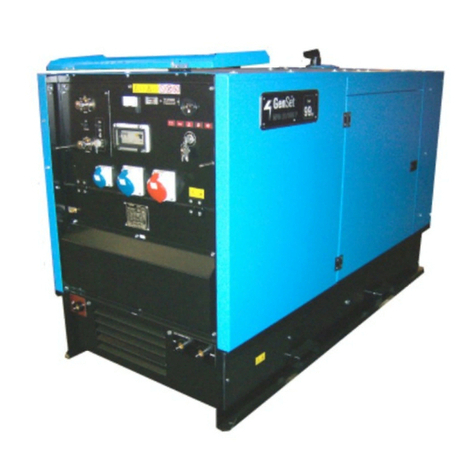
Gen Set MPM 6/230 S-L User manual

MPM 6/230 S-L
MANUALNUMBER
MI-M-00006200
MOTORWELDINGSET/ GENERATINGSET
FORSTATIONARYUSE
USEANDMAINTENANCEMANUAL
GB
REVISIONLEVEL00
25-01-2016
GENSETS.p.a.
ViaStazione,5- 27030VillanovaD’Ardenghi (Pavia)Italy
Tel. (+39) 0382-5091 - Fax (+39) 0382-509-244
E-mail:[email protected]-internet://www.genset.it

Machinespecificationscanbemodifiedatanytimewithout anyobligationtoupdatethis
publication.It isrecommended toreadthismanualthoroughlybecauseincorrect
operationmay resultinthewarrantybeingvoid.Therefore itis alsorecommended touse
onlyoriginalGenSetS.p.a. spareparts.
Reproductionof thismanual isnotpermitted,unless writtenapprovalisobtainedfrom
Gen Set S.p.a.

3
MPM6/230S-L
MI-M-00006200
GB
TABLEOFCONTENTS
01. REFERENCE GUIDE ..................................................................................................page.4
02.ACCIDENTPREVENTION / SAFETYREGULATIONS..........................................page.7
03. ENVIRONMENTALDIRECTIONS .........................................................................page.14
04. THE MACHINE ...........................................................................................................page.16
05.TECHNICALDATA....................................................................................................page.20
06. INSTALLINGAND STARTINGTHE MACHINE ..................................................page.25
07. USING THE MACHINE ............................................................................................page.29
08. MOVING THE MACHINE ........................................................................................page.33
09. MACHINE MAINTENANCE ..................................................................................page.36
OIL
11. SPARE PARTS ............................................................................................................page.44
12. ELECTRICAL DIAGRAM ........................................................................................page.52
10.OPTIONAL ACCESSORIES ......................................................................................page.41
13.ATTACHMENTS ........................................................................................................page.54

4
GB 01.REFERENCEGUIDE
MPM6/230S-L
MI-M-00006200
01.1- This publication.....................................................................................................................page 5
01.2- Purpose................................................................................................................................page 5
01.3- Reference to regulations........................................................................................................page 5
01.4- Using this manual..................................................................................................................page 6
01.5- Terminology..........................................................................................................................page 6
01.6- Abbreviations........................................................................................................................page 6

5
GB
01.REFERENCEGUIDE
MPM6/230S-L
MI-M-00006200
01.1THIS PUBLICATION
The “USEAND MAINTENANCE MANUAL”, published
by the manufacturer, is an integral part of the power
generator.Themanualis identifiedby apublication identifier,
printed on the cover page and repeated at the foot of every
page, which allows the reader to identify and locate the
publication and/or make subsequent reference to it.
All the information included herein is brought up to the date
ofpublishing. Themanufacturer reserves theright tomodify
it without notice, and accepts no responsibility for any error
and/or omission.
01.2PURPOSE
The USE AND MAINTENANCE MANUAL is intended
for users and holds all the information necessary for using
the product and perform its regular maintenance. Good
working conditions, long life of the power generator, and
the protection and safety of users, will be dependent upon
strictobservance ofthe instructions included inthis manual.
It is advisable to read thoroughly and observe the directions
included in this publication, which are organised, as far as
possible, according to the chronological sequence of
operations when approaching the unit.
01.3REFERENCETOREGULATIONS
Thismanual hasbeen producedaccording tothe regulations
providedby:
– Attachment “I” to 2006/42/EC Directive
– UNI EN 292/2 - 1992, article 5.5.
This generator is complying with the provisions of the
followingdirectives:
– 2006/42/EC: Machine Directive;
– 2006/108/EC: Electromagnetic Compatibility Directive;
– 2006/95/EC: Low Voltage Directive;
–2000/14/EC:Noise Emissionin theEnvironment Directive.
SOME NOTES ABOUT NOISE EMISSION
(2000/14/EC Directive)
Sound power level (LWA):
Indicates the level of noise as required by the European
Directive. It represents the amount of sound energy emitted
in the time unit and is a characteristic of the sound source
independent of the distance from the point of measurement.
dB(A) is the unit of measurement.
Sound pressure (Lp):
Measurement of the pressure generated by the emission of
sound waves taken at a certain distance from the source.
Its value changes with the distance from the source and is
also measured in dB(A).
WARNING! Special attention must be paid to avoiding
confusion between LWA and Lp. In this manual the noise
emission is indicated as sound power level (LWA) and sound
pressure (Lp) as well. Sound pressure values (Lp), as a
function of distance, can be calculated for equipment with
a given sound power level (LWA) using the following table:
Lp at 1 m = LWA -8 dB
Lp at 4 m = LWA -20 dB
Lp at 7 m = LWA -25 dB
Lp at 10 m = LWA -28 dB
Lp at 16 m = LWA -32 dB
Example: for equipment with LWA =90 dB:
Lp at 1 m = 90 dB - 8 dB = 82 dB
Lp at 4 m = 90 dB - 20 dB = 70 dB
Lp at 7 m = 90 dB - 25 dB = 65 dB
Lp at 10 m = 90 dB - 28 dB = 62 dB
Lp at 16 m = 90 dB - 32 dB = 58 dB
The Directive 2000/14/EC specifies that the limits of sound
emissions are dependent on the power output of power
generators or welding generators. The limits set down by
this Directive are relating to the sound power level
guaranteed and not to the sound power level measured,
which does not take account of all the possible variables
resulting from either the production stage or the different
measurement procedures.
The reduction of the limits provided for has been divided in
two phases: the first phase in force from 03/01/02 and the
second phase in force from 03/01/06. The following table
shows the sound power levels (LWA) approved for power
generators and welding generators.
TheDirective 2000/14/ECrequires that thepower generator
or welding generator is marked with the sound power level
guaranteed and the CE Marking relating to the EC
Declaration of Conformity.
The marking of the sound power level
guaranteed consists of a number in dB,
the LWA mark and the specific symbol:
Electric
power output
Pel kW
Sound power level
permitted
from 03/01/02 Phase 1
Pel
2 < Pel
Pel
LWAdB (A) 97 + log Pel
LWAdB (A) 98 + log Pel
LWAdB (A) 97 + log Pel
Sound power level
permitted
from 03/01/06 Phase 2
LWA dB (A) 95 + log Pel
LWA dB (A) 96 + log Pel
LWA dB (A) 95 + log Pel

6
GB 01.REFERENCEGUIDE
MPM6/230S-L
MI-M-00006200
01.6 ABBREVIATIONS
01.4 USINGTHIS MANUAL
“Symbols” are used along with text to highlight and point
out visually the relevance of different types of information.
Graphic representation of symbols and their meaning:
Points out to important complementary information.
The non-observance of associated directions can cause
damage, even irreparable, to the power generator.
Points out to possible situations dangerous for people.
This manual, together with appendices and any inclusions,
must be kept with the utmost care and always be
unabridged, undamaged and readable in its entirety.
If lost, a copy must be promptly requested to the
manufacturer.
WELDING PROCESS: LEGEND
Shieldedmetal arcwelding (SMAW).
Gastungsten arcwelding (GTAW)Lift Startonly.
Gasmetal arcwelding (GMAW).
01.5 TERMINOLOGY
Explanation of some of the terms relating to the power
generator and used in this publication.
FRONT:thepart of theunit wherethecontrolpanel islocated.
A ampere
V volt
ca alternate current
cc direct current
3F + N three phase plus neutral
Ah ampere / hour
Hz hertz
hp horsepower (1hp = 0,736 kW)
cos power factor
kW kilowatt
kWm kilowatt motor
kVA kilovolt ampere
kg kilogram
l litre
l/h litre / hour
mm millimetre
m metre
s second
°C degree Celsius
LWA sound power level
Lp sound pressure
dB(A) decibel
BACK: the opposite part.
RIGHT OR LEFT SIDE: referred to an operator standing in
front of the unit and looking at the control panel.

7
GB
02.ACCIDENTPREVENTION /SAFETYREGULATIONS
MPM6/230S-L
MI-M-00006200
02.1- Precautions to be observed...................................................................................................page 8
02.2- Risks for the operator when using this unit.............................................................................page 9
02.3- Protective clothing recommended for operators......................................................................page 9
02.4- Meaning of safety signs......................................................................................................page 10
02.5- Location of safety signs provided on the unit........................................................................page 13

8
GB 02.ACCIDENTPREVENTION /SAFETYREGULATIONS
MPM6/230S-L
MI-M-00006200
Read carefully the instructions for use; operate according
to the regulations in force in your country.
02.1SAFETYPRECAUTIONSTOBE
OBSERVED
WHENFUELLING
Engine fuel can cause fire or explosion:
• Stop the engine before fuelling and let the machine cool.
• Do not fuel while smoking or near sparks or flames.
• Do not overfill the tank. In case, clean up any spilled fuel
immediately before starting the engine.
WHENPERFORMINGMAINTENANCE
• Always switch off the generator before performing any
service.
• It is not advisable that maintenance operations are
performed by unskilled personnel.
•Alwaysusethe necessaryindividualprotection equipment.
• The battery contains sulphuric acid in solution, and can
cause explosion:
- Always disconnect the battery.
- Never short battery’s positive and negative
terminals, as this can cause battery explosion.
- Battery explosion can cause burns and blindness.
- Always wear protection gloves, face masks and
acid resistant cloth.
• In case of contact with acid do the following:
- In case of splash of acid into the eyes: wash
immediately with clean water and seek medical
advice as soon as possible.
- In case of splash of acid on the skin: wash
immediately with clean water and seek medical
advice as soon as possible.
- In case of ingestion of acid: seek medical advice
immediately.
• When checking the engine oil level or changing the oil:
- Beware: hot oil can cause burns. Always wear
protective gloves.
BEFORESTARTINGTHEGENERATOR
• Connect the power generator to earth using the proper
terminal and a cable of suitable size without interposing
switchesor other devicescapable ofbreaking theelectrical
connection. Make sure that no load is connected to the
machine.
WHENMOVINGTHEGENERATOR
• When transporting the generator to the place of use, it
must be firmly fastened to the vehicle.
• When moving and transporting the generator, do not tilt
excessively.
• Lift the generator using the lifting eye provided on the
top of the unit.
• If it is necessary to lift the generator using a forklift, the
position of forks in such a way as to balance the
generator weight correctly.
• When lifting and moving the generator, do not stay or
walk within the proximity of the lifting and moving
equipment.
• Never leave the generator slung overhead.
WHENUSINGTHEGENERATOR
• Check that the generator is properly connected to
earth.
• Check that your tools’ cables are in perfect conditions.
• Make sure that switches and controls are correctly set
for starting (see Chapter 07).
• Operate the generator in well-ventilated areas, making
sure that the exhaust is not restricted.
• Keep the generator away from walls or other
obstructions to avoid the hot air or exhaust recycling
that would cause generator overheating.
• Use fume extractors to ensure the correct air turnover
when operating indoors.
• Do not operate near flammable materials.
• Fill fuel tank when engine is stopped. Do not smoke when
fuelling.
• Do not overfill the tank and clean up any spilled fuel.

9
GB
02.ACCIDENTPREVENTION /SAFETYREGULATIONS
MPM6/230S-L
MI-M-00006200
•Check thelevel ofany liquidsthat may leakinto thebund..
Empty the bund if necessary. Do not dump the liquids onto
land but dispose of them according to the local legislation.
• Check daily that there are no leaks of liquids from the
engine.
Donotdisconnectthebatterycableswhenthepower
generatorisrunning.
USESNOTALLOWED
• Do not connect the power generator to the commercial
electrical grid.
• Do not operate near flammable materials or if explosive
gases or vapours are present.
• Do not operate in narrow or poorly ventilated places.
• Do not operate if the electrical protections are not
effective.
• Do not touch the silencer and the engine parts close to it.
• Do not perform service when the engine is running.
• Do not tamper with electrical components.
•Any service operation on electrical components must be
performed after stopping the engine and by skilled
personnel.
•Stay awayfrom movingparts anddo not getclose wearing
loose clothing, ties, necklaces, bracelets, and anything
that can be caught by moving parts.
02.2RISKSFORTHE OPERATORWHEN
USING THIS UNIT
ELECTRICSHOCK
Electric shock can injure or kill. This electric energy can
cause severe or fatal shock to the operator or others in the
workplace.
• Always connect the generator to earth.
• Never touch any parts that are electrically live.
• Repair or replace all worn or damaged parts.
• Install and maintain equipment according to regulations.
• Switch off the generator and disconnect the battery before
performing any service or repairs.
• Read and follow all the instructions in this Manual.
FIREANDEXPLOSION
Fire and explosion can be caused by hot slag or sparks.
• Be sure there is no combustible or flammable material in
the workplace. Any material that cannot be removed
must be protected.
• Ventilate all flammable or explosive vapours from the
workplace.
• Do not cut or weld on containers that may have held
combustibles.
• Provide a fire watch when working in an area where fire
hazards may exist.
NOISE
Noise can cause permanent hearing loss.
You must protect your ears from loud noise to prevent loss
of hearing.
•To protect your hearing, wear protective ear plugs and/or
earmuffs. Protect others in the workplace.
• Noise levels should be measured to be sure the decibels
(sound) do not exceed safe levels.
• For information on how to measure noise, please refer to
Section 01.3 on page 5.
GASESANDFUMES
Combustion gases produced by the machine, if inhaled, are
hazardous to your health. Make sure that these can
dissipate in the atmosphere without obstructions.
02.3PROTECTIVECLOTHRECOMMENDED
FOR OPERATORS
It is recommended that operators wear the following
equipment:
• Coveralls
• Medium/heavy duty gloves
•Acid resistant gloves (only for battery maintenance)
• Protective ear plugs and/or earmuffs
N.B.: material not supplied.

10
GB 02.ACCIDENTPREVENTION /SAFETYREGULATIONS
MPM6/230S-L
MI-M-00006200
02.4 MEANINGOFSAFETYSIGNS
These signs inform the user about any hazards that can cause severe injury. Read carefully the meanings and precautions
indicated in this manual.
If the original stickers attached to the machine get lost, damaged or even partially unreadable, they must be replaced.
Danger: the generator can be started remotely, do not stay in the proximity.
Danger: do not open when the engine is hot.
Danger: belt and fan propeller. Turn off the generator before opening covers or raising the
canopy.
Danger: belt. Turn off the generator before opening covers or raising the canopy.
Danger signs
Read and understand the Use and Maintenance Manual before operating the generator. The
machine has been designed in such a way as to guarantee the safe and reliable operation, as
long as the instructions are followed; otherwise personal injury or equipment damage could
result.
Danger of electric discharges: read the manual.
Danger of burns: hot surfaces.
Danger of electric discharges.
Meaning

11
GB
02.ACCIDENTPREVENTION /SAFETYREGULATIONS
MPM6/230S-L
MI-M-00006200
Exhaust gases contain carbon monoxide, and other components dangerous to your health..
Never operate the generator in a closed room.
If installed inside, strictly observe the rules in force about ventilation.
Fuels are extremely flammable, and in certain conditions even explosive.
Fuel in a well ventilated area and after stopping the engine.
Do not bring close cigarettes, sparks or flames while fuelling.
Clean any diesel oil spill immediately.
Prohibition signs
Danger signs
Electrical connections to an emergency grid must be carried out by qualified electricians
and in conformity with the rules in force on that matter. Improper connections can result in
current returns from generator to connected lines. Such current returns can result in electric
shocks received by workers of the electric company or by people coming into contact with
electric lines during failure recovery. Moreover, as soon as the line is recovered, the
generator can explode, burn or cause fires in the building electrical system.
Prohibition of using flames or smoking.
Prohibition of extinguishing fires with water; use fire extinguishers containing proper
extinguishing agents.
Prohibition of cleaning, lubricating, repairing or adjusting moving parts.
Danger of crushing the upper limbs.
Meaning
Fuels are extremely flammable, and in certain conditions even explosive.
Fuel in a well ventilated area and after stopping the engine.
Do not bring close cigarettes, sparks or flames while fuelling.
Clean any petrol spill immediately.
Danger of burns! Do not touch the exhaust manifold or the engine when the generator is in
operation.
Stay away from the generator.
Danger of leaks of corrosive liquids.
Meaning
STOP

12
GB 02.ACCIDENTPREVENTION /SAFETYREGULATIONS
MPM6/230S-L
MI-M-00006200
Obligation signs Meaning
Information
signs Meaning
Indicates the location of a point for lifting the generator unit.
Do not go close to the generator with flames.
Obligation of wearing protection goggles when using grinders, power tools etc., connected
to the generator.
Do not perform service when the generator is in operation.
Wear protective ear plugs and/or earmuffs when close to the generator.
This card warns that the battery that the has no acid. Before starting the generator, prepare
the battery according to the instructions of Chapter "06".
Marks the position of the points for lifting the unit using a fork lift.

13
GB
02.ACCIDENTPREVENTION /SAFETYREGULATIONS
MPM6/230S-L
MI-M-00006200
02.5 LOCATIONOFSAFETYSIGNSPROVIDEDONTHE UNIT

14
GB 03.ENVIRONMENTALDIRECTIONS
MPM6/230S-L
MI-M-00006200
03.1- Waste material and lubricating oil.........................................................................................page 15
03.2- Disposal of the unit.............................................................................................................page 15

15
GB
03.ENVIRONMENTALDIRECTIONS
MPM6/230S-L
MI-M-00006200
03.1WASTE MATERIALAND
LUBRICATINGOIL
When running, the generator produces no waste material.
Spare parts replaced during the unit life and the lubricating
oil are counted as waste, and must be disposed of according
to the laws in force in the country where the generator is
located.
03.2DISPOSALOF THEUNIT
Procedure
1. Disassemble the unit and classify its components
according to the following rule:
- Reusable components
- Components made of recyclable material
- Components to be disposed of and lubricating oil (waste)
The parts so disassembled must be disposed of according
to the laws in force in the country where the power
generator is located.
Donotdisposeof anytypeoflubricatingoil,
mineral or synthetic, onto land,drains or
sewers.
Dispose of batteries as instructed by local
legislation.

16
GB 04.THEMACHINE
MPM6/230S-L
MI-M-00006200
04.1- Machine components..........................................................................................................page 17
04.2- Control panel description.....................................................................................................page 19

17
GB
04.THEMACHINE
MPM6/230S-L
MI-M-00006200
04.1MACHINECOMPONENTS
Liftingeye
Controlpanel
Data plate
Intake
Air vent screen
Intake
Exhaust vent
Tappo rifornimento
carburante
Intake
Battery access
Engine access
Oil filler cap access
Intake
Intake

18
GB 04.THEMACHINE
MPM6/230S-L
MI-M-00006200
Engine bay view
Engine oil filler cap
Engineoil leveldipstick
Airfilter
Oil drain cap
Oil drain plate
Fuelfilter

19
GB
04.THEMACHINE
MPM6/230S-L
MI-M-00006200
04.2CONTROLPANELDESCRIPTION
LEGEND
1234 5 6 789 1011
12
131415161718
1. Arc force switch
2. Welding current regulator
3. Remote control connector
4. Remote control switch
5. Voltmeter
6. Battery charger failure alarm lamp
7. Hourmeter
8. Low oil pressure alarm lamp
9. Starting key
10. 40 A 4 poles earth leakage circuit breaker
11. 16A 1 pole circuit breaker
12. Earth clamp connection
13. 415 V 16 A three-phase current socket
14. 240 V 16 A single-phase current socket
15. 110 V 32 A single-phase current socket
16. Emergency stop button
17. Welding socket: Positive
18.Welding socket: Negative

20
GB 05.TECHNICALDATA
MPM6/230S-L
MI-M-00006200
05.1- Definitions..........................................................................................................................page 21
05.2- Generator............................................................................................................................page 22
05.3- D.C. welding......................................................................................................................page 22
05.4- Engine.................................................................................................................................page 22
05.5- General specifications..........................................................................................................page 22
05.6- Rating plate description........................................................................................................page 23
05.7- Overall dimensions...............................................................................................................page 24
Table of contents
Other Gen Set Welding System manuals
Popular Welding System manuals by other brands

Miller Electric
Miller Electric SuitCase X-TREME 12VS owner's manual

Miller
Miller Bobcat 225 owner's manual

Jasic
Jasic TIG 200 AC/DC Analog Operator's manual

Kemppi
Kemppi MasterTig LT 250 operating manual

Hobart Welding Products
Hobart Welding Products DP 3035-20 brochure

Miller Electric
Miller Electric SR-1000A1 owner's manual