aoyue Int720 User manual

24
Manufacturer:
AOYUETONGYIELECTRONICEQUIPMENTFACTORY
JishuiIndustrialZone,Nantou,ZhongshanCity,
GuangdongProvince,P.R.China
http://www.aoyue.com
FocusedInfraredWeldingSystem
Int720
INSTRUCTIONMANUAL
ThankyouforpurchasingAoyue720FocusedInfraredWeldingSystem.
Itisimportanttoreadthemanualbeforeusingtheequipment.
Pleasekeepmanualinaccessibleplaceforfuturereference.
This manual is designed to familiarize the technician with
the proper operation and maintenance of the equipment.
The “Care and Safety Precautions” section explains the
hazards of using any type of soldering or reworking device.
Please read carefully and observe the guidelines in order to
maximize usage and minimize the risk of injury or accidents .

2 23
1.)WhatIRsolderlightguntemperatureshouldIuse?
Between 180380°C. Only increase the IR solderlight gun tempera
ture after you have increased the preheater to the required tem
perature.AlwayspreheatthePCB(between30and90seconds)to
allowheattoconductthroughthecomponentbeforeapplyingtheIR
solderlightgun.
2.) What is the working distance of the IR solderlight gun
andhowdoImoveitforrework?
Approximately 510mm when reworking and move up to 30mm
when removing component. Use the gears attached to the device,
particularlytotheIRsolderlightlightgun,toadjustthedistance.
3.)WhatbackheatsettingshouldIuse?
Generally180°200°Csetonthepreheaterisagoodstartingpoint.
Thesystemisalreadyconfiguredtopreheatat200°C.Withthecor
rectpreheatersetting,thetopofthePCBwillreachapproximately
120140°Cinabout60120seconds.
4.)WhydoIneedtheweldinggoggles?
Thegoggleshastwoimportantfunctions:oneistoletyouviewthe
focusedinfraredlightforprecisionsoldering.Theotheristoprotect
youreyesfromharmfuleffectsbroughtbyIRexposure.
FREQUENTLYASKEDQUESTIONS(FAQ)

22
BASICTROUBLESHOOTINGGUIDE
PROBLEM6:SOLDERINGTEMPERATUREPANELDISPLAYS
UNKNOWNCHARACTERS
DESCRIPTION:Afterswitchingthesolderingironbutton,C10,the
solderingtemperaturedisplaypanelshows“350C”shortlythenpro
ducesthreeshortbeepsorthreeconsecutivehighpitchsounds.
Thepanelwillthendisplayunknowncharactersasillustratedbelow.
SOLUTIONS:
1. Checktheconnectionofthesolderingtip.Tightenifitisloosely
connected.OR,
2. Thesolderingtipmayhavebeendamagedandneedstobere
placed.
PROBLEM7:DISPLAYANDOTHERDEVICEOPERATION
ISSUES
SOLUTION: Trytopressthe“RESET”buttononthedevice.Note
thatresettingthedevicewillalsoreset allpreviouslydefinedcon
figurations.
OTHERPROBLEMSNOTMENTIONED:
Contactthevendor.
3
TABLEOFCONTENTS
PRODUCT ILLUSTRATION …………………………………… 4
PRODUCT DESCRIPTION …………………………………… 5
FUNCTIONS & FEATURES …………………………………… 6
PACKAGE INCLUSION …………………………………….. 7
SPECIFICATIONS ……………………………………………. 8
OPERATING PROCEDURES ……………………………. 915
TECHNICAL DESCRIPTIONS ………………………………. 16
CARE & SAFETY PRECAUTIONS ………………………….. 17
MAINTENANCE ………………………………………… 1819
REWORKING TIPS ………………………………………….. 20
BASIC TROUBLESHOOTING GUIDE …………………. 2122
FREQUENTLY ASKED QUESTIONS ………………………... 23

4
PRODUCTILLUSTRATION
21
BASICTROUBLESHOOTINGGUIDE
PROBLEM1:THEUNITHASNOPOWER
1. CheckiftheunitisswitchedON.
2. Check the fuse. Replace with the same type if fuse is blown
(seeMAINTENANCEsection).
3. Checkthepowercordandensuretherearenodisconnections.
4. Verifythattheunitisproperlyconnectedtothepowersource.
PROBLEM2:BULBERROR
This may be caused by either a blown fuse, old or burnt lamp,
corrodedlamppinsoradefectivelampsocket.Checkthedefec
tivecomponentandreplacewhennecessary.
PROBLEM3:INFRAREDLAMPISNOTWORKING
TheIRlamphasalife expectancyof30,000cyclesor50hours
atfullpower.Replacewithanewlampifitalreadylooksburnt.
PROBLEM4:POORINFRAREDLIGHTOUTPUT
Check the lamp pins and socket for corrosion. Residue on the
lamp pins may prevent proper contact between the lamp pins
andthelampsocket.Removethelampandcleanthepinslightly
withabrasivepaper.
PROBLEM5:PREHEATERMALFUNCTIONS
Thismay be causedbyeitherablownmainsoraproblemwith
theconnections.Checkifthepreheaterisproperlyconnectedto
the(mainunit)controller.

20
●Usefluxgel.Thegelwillturnintofluid/liquidtoindicatethat
the PCB is already preheated. The heat from the IR solder
light gun may then be applied. Using flux gel also helps in
protectingandsecuringproperplacementofcomponents.
●Thelongerthe componentorthePCBispreheated,theless
topheatisrequiredtodotherework.
●When the solder is fully molten, tap the PCB and watch the
surfacetensionofthesolderdrawthecomponentintoperfect
alignment.
REMOVINGORREPLACINGACOMPONENT
●Applyfluxtosolderjoints.
●Preheat:Wait30to90secondsforthefluxtoturnintoliquid.
●Reflow:UsetheIRsolderlightgun(therewillbetwoburstsof
smoke(fluxflumes),andonthesecondone,youshouldhave
reachedreflow).
●Remove component with the IR solderlight gun raised about
30mmabovethecomponent.Usetweezersorvacuumpento
pickupthecomponent.
REWORKINGTIPS
REMINDER:AlwayswearweldinggogglesORsecuretheprotective
lenswhenreworking.
5
TheAoyue720FocusedInfraredWeldingSystemisareworking
equipmentthatcombinessoldering/desolderingfeatureandinfrared
(IR)technologyinonesophisticatedpackage.Itisdesignedforre
working on doublesided and diverse technology printed circuit
boards(PCB).
Thesystemadaptedtheconceptofheatenergyreflowfrom
topandbottomheatsources.Thetopheatisderivedfroma200
WattshortwaveIRlampwhilethebottomheatsourcedeliversa
maximumof650WattsmediumwaveIR.Undernormaloperating
condition, approximately 25% of the energy is provided by the
topheaterand75%oftheenergyisprovidedbythepreheater.
Finally,theunique,innovativedesignwithdigitalcontrolpanel
offersprecision,safety,andeaseofusetomeetallreworking
requirements.
PRODUCTDESCRIPTION

6
●MicroprocessorcontrolledESDsafeunit.
●Utilizesinfraredheatwavetechnology.Noconventionalhotair
required.
●IntegratedhandsfreeIRsolderlightgun,providingeaseofuse.
●Unique, innovative mechanical design for more precisesolder
ing; eliminates the displacement of surrounding components
brought by unnecessary or accidental movements during re
working.
●Widely used for reworking BGAs, micro BGAs, QFPs, PLCCs,
SOICs,smallSMD,andothercircuitboardcomponents.
●Embeddedpreheatingstationforwarmingbothsurfaceofthe
PCBandeliminatethepossibilityofshortcircuit.
●EasytoadjustIRandpreheattemperatureswithdigitaldisplay.
●Builtintemperaturesensorforstable(temperature)measurements.
●Timer functionality for automating reworking tasks under pre
definedtemperaturevalues.
FUNCTIONSandFEATURES
19
CHANGINGTHEFUSE
●Make sure the equipment is already cooled down and isolated
fromthemainpowersourcebeforechangingthefuse.
●The fuse of the main unit is located at the back of the equip
ment, right below the power plug connector. Change the fuse
bywithdrawingthefuseholderthenreplacethefuseitself.
●Replaceonlywiththesametype,sizeandrating.Pleaserefer
tothetablebelowforfuseratings.
CHANGINGTHEIRLAMP
●SwitchOFFtheunitandunplugthedevicefromthemainpower
source.
●Withdrawthelampfromthehousing.
●Fitreplacement.
●Becarefultohandleonlytheoutsideedgesoftheglassreflector.
CAUTION:Avoidtouchingthebulbinsidethelamp.Thelampmay
failprematurelyifthebulbinsidethelampistouched.
MAINTENANCE
Location Rating Size
RearPanel 5A,220V 5x20mm
8A,110V

18
MAINTENANCE
CLEANING
●Attheendofeachworkingday,wipeanyexcessfluxand/or
solderpastefromtheequipmentwithacleancloth.
●Cleantheexposedsurfacesoftheequipment
usingsoftclothandantistaticfoamcleaner,periodically.
●CleanthelensassemblyusingIsopropylalcohol.
●Make sure that lens cloth is clean. Any solid object on the
cloth couldscratch theglasssurface andaffect functionality
ofthedevice.
CAUTION:Donotusesolventsforcleaninganypartofthe
equipmentastheymaydamagethefinish.
WARNING: All cleaning and/or maintenance
should be performed when the equipment is
switched off and disconnected from the main
powersource.Allowthesystemtocooldownat
roomtemperaturetoavoidburnsorotherdam
agesfromhotpartsofthemachine..
7
PACKAGEINCLUSION
QUANTITY PARTDESCRIPTION
1unit Aoyue720MainStation
1unit Metalpole
1unit Coolingstand
1unit Footswitch
1unit PCBholder
1unit Infrareddevice
1pc Infraredlamp
1pc Protectivelens/shield
1pc Weldinggoggles
1pc Aoyue2900solderingpen
1pc LF2Bsolderingtip
1pc LFKsolderingtip
1pc Heatresistantpad
1pc 939suctionpen
1pc ICextractor
1pc Fluxgel
1pc Powercord
1pc Aoyue720Manual

8
SPECIFICATIONS
MAINCONTROL
PowerInput: Availablein110V/220V
Frequency: 50Hz
TotalCurrent: 4.6A
MainControl: 390(l)x270(w)x92(h)mm
INFRAREDSOLDERLIGHTGUN
PowerConsumption: 200W
TemperatureRange: 100°C450°C
HeatingElement: HalogenLightSource
PREHEATER
PowerConsumption: 650W
TemperatureRange: 100°C500°C
HeatingElement: QuartzInfrared
SOLDERINGIRON
PowerConsumption: 70W
TemperatureRange: 200°C480°C
HeatingElement: CeramicHeater
OutputVoltage: 24V
17
CAREandSAFETYPRECAUTIONS
CAUTION:Improperusagecancauseinjuryandphysicaldamage.
Foryourownsafety,pleaseobservethefollowingprecautions.
●Temperaturemayreachashighas500°CwhenturnedON.
Donottouchthewhiteceramicheatingelementinsidethe
preheater.
Donotexposenakedeyetotheinfraredlight.This
cancauseseriousdamageoftheeye.
Donotexposeskintoinfraredlightforalongperiod.
Exposureforalongdurationmaydamagetheskintissue.
●Securefootswitchandensurethatnothingcanrestorfallonit.
●Handlewithcare
Neverdroporsharplyjolttheunit.
Contains delicate partssuch as IR lamps that may break if
theunitisdropped
Donotspillanyliquidtothesystem.
●Donottampertheelectricalcontrolunitoranywiringinside
●thedevice.Thismaycausesevereelectricshock.
●Disconnectplugfrommainpowersourceifthedevicewillnotbe
usedforalongperiod.
Turnoffpowerduringbreaks,ifpossible.
●Allowample timefortheequipmentto cooldown beforecom
mencingmaintenance.
●Useonlygenuinereplacementparts.Turnoffpowerandletthe
unitcooldownbeforereplacinganycomponent.

16
TECHNICALDESCRIPTION
SYSTEMHEATINGPROCESS
The heating process of the Focused Infrared Welding system is a
combinationoftheIRsolderlightgunandthepreheater.Thepre
heatercandeliver200°upto480°CtothePCB,pads,andleadsof
thecomponent.TheIRsolderlightgunfurtherincreasesthetem
peratureuntilreflowisreached.
INFRAREDLAMP
The200WattInfrared(IR)lampislocatedinsidethelamphousing
andclampedonametalrod,whichissecuredontopofthemain
unit.ThelampemitsshortwaveIRradiationatapproximately1.0
microninwavelength.
TOPHEAT
ThetopheatisproducedbytheIRsolderlightgun.Thisincreases
whilefocusingtheheatonthedesiredcomponentbeingreworked.
This also brings the solder joint temperature higher in order for
heattoreflow.
PREHEATER
The preheater provides and maintains distributed heat (or Back
Heat) across the PCB and components prior to actual reworking.
ThisprotectsthePCBfromdelaminatingandthecomponentsfrom
thermal shock — brought by sudden exposure to high tempera
ture. About approximately 75% of heat energy is supplied by the
preheaterandtheremaining25%bytheinfraredsolderlightgun.
9
OPERATINGPROCEDURES
PREPARINGTHEEQUIPMENT
1. Place the equipment on a flat stable surface of at least one
squaremeterandaheightsuitabletotheuser.
2. AttachtheprotectivelenstothefrontoftheIRsolderlightgun.
3. Connectthesolderingironandfootswitchasindicatedfromthe
productillustration.
4. Connect one end of the power cord to the socket found at the
backofthemainunit.
5. Therecommendedlightingconditionshouldnotbesobrightsuch
thattheIRspotisstillviewablebytheuser..
6. Theelectricitysupplymustbefreefrominterferenceofotherde
vices.
SMDREWORKINGPROCEDURE
1. Assoonasallthenecessarycomponents(e.g.,IRsolderlightgun,
solderingiron,footswitch,protectivelens)havebeenattachedto
themainunit,youarereadytostartthereworkingprocess.
2. Plugtheequipmenttothemainpowersource.
3. TurnONthe unitusingpowerswitch(‘A’fromthecontrolpanel)
locatedattherighthandsideofthefrontpanel.

10
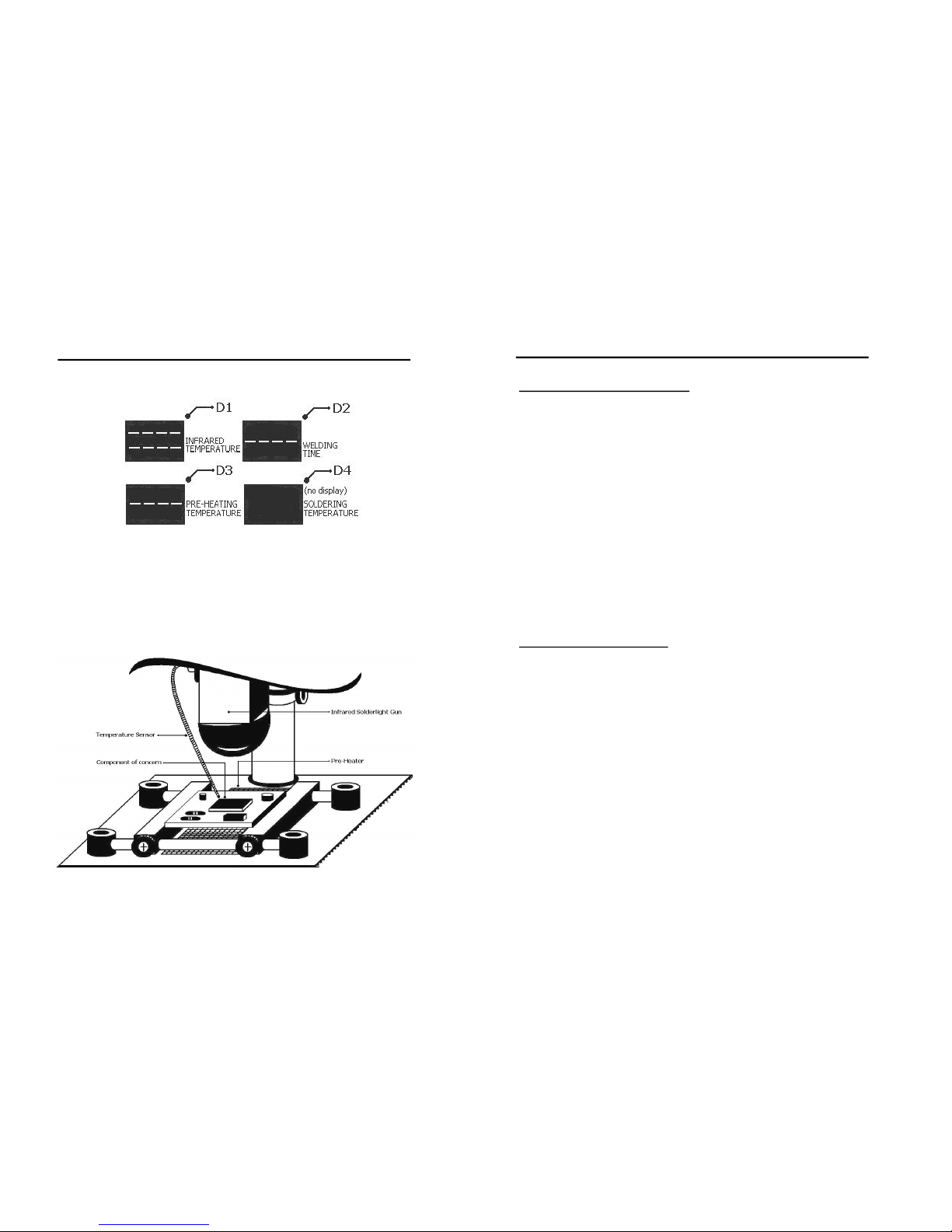
4. WithbuttonsC1,C4,C7,andC10disabled(OFF),thedisplaypan
elswillshowthefollowing.
5. ThePCB/componenttoberepairedshouldbeplacedontopofthe
preheatingcomponent.UsethebeamstoholdthePCBandadjust
the screws to secure the placement. Make sure that the affected
component is placed at an appropriate distance, perpendicular to
the IR solderlight gun. Thiswill keep the IRlight focused only to
the component concerned. Move the temperature sensor tip near
thecomponentfortemperaturereading.
OPERATINGPROCEDURES
15
USINGTHESOLDERINGIRON
1. WiththeunitswitchedONandthesolderingplugconnectedtothe
equipmentviaterminalEfromthecontrolpanel,activatesoldering
bypushingbuttonC10.
2. AdjustthesolderingirontemperatureusingbuttonsC11andC12.
3. Waitforafewsecondswhilethesystemisadjustingthesoldering
irontemperaturetothedesiredvalue.Youwillheara“beep”ora
highpitchsoundwhenthetemperatureisreached.
4. Whenworkisfinished,deactivatesolderingswitch.
5. TurnOFFtheunit.
6. Unplugthedevicefromthemainpowersource.
NOTE: The soldering iron temperature is configurable from 200 to
480C,with350Casthedefault.
USINGTHEFOOTSWITCH
1. Before reworking, make sure the unit is switched ON, the foot
switchconnectedtothedeviceviafootswitchplug,Ffromthecon
trolpanel,thePCBisproperlyplacedontopoftheequipment,and
thepreheattemperatureisreached.
2. Set the temperature by temporarily activating IR welding switch,
C1, and increase or decrease the desired reworking temperature
usingbuttonsC2andC3.
3. Oncetemperatureisset,deactivateC1.
4. Steponthefootswitchtostartreworking.
5. Whenfinished,turnoffthedevice.
6. Unplugtheunitfromthemainpowersource.
OPERATINGPROCEDURES

14
OPERATINGPROCEDURES
B.AutomatedweldingusingtheFOOTSWITCH
1. Before reworking, make sure the unit is ON, the footswitch con
nected to the device via footswitch plug, F, the PCB is properly
placed on top of the equipment, and the preheat temperature is
reached.
2. Set the temperature by temporarily activating IR welding switch,
C1, and increase or decrease the desired reworking temperature
usingbuttonsC2andC3.
3. Oncetemperatureisset,deactivateC1.
4. Set the reworking time by selecting buttons C5 and C6 from the
controlpanel.Notethatthetimeisinsecondsunit.
5. Activateautomateswitch,C4.
6. The countdown will startwhen youstep on the foot switch. Re
leasingthefootswitch,ontheotherhand,willholdthecount.This
willresumewhenyousteponthefootswitchagain.
NOTE: Timeisconfigurablefrom20to9999secondswitha20second
increment.
USINGTHERESETBUTTON
IMPORTANT: BecarefulinusingtheRESETbuttonasthiswillremove
all previouslydefinedconfigurations.Thiswill alsorestorethesystem
defaultvaluesasfollows:
IRsolderlightguntemperature: 90C
Automatetime: 300sec.
Preheattemperature: 200C
Solderingirontemperature: 350C
11
6. StartthepreheaterbyenablingorturningONbuttonC7fromthe
panel. The preheater will gradually increase the temperature to
200C,whichisthedefaulttemperaturevalue.Youmayfurtherin
creaseordecreasethetemperaturebypushingbuttonsC8andC9.
NOTE: If the preheating temperature display panel, D3, shows
“OFFC”duringthecourseofpreheating,pushtheRESETbutton,
B,toshowagaintheactualpreheattemperaturevalue.
7. Oncethedesiredpreheat temperatureisreached,youmaystart
the IR solderlight gun. Push button C1 from the control panel to
activate this. The infrared temperature display, D1, should show
somethinglikethefigurebelow.
The upper halfofthedis
playindicatesthedefaultoutputvalueoftheIRsolderlightgun,
whichis90C.Thelowerhalfindicatestheactualtemperaturede
livered to the component. You will notice that this value will
change frequently and will fluctuate a little above or below the
definedtemperaturelevel.UsebuttonsC2andC3toincreaseor
OPERATINGPROCEDURES

12
After the temperature has been set, the IR solderlight gun will
strikealightbeamonthecomponentforabout3secondsandwill
fadeafterwards.Thiswillrecurperpetuallyevery15secondsuntil
any of the following conditions is met: (1) the infrared welding
switch is turned OFF by the user, OR (2) once the predefined
automateweldingtimehaselapsed(see“USINGTHEAUTOMATED
WELDINGFUNCTION”),OR(3)whenthefootswitchhasbeende
activated(see“USINGTHEFOOTSWITCH”).
8. LeavetheIRsolderlightgunworkinguntilthecomponentis com
pletelydesolderedorwhenreworkingisdone.
9. Deactivate the infrared welding switch, C1, when rework is com
pleted.Notethatthesystemwillwaitforthetemperaturetodrop
to90CbeforeitcompletelyturnsOFF.Youwillalsonoticeaslight
change on the display panel like below while the temperature is
graduallydecreasing(i.e.,“Exxx”insteadof“bxxx”).
10. Deactivate the preheating button, C7, to cool down the pre
heatingelement.Thepanelwillthenshowtheinitialdisplayasin
itemnumber4onceeverythingissettled.
11. SwitchOFFtheequipmentusingbuttonAfromthecontrolpanel.
12. Unplugtheequipmentfromthemainpowersource.
OPERATINGPROCEDURES
13
REMINDERS:
●Always place the PCB on board supports or beams, with
thecomponentpositionedatthecenterofthepreheater.
●Alwaysapplyfluxtojointsbeforereflow.
●Before replacing a component, check if there is enough solder
onthe padstosoldernewcomponent.
●When replacing a component, make sure the new component
doesnothaveanybentleads.
USINGTHEAUTOMATEDWELDINGFUNCTION
IMPORTANT: TheautomatedweldingfunctionwillONLYworkifthe
infraredweldingswitchisONORwhenthefootswitchisactivated.
A. AutomatedweldingusingINFRAREDWELDINGswitch
1. Beforereworking,makesuretheunitis ON, thePCBisproperly
placedontopoftheequipment,andthepreheattemperatureis
reached.
2. SetthereworkingtimebyselectingbuttonsC5 andC6fromthe
controlpanel.Notethatthetimeisinsecondsunit.
3. ActivatetheIRweldingtemperatureusingbutton,C1,andadjust
thetemperaturebyselectingbuttonsC2andC3.
4. Activateautomateswitch,C4.
5. TheIRsolderlightgunwillworkuntilthetimehaselapsed.
NOTE:
●Time is configurable from 20 to 9999 seconds with a 20second
increment.
●ThecountdownwillpauseifC1buttonisdisabledwhileC4isON.
ItwillresumeonceC1isenabledagain.
OPERATINGPROCEDURES
Table of contents
Other aoyue Welding System manuals
Popular Welding System manuals by other brands

Chicago Electric
Chicago Electric MIG 170 Owner's manual & safety instructions

Draper
Draper 70057 quick start guide

GYS
GYS CUTTER 45 CT manual

Abicor Binzel
Abicor Binzel ROBO WH W600 Complete Manual and Package Insert

HBS
HBS A 12 operating manual

Eastwood
Eastwood MIG 140 Assembly and operating instructions

WeldCorp
WeldCorp MULTI PULSE PRO 240 Owner's operating manual

Klutch
Klutch ST80i owner's manual

Lincoln Electric
Lincoln Electric SQUARE WAVE IM565-B Operator's manual

Hypertherm
Hypertherm HT2000 instruction manual

Parkside
Parkside PESG 120 A1 operation and safety notes original operating instructions

Lincoln Electric
Lincoln Electric POWER WAVE IM956-A Operator's manual