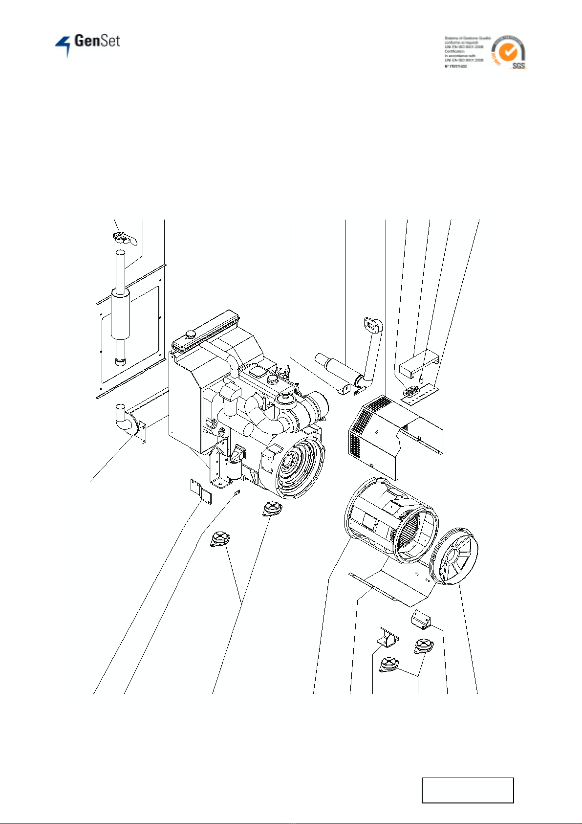
Motosaldatrice - Engine Driven Welder MPM 20/600 P
9MI499-03-00-00
Settembre 2007
Numero
Posizione
Item N°
Numero
Codice
Orderin
g N°
Descrizione Denomination
1 20.464 Segnale luminoso fuorigiri motore Overspeed alarm lamp
2 10.265 Segnale luminoso riserva carburante Low fuel level alarm lamp
3 16.959 Segnale luminoso temperatura acqua Coolant high temperature alarm lamp
4 19.458 Segnale luminoso pressione olio Oil low pressure alarm lamp
5 10.264 Segnale luminoso carica batteria Battery charger fault lamp
6 10.379 Presa di corrente 400 V 32 A 400 V 32 A outlet
7 17.812 Presa di corrente 230 V 32 A 230 V 32 A outlet
8 11.451 Presa di corrente 230 V 16 A 230 V 16 A outlet
9 28.235 Protezione termici Circuit breakers protection
10 0984 Connettore 3 poli 3 poles connector
11 28.516 Cerniera Hinge
12 28.517 Spessore cerniera Hinge shim
13 28.319 Perno per sportello Frontal door pin
14 28.518 Mostrina serigrafata Aluminium plate
15 26.274 Manopola D.45 D.45 knob
16 26.095 Potenziometro 1 K 1 K potentiometer
17 14.764 Trasformatore Transformer
18 18.576 Pannello elettronico GS9603 GS9603 electronic panel
19 22.434 Deviatore 2 poli 2 poles switch
20 910 Deviatore T210 T210 switch
21 28.504 Distanziale per termico Circuit breaker spacer
22 632 Termico unipolare 16 A 16 A 1pole circuit breaker
23 0749 Termico unipolare 32 A 32 A 1pole circuit breaker
24 23.008 Supporto termici Circuit breakers support
25 915 Interruttore differenziale quadripolare
40 A 40 A 4 poles earth leakage circuit
breaker
26 15.239 Contaore Hour meter
27 21.054 Pannello elettronico GS9801 GS9801 electronic panel
28 0336 Rele’ 12 V 12 V relay
29 28.505 Supporto pannello elettronico
GS9801 GS9801 electronic panel support
30 13.424 Interruttore di sicurezza Safety switch
31 28.519 Supporto interruttore di sicurezza Safety switch support
32 - Chiave avviamento Starting key
33 322 Voltmetro 300 V 300 V voltmeter
34 28.498 Lamiera portastrumentazione Electric equipment plate
35 22.433 Or O-ring
36 11.688 Indicatore livello carburante Fuel level indicator