Genelec 5041A User manual

Operating Manual
5041A Genelec 5041A
Active In-Wall Subwoofer

General
The Genelec 5041A Active In-Wall subwoofer
system consists of a subwoofer enclosure
and a matched RAM3 remote amplifier
module. It has been designed to the same
rigorous standards as Genelec’s high-per-
formance HT series active Home Theater
loudspeakers.
Unpacking
When unpacking, check that nothing is miss-
ing or damaged in transit. If there is a problem
with the product, contact your local Genelec
dealer. A Genelec 5041A system includes
the following items:
• 5041Aenclosureunit
• Grilleframeandgrilleinsert
• Fourmountingbrackets
• RAM3amplierunit
• M4x16 and M4x30 thumb screws
for the grille frame
• Plasticwashersforthethumbscrews
• Mainspowercable
• One 4-pole and one 2-pole cable
connector
• 12 4,2x32 screws for the mounting
brackets
Installation
We recommend that you use the services of
an authorized installation specialist for the
installation of the 5041A subwoofer.
Choosing the Location
for the Subwoofer
Usually the best place for the subwoofer is
slightly offset from the centerline of the wall.
Positioningthesubwoofernearacornerwill
boost the bass level at lower frequencies and
may cause asymmetrical spatial imaging.
When using multiple subwoofers connected
togetherusingtheLINKOUTconnectorson
theRAM3ampliers,thesubwooferenclo-
sures should be placed close to one another
toachieveefcientsummingofthesignal.
Subwoofer Cabling
A2-conductorcableneedstoberunbetween
theRAM3amplierandthesubwooferenclo-
sure. Two cable connectors are supplied with
the loudspeaker system, a four-pole connec-
tortottheconnectorontheamplieranda
two-poleconnectortottherespectiveinput
at the bottom of the subwoofer enclosure.
Useagoodquality2-conductorcableand
make the cable runs as short as possible.
See Table 1 for recommended cable gauges.
Theconnectorsacceptacableupto6mm2
(9 gauge) thick.
Attach the cables to the connectors pro-
vided with the kit. Be sure to maintain cor-
rect polarity when connecting the cables.The
correct pin sequences are marked on the
amplierandsubwooferconnectors.Start-
ingfromthetop,thersttwopolesonthe
4-poleamplierconnectorare+and-forthe
subwoofer and 3 and 4 provide connection
toa12Vtriggerremotecontrol.Securethe
cabletothestrainrelieftienexttotheloud-
speaker connector.
Rout the cables away from electric, video
or phone cables, which might induce hum
into the system.
Installing the Subwoofer
Enclosure
The Genelec 5041A subwoofer enclosure
is designed for floating installation using
the provided mounting brackets that pre-
vent unwanted vibration transfer from the
subwoofer to the wall structure. The enclo-
sure is held in place by rubber springs, clear
ofanyxedpartofthewall.
The woofer protection cover should be
left in place until the drywall is installed. It
provides a cut-out template for the drywall
installers and protects the bass drivers during
all stages of work.
Before the installation, make sure that
thereissufcientspaceforthesubwoofer
in the chosen location. The minimum dimen-
sions are:
1.Freedepthbetweenthesheetrock(=width
of the wall studs) 89 mm (31/2")
2.Freeverticalspace1308mm(511/2")
3. Freehorizontalspace betweenthe wall
studs360to440mm(143/16" to 173/8")
Firstattachthetwolowerbrackets.Note
that the lower edge of the cut-out will be
140 mm (51/2") above the lowest edge of the
bracket.
The flanges on the bracket correspond to
the minimum permissible mounting depth.
Attach the brackets to the studs so that the
edge of the flange is level with the inside
edge of the stud. This will automatically pro-
videsufcientclearanceforthesubwoofer.
Nextconnectthesubwoofercabletothe
connector at the bottom of the subwoofer
enclosure and position the enclosure on the
lower brackets. The rubber springs on the
brackettthegroovesonthebottomofthe
enclosure.
Secure the subwoofer in place by attach-
ing the top brackets to the studs. Align them
in the same way as the lower brackets and
ensure that the rubber springs press against
the bottom of the grooves, holding the
subwooferrmlyinposition.
Check the positioning of the enclosure
by placing a level on the studs at different
heights. Check also that the enclosure is not
touching any other part of the wall structure.
As the enclosure may vibrate when played
at high output levels, a clearance of at
least 3 mm (1/8") is required between the
subwoofer enclosure and drywall or any
other solid part of the wall. Slight adjust-
ments can be made by carefully bending
the brackets.
Installing the drywall
The protective cover on the bass drivers pro-
vides a template for the cut-out. Measure its
location and cut an opening in the sheetrock
accordingly.
Installing the Grille
Once the drywall is installed, remove the
bass driver protective cover by unscrewing
thethreePhillipsscrewsholdingitinplace.
Attach the grille frame with three thumb
screws.NEVERusethePhillipsscrews!Do
not tighten the thumb screws more than is
needed to hold the frame in place. Be care-
Cable gauge Max.length
2,0mm2(14 AWG) 30 m (100 ft)
3,3 mm2(12AWG) 40 m (130 ft)
5,3 mm2(10 AWG) 60m(200ft)
Table 1. Recommended cable thicknesses for
different lengths of cable
Genelec 5041A Active In-Wall Subwoofer
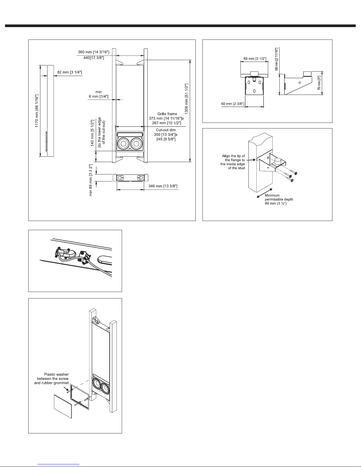
Figure1.5041Asubwooferenclosuredimensions
Figure2.Enclosuremountingbracketdimensions
Figure3.Aligningandattachingthemountingbrackets
Figure4.Attachingthesubwoofercable
ful not to flatten the vibration isolating rubber
grommets on the grille frame by overtighten-
ing the screws.
Insert the grille insert to the grille frame.
PaintingtheGrille
The grille frame and the grille insert can be
spraypaintedtomatchthewallcolour.Paint
the grille frame and insert separately with a
thinspray.Donotusebrushesorrollers.Be
careful not to clog the holes on the insert with
paint.
Connecting the
RAM3 Amplifier
TheRAM3amplierisdesignedtobecon-
nectedtoalineleveloutputofapreamplier,
Surround Sound processor or other low level
source. NOTE! Never connect the RAM3 to
a speaker level output of a power amplifier!
Before making the connections, check that
the power on all components is turned off.
Start by connecting the subwoofer cable to
theamplierasdescribedinthe"Subwoofer
Cabling" section above. If using multiple
subwoofers,checkthattheamplier’sserial
number matches that of the subwoofer enclo-
sure which it will power.
TheRAM3hastwo10kOhmsignalinput
connectors: a balanced XLR and an unbal-
ancedRCA.Forlongcableconnectionlengths
(>10m or >30ft) a balanced line connection
is recommended as it offers better immunity
toexternalinterference.However,theRCA
connection method usually works as well for
shorter connection lengths in less electrically
noisyenvironments.Donotusebothinputsat
the same time. Your Genelec dealer can pro-
vide you with options for signal cables.
The RAM3 has a provision for remote
controlled switching between “ON” and
“STANDBY”modes. Poles 3and 4on the
green connector block provide connection to
a12Vremotecontroltrigger.
Space Requirement for the
RAM3 Amplifier
TheRAM3amplier generatesheatwhen
used at full power. To avoid overheating,
ensure that there is good airflow around the
amplierandnoexternalheatsourcesclose
to it. We recommend installing the RAM3 into
a well ventilated equipment rack using its
dedicatedRM2rackmountkitwhichallows
airflow through the ventilation holes of the
amplierbox.Theampliermustalwaysbe
installed in an upright position, never flat on
its side.
Figure5.Installingthegrilleframeandinsert
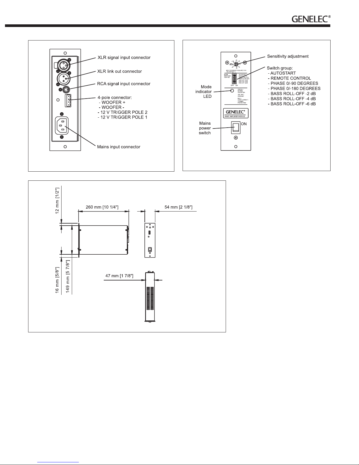
Figure6:ConnectorlayoutonthebackpaneloftheRAM3amplifier Figure7:RAM3frontpanellayout
Figure8:DimensionsoftheRAM3amplifier
Sufcientcoolingfortheampliermustbe
arranged at all times. As a general rule, the
ambient temperature around the amplifier
mustnotexceed35degreesCelsius(95°F).
The ventilation openings on the amplifier
boxmustnotbeblockedandafreespaceof
1U(=1.75"or45mm)mustbeleftabove
theamplierwheninstalled.Thisspacemust
besufcientlyventilatedtomaintainthetem-
peraturebelowthemaximumlevel.
IftheRAM3amplierisplacedonashelf
or other solid surface, the metal support
providedwiththeampliermustbeattached
tothelowerpartoftheamplierfrontpanel
with an M4 screw. This improves the stability
oftheamplierandprovidessufcientclear-
anceforaircirculationbelowtheamplier.
Rack Mounting the RAM3
Amplifier
WerecommendusingtheGenelecRM2rack
mount adapter when installing the RAM3
amplierinanequipmentrack.Makesure
that the space above and below the RAM3 is
uncluttered and there is a space of 100 mm
(4”)ormorebehindtheamplier.Thespace
behindtheampliermustbewellventilated.
If the temperature inside the rack is likely to
riseclosetothemaximumambienttempera-
tureof35°C(95°F),werecommendinstall-
ing ventilation fans to ensure that the thermal
protection is not activated prematurely.
AttachtheRAM3totheRM2rackmount
with two M4 screws provided with the rack
mount kit.
Setting the Input Sensitivity
The input sensitivity control is located on the
frontpaneloftheRAM3amplier.Usethis
control to adjust the playback level of the
subwoofer.
SettingtheBassRoll-Off
switches
The acoustic response of the subwoofer may
have to be matched to the characteristics
of the room and its position in the room. To
adjust the subwoofer to match these charac-
teristicsusethe"BASSROLL-OFF"control
switcheslocatedontheamplierfrontpanel.
WhenallRoll-Offswitchesare"OFF",aat
anechoic response is obtained.
Setting the phase control
The effect of incorrect phase align-
ment between the main loudspeakers
and subwoofer is a drop in the frequency
response of the whole system at the main
loudspeaker / subwoofer crossover fre-
quency. The phase difference between the
main loudspeakers and subwoofer at the lis-
tening position is dependent upon the posi-
tion of the subwoofer.
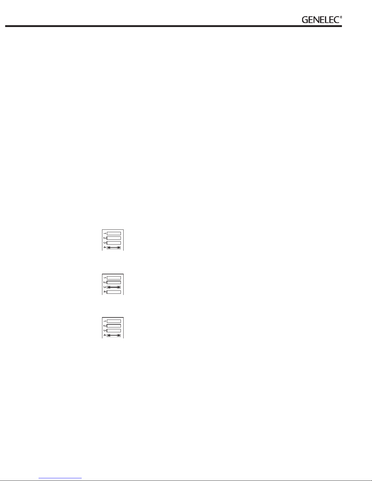
Two phase matching switches in the
crossover allow compensation for incorrect
phasealignment.Foursettingsareprovided
between0°and-270°.
Coarse phase correction
method
• Conguretheprocessorsothatthemain
speakers(L,C,R)aresetto“small”and
check the main speaker/subwoofer
crossover frequency setting on your
processor. This frequency may be
variableorxed:consulttheoperating
manual of your processor.
• Connectanaudiosignal
generator to one of the input channels
used in the system.
• Setthesignalgeneratortothesame
frequency as the subwoofer crossover
frequency on your decoder. If a signal
generator is not available, you can use an
audio test recording with a suitable range
of test frequencies.
• Togglethe-180°phase
switch(#4)"ON"and"OFF"
and set it to the position
which gives the lowest sound
level at the listening position.
• Nexttogglethe-90°phase
switch(#3)"ON"and"OFF",
and again set it to the
position which gives the
lowest sound level.
• Finally,setthe-180°phase
switch to the opposite setting.
After the phase setting has been completed,
returnthespeakercongurationontheproc-
essor to its’ original settings.
Using multiple subwoofers
The5041Aisequippedwitha“LINKOUT”
connector to provide an easy way of cou-
pling two or more subwoofers together in
high SPL applications. Connect an XLR
cablefromthe“LINKOUT”connectorofthe
master subwoofer to which the decoder is
connected,tothe"XLRIN”inputconnec-
tor of the other, slave subwoofer. When
two subwoofers connected in this way
are positioned close to one another, bass
levelincreasesby6dB.Threesubwoofers
givea bass SPL increase of9,5dBand
foursubwoofersprovidea12dBincrease
compared to a single subwoofer. Adjust the
sensitivity control of all subwoofers in the
grouptomatchtheSPLlevelofthemain
loudspeaker system. Note that the sensitiv-
ity setting must be the same on all subwoof-
ers.
Autostart and Remote
ControlFunction
The 5041A is equipped with an “AUTO-
START” function, which automatically
turnstheamplierto“STANDBY”modeif
an input signal has not been detected for
approximately30minutes,andbackto“ON”
mode when the signal returns. The function
canbedeactivatedbyturningthe“AUTO-
START”dipswitchto“OFF”.Atwo-colour
LEDon the amplierpanelindicates the
amplierstatus:greenfor“ON”andyellow
for“STANDBY”.
Theampliermodecanalsobeswitched
bya12Vtriggertyperemotecontrol unit
connected to the respective inputs on the
amplier(see"SubwooferCabling").Switch
the“REMOTECONTROL”dipswitchto“ON”
to activate this function. Remote control over-
ridesthe“AUTOSTART”function.
AutomaticProtectionCircuits
The 5041A is equipped with protection cir-
cuits against bass driver thermal overload
and amplifier overheating. The protection
system resets automatically so that the user
only has to turn the input level down to ensure
that it does not reactivate.
Safety considerations
The Genelec 5041A complies with interna-
tional safety standards. However, to ensure
safe operation and maintain the equipment in
safe operating condition the following warn-
ings and cautions must be observed.
• Servicingandadjustmentmustonlybe
performedbyqualiedservicepersonnel.
• Openingtheamplierisstrictly
prohibitedexceptbyqualiedservice
personnel.
• Donotexposethesubwooferoramplier
towaterormoisture.Donotplaceany
objectslledwithliquid,suchasvaseson
or near them.
• Alwaysuseamainspowercableand
connectionwithprotectiveearth.Failing
to do this may lead to personal injury.
• Notethattheamplierisnotcompletely
disconnected from the AC mains service
unless the mains cable is removed from
theamplierorthemainsoutlet.
Warning!
This equipment is capable of delivering sound
pressurelevelsinexcessof85dB,which
may cause permanent hearing damage.
Maintenance
There are no user serviceable parts inside
the amplifier or subwoofer enclosure. Any
maintenance of the unit must only be per-
formedbyqualiedservicepersonnel.
Guarantee
This product is supplied with two year guaran-
tee against manufacturing faults or defects that
might alter the performance of the unit. Refer
to supplier for full sales and guarantee terms.

ECDeclarationofConformity
This is to certify that the Genelec 5041A Active In-Wall
Subwoofer conform to the following standards:
Safety:
EN60065:2002+A1:2006/IEC60065:20017thEdition
+A1:2005
EMC:
EN55013(2001)+A1(2003)
EN55020(2002)+A1(2003)
EN61000-3-2(2000)+A2(2005)
EN61000-3-3(1995)+A1(2001)
The product herewith complies with the requirements of
TheLowVoltageDirective2006/95/ECandEMCDirective
2004/108/EC
Signed:
Ilpo Martikainen
Position: Chairman of the Board
Date: 25-September-2008
GenelecDocumentD0079R001CopyrightGenelecOy9.2008.Alldatasubjecttochangewithoutpriornotice www.genelec.com
International enquiries:
Genelec,Olvitie5
FIN-74100,Iisalmi,Finland
Phone+3581783881
Fax+35817812267
Email [email protected]
In the U.S. please contact:
Genelec, Inc., 7 Tech Circle
Natick,MA01760,USA
Phone+15086520900
Fax+15086520909
Email [email protected]
In Sweden please contact
Genelec Sverige
Ellipsvägen 10B
P.O.Box5521,S-14105Huddinge
Phone+4684495220
Fax+4687087071
Email [email protected]
In China please contact:
Beijing Genelec Audio Co. Ltd.
JianwaiSOHO,Tower12,Room2306
39 East 3rd Ring Road
ChaoyangDistrict
Beijing100022,China
Phone+86058697915,Fax+861058697914
5041AOperatingManual
AMPLIFIER SECTION
CONNECTORS
SYSTEM SPECIFICATIONS
5041A
Freeeldfrequencyresponse(±3dB) 35 Hz...95 Hz
MaximumshorttermsinewaveSPLoutput
averaged from 40 to 85 Hz, measured in half
space at 1 meter
105 dB
MaximumpeakSPLoutputwithrandompink
noise, measured in half space at 1 meter
110 dB
Self generated noise level in half space at 1 m
onaxis(A-weighted)
≤ 15 dB
Drivers 2x165mm(6.5")
Weight
Subwoofer enclosure
Amplier
15 kg (33 lb)
1.4 kg (3.1 lb)
Dimensions(seeFigure1)
Subwoofer enclosure
Height
Width
Depth
Amplier
Height
Width
Depth*
*Notethatthecableconnectorsrequireat
least100mm(4”)ofspacebehindthe
amplier
1170mm(461/16”)
346mm(135/8”)
82mm(31/4”)
177mm(631/32”)(4U)
54mm(21/8”)
260mm(101/4”)
5041A
Ampliershorttermoutputpower
(Long term output power is limited by driver
unit protection circuitry)
125W
AmpliersystemTHDatnominaloutput ≤ 0.05 %
Mains voltage 85-132Vor170-265V
according to region
Powerconsumption(average)
Stand by
Idle
Fulloutput
8.5VA
11VA
150VA
5041A
Input connector XLR female
pin 1
pin2
pin 3
1, balanced
gnd
+
-
Input connector RCA female
pin 1
pin2
1, unbalanced
gnd
+
LINKOUTconnectorXLRmale
pin 1
pin2
pin 3
1, balanced
gnd
+
-
Input impedance 10kOhm
LINKOUTgain 0 dB
CONTROLS
5041A
Input sensitivity +12to–6dBu
Phasematchingcontrolin90°steps From0to-270°
BassRoll-Offcontroloperatingrange
in2dBsteps
From0to-6dB@35Hz
Remote control Remote controlled
Standby/Onswitchingby
12Vtrigger
This manual suits for next models
1
Table of contents
Other Genelec Subwoofer manuals

Genelec
Genelec 7050C User manual

Genelec
Genelec 7350A User manual

Genelec
Genelec 5040B User manual

Genelec
Genelec 1091A User guide

Genelec
Genelec SE7261A User manual

Genelec
Genelec 7000 Series User manual

Genelec
Genelec 7300 Series User manual

Genelec
Genelec F Two User manual

Genelec
Genelec 5050A User manual

Genelec
Genelec 1092A User manual

Genelec
Genelec 7060B User manual

Genelec
Genelec F One User manual

Genelec
Genelec AutoCal 7260A User manual

Genelec
Genelec 7350APM User manual

Genelec
Genelec 5040A User manual

Genelec
Genelec 7060B User manual

Genelec
Genelec 7050A User manual

Genelec
Genelec 5040A User manual

Genelec
Genelec 1094A User guide

Genelec
Genelec 7050C User manual


