General Description
TheGenelec1094Aand1092Aactive
subwoofersarepowerfullowfrequency
loudspeakers, incorporating all the
amplifier and crossover electronics
needed to combine them with other
loudspeakers and amplifiers.
Drivers
The 1094A contains a single 385mm
(15") long throw cone driver, housed
in a 110 litre vented cabinet. A cavity
over the driver boosts the drivers
efficiencyandacousticallyattenuates
possible distortion components. The
1092A utilises two 210mm (8") cone
drivers, housed in a 55 litre vented
cabinet, and employs driver front
loading.
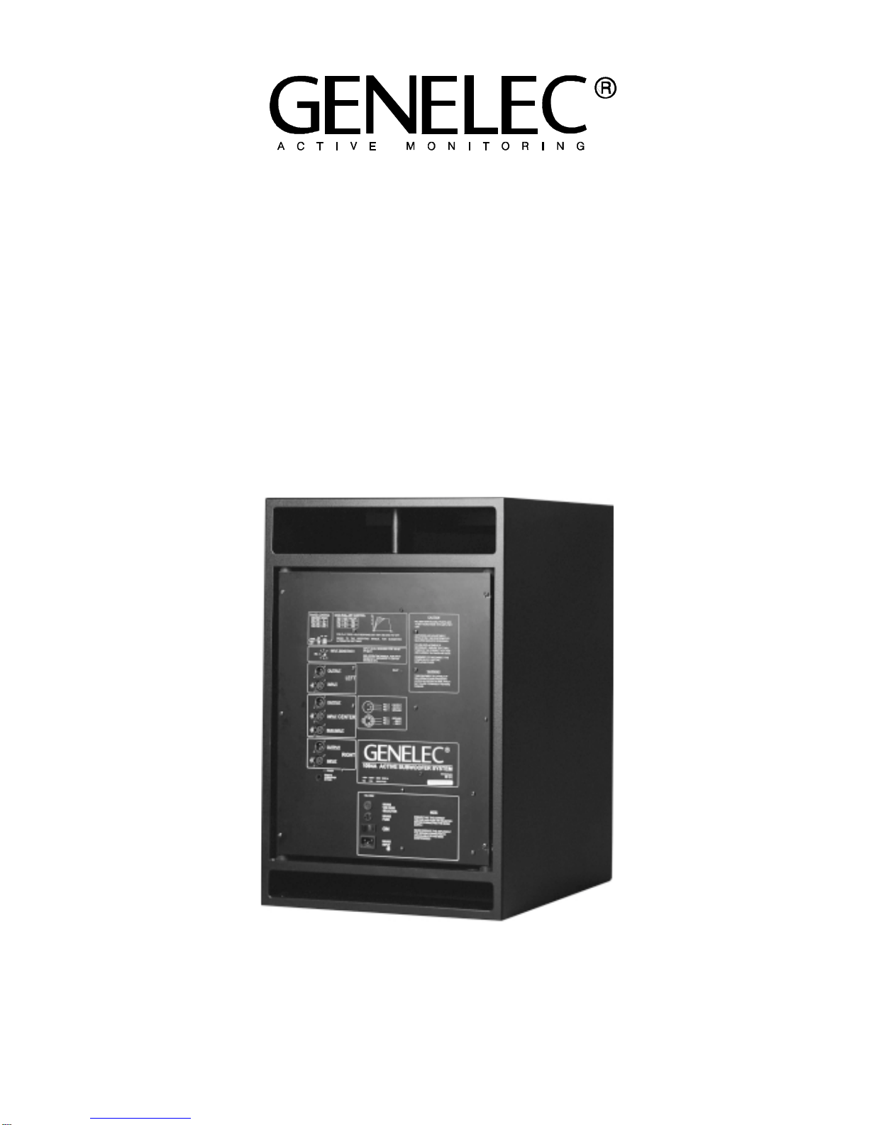
Crossovers
The 3+1 channel active crossover
within the amplifier unit filters the low
andhighfrequencycomponentsofthe
threefrontchannels,dividingtheinput
signals between the subwoofer and
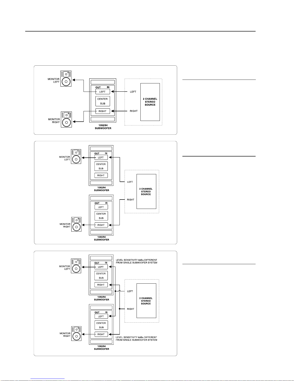
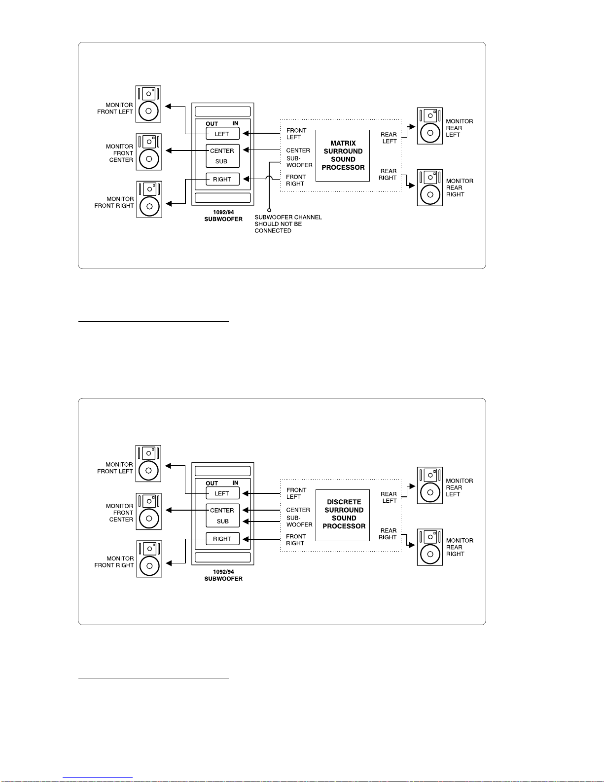
the main monitors. A separate
subwoofer input connector allows for
complete compatibility with digital 5.1
channel surround sound systems.
The crossover filter also provides
calibrated ‘Bass Roll-off’ and ‘Phase’
controls, minimising the effects of the
room on the performance of the
subwoofer.
Amplifiers
The amplifier unit is mounted in the
rear of the cabinet on quick release
vibrationisolatorstoensurerattlefree
operation and long term reliability.
The1094Aand1092Aamplifieroutput
powers are 400W and 180W
respectively. The amplifiers
incorporate special driver protection
circuitryfordriveroverloadprotection.
Table 1. Suggested Bass Roll-Off switch settings.
Room Type Bass Roll-Off
Sw1 (-2dB) Sw2 (-4dB)
Flat Anechoic Response OFF OFF
Positioned near a wall ON OFF
Positioned in a corner ON ON
Installation
Each subwoofer is supplied with a
mainscableandanoperatingmanual.
Onceunpacked, placethe subwoofer
in a suitable position (for more details
see the 'Positioning' section).
Before connecting the audio signals,
ensure that both the subwoofer and
the main monitors are switched off.
Check that the subwoofer voltage
selector switch is set to the correct
voltage and that the correct fuse for
that voltage is fitted.
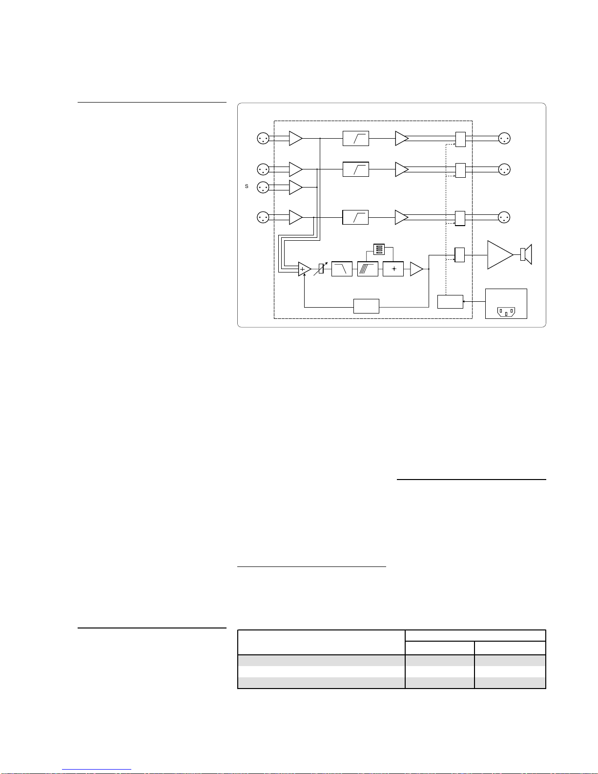
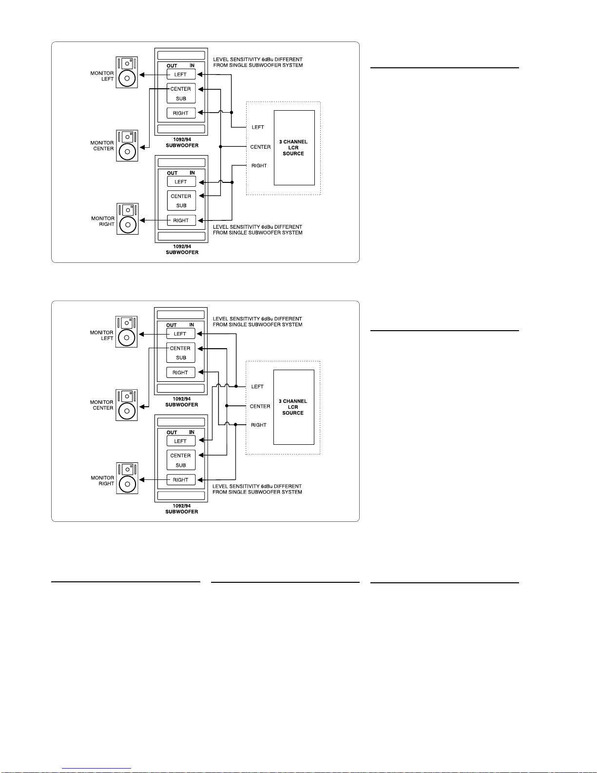
Audio connections to the subwoofer
are made via balanced XLR
connectors. Signals from the source
are fed into the subwoofer input
connectors and signals for the main
monitorsaretakenfromthesubwoofer
output connectors. Once all
connections have been made, the
subwoofer and main monitors are
ready to be powered up.
Setting the Input Sensitivity
The subwoofer requires input
sensitivity alignment to the mixing
console or other source to obtain a
correctly balanced system. The input
sensitivity control is located on the
rear panel of the subwoofer. An input
voltage of -6dBu with a -6dBu input
sensitivity setting will produce 100dB
SPL @ 1m. To obtain a 110dB SPL
output an input voltage of +10dBu is
required when the input sensitivity is
set to 0dBu.
Setting the Bass Roll-Off
Switches
The acoustic response of the
subwoofermayhavetobematchedto
the characteristics of room in which it
will be used. To adjust the subwoofer
to match these characteristics use
the ''Bass Roll-off' control switches
located on the rear panel of the
subwoofer. Table 1 provides some
suggestions for the 'Bass Roll-off'
switch settings. When both roll-off
switches are 'off', a flat anechoic
response results.
Genelec 1094A and 1092A Subwoofers
Figure1.FunctionalblocksofGenelec1094Aand1092ASubwoofers
H P 85 H z
Balanced
In p u ts
L
C
R
L
C
R
S e n s itiv ity
±6dB
Balanced
O utputs
0°
180°
Sta t/Stop
Mute
Pow e supply
cicuits
CRO SSO VER FILTER
D ive
P otection
Powe
A m p lifie
90°
270°
B ass
Roll-off
Phase
LP
85 H z