
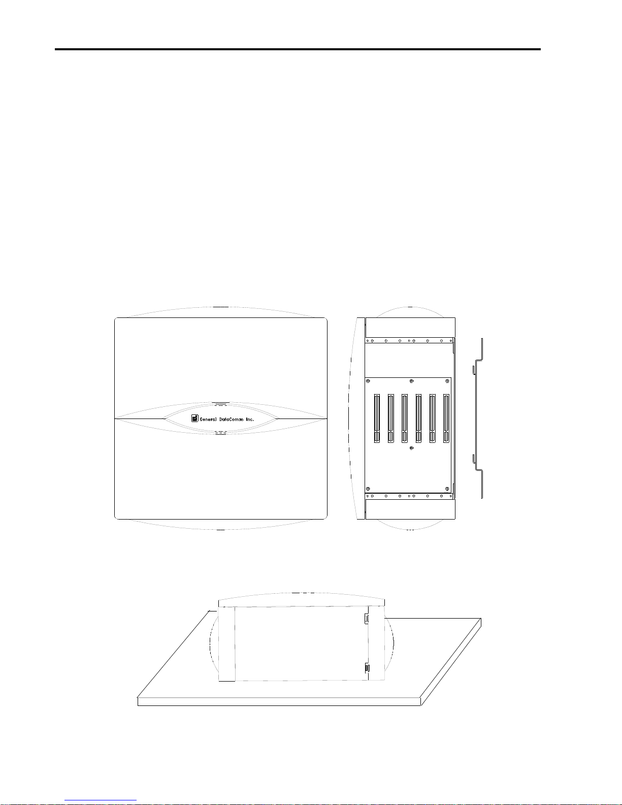
1-6 Wallmount Enclosure
GDC 086R601-001
Grounding for Safety and EMC
When AC powered, the enclosure must be connected to protective (earth) ground for safety
reasons. This is normally done via the power cord’s ground wire, or optionally via a separate
ground wire from a grounding post (chassis ground) on the rear panel.
Electromagnetic Compatibility (EMC) is maximized with the use of shielded cables for data
circuits. These shielded cables are connected to the chassis and thus to local earth ground. This
occasionally causes a problem if the equipment to which the unit is connected is at a different
ground potential than the unit.
A large ground current can flow in the shield of a shielded cable if it is connected to ground at
both ends, and the grounds at the two equipments are not at the same potential. To avoid large
currents, make sure that a potential difference of less than 0.25 V RMS exists between the ground
of the unit and the ground of the equipment to which it is connected. An alternative is to break
the shield continuity in the middle of a long cable run, or to connect the shield to ground at only
one end.
It is common practice to tie chassis ground and signal ground together. Signal ground is the 0V
reference for the digital circuits in the unit, and is also the reference for unbalanced data interfaces
such as EIA/TIA-232-E and RS423. Tying these grounds together is usually best for AC power
line noise immunity, but a problem can exist if signal grounds on two equipments (at different
chassis ground potentials) are connected together via a data cable. A large current can flow in the
signal ground lead (EIA/TIA-232-E pin 7). To prevent this, make sure the potential difference
between grounds is less that 0.25 V RMS.
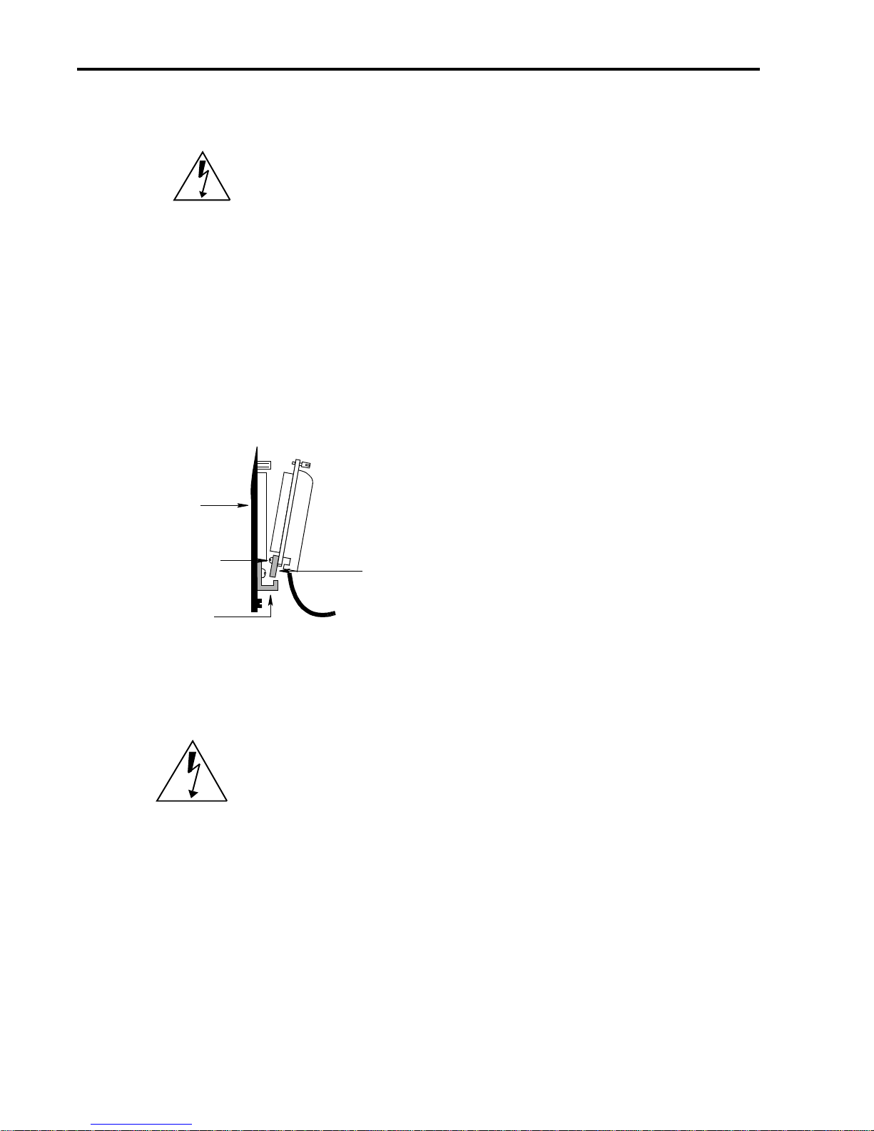
Chassis Grounding Post
The enclosure chassis is normally grounded through the ground lead of the IEC 320 AC
input receptacle. In addition, the chassis may be grounded by connecting a 16 AWG
minimum wire from the chassis grounding post, marked by the symbol located as shown
in Figure 1-3. This wire should be connected to the Building Telecommunications Ground.
Signal Ground
Signal ground andChassis Ground may be tiedtogether by wiring between the two terminal block
positions labeled SIG GND and CH GND. The unit is shipped with these two grounds connected
by a jumper. If required, this jumper may be removed to isolate the grounds.
E&M Ground
If you are using voice channels with Type I or Type V E&M signaling, the rear panel terminal
block position labeled E&M GND must be connected to the signaling ground of the switching
equipment (PBX). This ground connection is only used with E&M signaling types I and V.
The unit is shipped with a jumper that connects E&M GND to Chassis Ground. If the Metroplex
6000 Chassis Grounding Post is connected to the switching equipment’s ground, this is sufficient
toprovidethe returnpath.Otherwise,removethisjumperandconnecta wirefromthe E&M GND
position directly to the switching equipment ground.


 user manual")


