The Hydraulic Platform is designed to give you years of trouble-free service but in the event of a failure, the
following procedures should be followed:
LOSS OF ELECTRICAL POWER OR FAILURE OF PUMP MOTOR
A Check circuit breaker usually located on the main DC circuit breaker panel in the engine room.
If the unit has been run repeatedly in a short period of time, let the unit cool down for 10 minutes and try the lift
again. In the event that your DC power supply or the pump motor fails, the lift cannot be operated in the “normal”
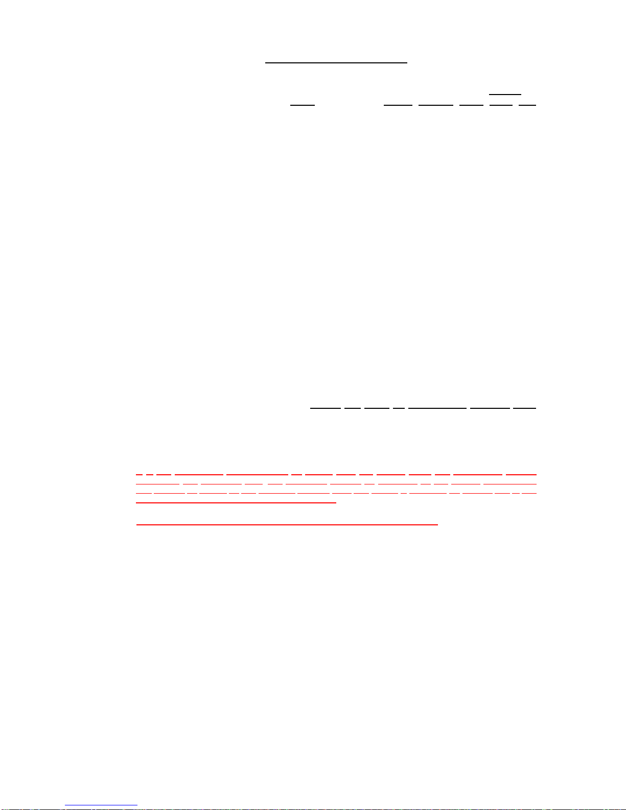
mode. It may be operated in the manual mode. To operate the unit in the manual mode, locate the Hydraulic
Power Unit Assembly (most often it is located in the engine room close to the transom) then do the following:
1 To manually raise the platform:
Insert the Emergency pump handle (black metal handle approx. 18” long) into the Manual Pump located on the
Hyraulic Power Unit (HPU). Turn the “knurled” red knob, located on the “UP” Solenoid, counterclockwise until it
pops up (about ¼ of a turn). You are now in the manual “UP” mode. Using the handle, pump until the unit is
completely up. You should hear the two locking cylinders engage the lock pins and the gage pressure should
approach 2500 PSI. When you are sure that the unit is locked in the up Position, push the red knob down &
clockwise until it returns to the original position. This procedure may take several minutes because of the low
flow rate of the hand pump. NOTE: When using manual mode, only one solenoid is allowed to be in “manual” at
a time.
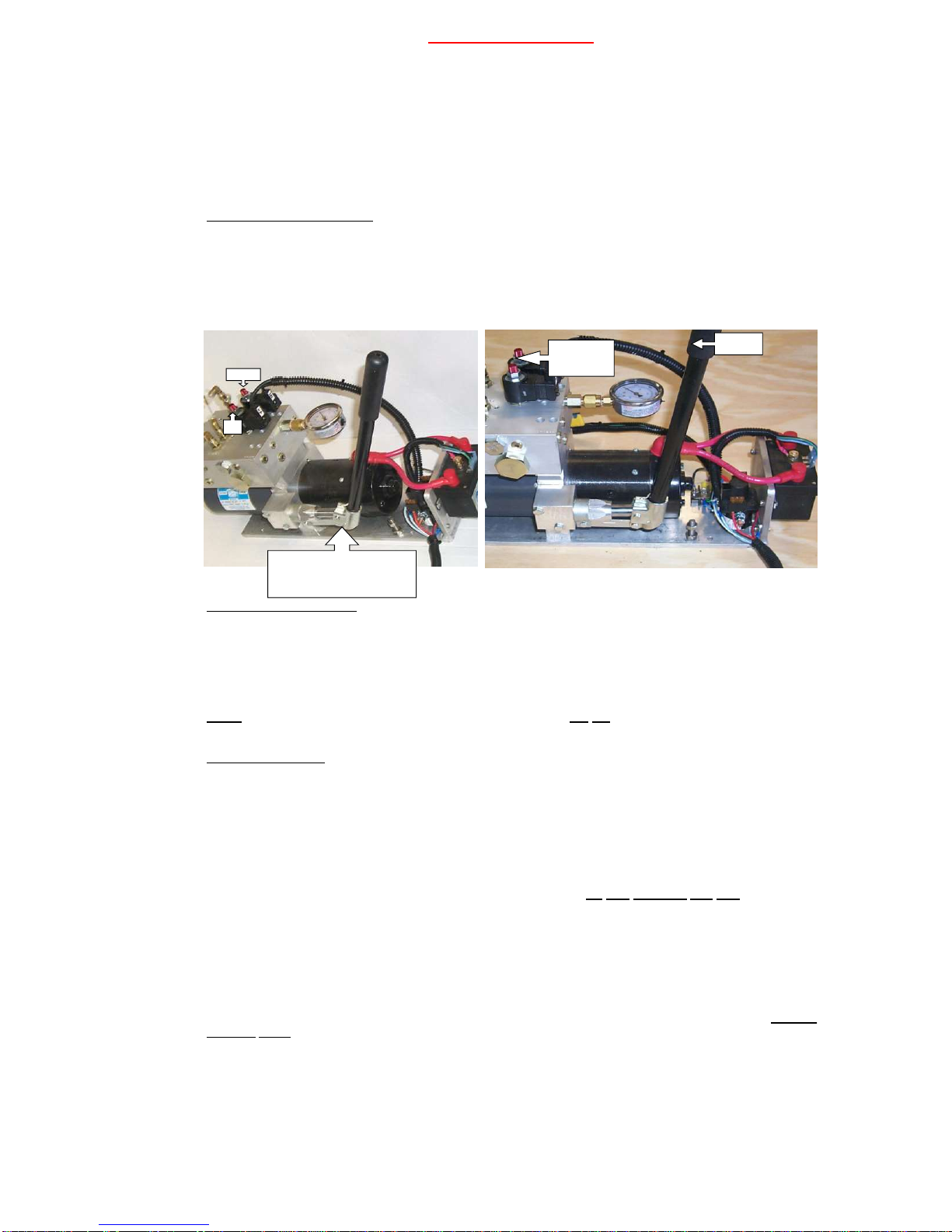
2 To manually lower platform:
Insert the handle (black metal handle, approximately 18”Long) into the Manual Pump located on the side of the
power unit. Turn the “knurled” red knob, located on the “DN” solenoid, counterclockwise until it pops up (about
¼of a turn). You are now in the manual “DN” mode. Pump the handle until the unit unlocks and lock plates are
clear of locking pins on arms. Adjust sequence valve all the way out (count turns of set screw to redo setting)
pump to desired depth. When you are sure that the unit is down to the desired depth, turn the red knob down &
clockwise until it returns to the original position, reset sequence valve. You are now back into the normal mode.
NOTE: When either of the manual modes are selected, the pump will not operate in the normal (electric) mode
even though the motor may run.
One side of the platform moves faster than the other side.There is a possibility that one side of platform will move
at a different rate than the other. The Hydraulic Manifold contains combiner-divider valves (see page 17-31) that
regulate and equalize fluid flow to both lift cylinders. This valve is only 90% efficient, so you will notice some
slight difference in the movement of the individual sides. However this difference will be minimal and should not
affect the normal operation of the platform. If there is a significant difference in the rate of movement, try shifting
the load toward the faster side. If the problem persists, follow the recommendations in the “TROUBLE
SHOOTING GUIDE”.
4 LEAKING OR BROKEN HYDRAULIC LINE-DO NOT ATTEMPT TO OPERATE THE LIFT
If the platform is in the up position, and any line is broken or leaking DO NOT OPERATE THE LIFT. Contact your
dealer or GHS for help in determining if there is a serious problem. If the platform is down, it must be raised
before the engines are started. A broken or leaking hose must be replaced prior to operation.
5 PHYSICAL DAMAGE TO EITHER THE PLATFORM OR LIFT ASSEMBLY.
If the swim platform assembly has been damaged due to an accident etc., have the damage assessed by your
Dealer before operating the lift. Serious damage to the hull can result from operating the lift when it is
misaligned.
If the Lift should ever have any operational problems please reference the Owner’s manual /Trouble-
Shooting Guide to determine the cause of these problems and their solutions. General Hydraulic Solutions has all
necessary parts to help get your lift back in operation.
PUMP HANDLE INSERTED INTO