JJ
JJ
J 8
Spare Part List
Legend
EU = 230Vac Europe Version
US = 115Vac U.S. Version
B = Black Gloss Finish
M = Mahogany Finish
Baldwin = Baldwin version
Bachmann = Bachmann version
Code Description
Optional Accessories
130301 2mt Midi Cable
Accessories
271202 Owner’s Manual (All Languages)
130274 Mains Cable (EU)
130276 Mains Cable (US)
970297 Pianist’s Bench (B)
970319 Pianist’s Bench (M)
190193 * Hexagonal Rod Spanner
150618 * Thumbscrew
120523 * M 6 Black Grower Washer
120456 * M 6x1.5mm Black Washer
120070 * M 6x20mm Black Screw
Cabinet Assembly
Wooden Parts
261662 Front Panel (B) (specify Bachmann)
710568 Front Panel (M) (specify Bachmann)
261869 Sharp Key Strip (B) (specify Bachmann)
710567 Sharp Key Strip (M) (specify Bachmann)
261907 Lower Rear Panel (B)
261999 Lower Rear Panel (M)
261881 Upper Rear Bar (B)
261998 Upper Rear Bar (M)
261880 Left Foot (B)
261997 Left Foot (M)
261879 Right Foot (B)
261996 Right Foot (M)
261878 Left Leg (B)
261995 Left Leg (M)
261877 Right Leg (B)
261994 Right Leg (M)
261872 Rear Speaker Panel (B)
262016 Rear Speaker Panel (M)
261675 Pedals Cross Bar (B)
261993 Pedals Cross Bar (M)
261671 Lower Front Panel (B)
261992 Lower Front Panel (M)
261666 Cabinet Cover (B)
261991 Cabinet Cover (M)
261660 Cabinet Right Side (B)
261990 Cabinet Right Side (M)
261659 Cabinet Left Side (B)
261989 Cabinet Left Side (M)
261658 Keyboard Right Side (B)
261988 Keyboard Right Side (M)
261657 Keyboard Left Side (B)
261987 Keyboard Left Side (M)
261564 Music Stand (B)
261986 Music Stand (M)
261430 Left Cheek Block (B)
261985 Left Cheek Block (M)
261407 Right Cheek Block (B)
261984 Right Cheek Block (M)
261397 Revolving Keyboard Cover (B)
261983 Revolving Keyboard Cover (M)
261390 Keyboard Front Cross Bar (B)
262018 Keyboard Front Cross Bar (M)
261389 Keyboard Top Cover (B)
261982 Keyboard Top Cover (M)
261388 Keyboard Upper Cross Bar (B)
261981 Keyboard Upper Cross Bar (M)
261882 Cloth Panel Support
261866 20x20x200mm Deal Fillet
261875 Cloth Panel
261665 Cross Bar
Mechanical Parts
340884 Speaker Cloth Fillet
340159 3M Dual Lock Fastening (Specify mt)
340042 Plastic Handle
324654 Brassed Wheel
324414 Hinge between Cabinet and Cover
324407 Hinge between Keyboard Cover and Music Stand
324406 Hinge between Cabinet and Keyboard Cover
324405 Hinge between Front and Top Keyb. Covers
323069 11.1X5mm Bumpon Rubber
323062 Adhesive Bumpon Rubber
323029 Cabinet Cover Stick
323012 Plastic Pivot
323011 Panel Clasp
320577 Red Felt 1337x15x1mm
219032 Cashmere Red Washer
210074 Speaker Cloth
210021 1x15mm Adhesive Red Felt (specify mt)
210016 1x10mm Adhesive Black Felt (specify mt)
340075 PC-Board Spacer
Electrical Parts
220119 3" Full-range 8ohm Speaker
030348 47u 100V 20% Axial Electrolytic Bipolar Capacitor
190133 Lateroid Insulator For Screw Block
140036 Screw Block (specify contacts)
110614 Mains Socket
110061 T3.15A Fuse 6.3x32mm (US)
110026 T1.25A Fuse 6.3x32mm (US)
110013 T1.25A Fuse 5x20mm (EU)
110003 T3.15A Fuse 5x20mm (EU)
020493 100n 250Vac MKP EMI Capacitor “Siemens”
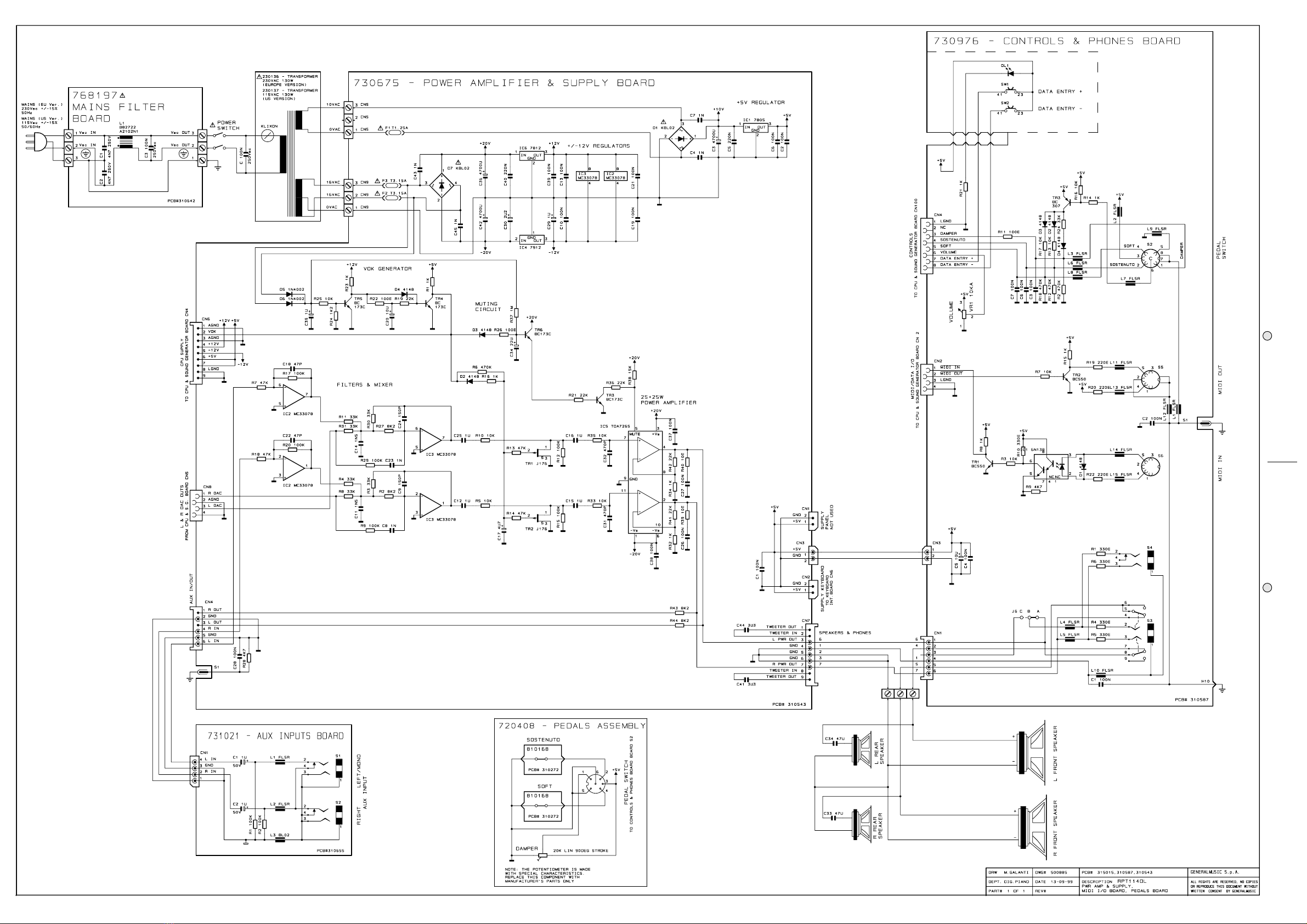
Mains Filter Board
768197 Mains Filter Board (Pcb#310642)
230568 * 10mH 250Vac 1A AC Line EMI Coil “Siemens”
140010 * 3 Contacts P=10 Vert Terminal Block
020493 * 100n 250Vac MKP EMI Capacitor “Siemens”
010545 * 4n7 250V Ceramic Capacitor (Iec-Ul-Csa)
Transformers
230137 Transformer 115Vac 130W (US)
230136 Transformer 230Vac 130W (EU)
Power Amplifier & Supply Board
730675 Power Amplifier & Supply Board (Pcb#310543)
340154 * TO3/TO218 Mica Washer
340079 * TO220 Mica Washer
340078 * TO220 Insulated Bush
141010 * 4 Contacts Vert Female Connector
140917 * 2 Contacts Vert Male Connector
140352 * 9 Contacts Hor Male Connector
140351 * 6 Contacts Hor Male Connector
140010 * 3 Contacts P=10 Vert Terminal Block
110119 * Fuse Clip 10A max (EU) (US)
100958 * TDA7265 Dual 25W Power Amplifier
100919 * MC33078 Dual LN Operational Amplifier
100059 * 7805 +5V 1A Voltage Regulator
100045 * 7812 +12V 1A Voltage Regulator
100043 * 7912 -12V 1A Voltage Regulator
090856 * J176 TO92 P-Channel J-Fet Transistor
090183 * BC550 TO92 LN Npn Transistor
080605 * KBL02 4A 200V Rectifier Diode Bridge
080156 * 1N4002 1A 100V Rectifier Diode
080103 * 1N4148 100mA 75V Signal Diode
Aux Inputs Board Assembly
731022 Aux Inputs Board Assembly
731021 Aux Inputs Board (Pcb#310655)
230569 * FL5R200PNT EMI Coil For Signal
230527 * BL02RN2-R62 EMI Coil For Signal
140872 * 4 Contatcs Hor Male Connector
140217 * Jack Slim Horizontal S-F Socket
210018 1x5mm Adhesive Red Felt (specify mt)
171327 PC-Board Fixing
Controls & Phones Assembly
730693 Controls & Phones Assembly
730976 * Controls & Phones Board (Pcb#310587)
340825 ** 2.8mm Led Spacer
230569 ** FL5R200PNT EMI Coil For Signal
141012 ** 8 Contacts Vert Female Connector
141010 ** 4 Contacts Vert Female Connector
140917 ** 2 Contacts Vert Male Connector
140877 ** Jumper For Contacts Strip (p=2.54mm)
140874 ** Single In Line Vert Male Strip (specify contacts)
140529 ** Microswitch 12V 50mA 0.25mm
140351 ** 6 Contacts Hor Male Connector
140217 ** Jack Slim Horizontal S-F Socket
140216 ** 6 Poles Din Horizontal Female Socket
140212 ** 5 Poles Din Horizontal Female Socket
140207 ** Jack Horizontal F Socket (with dual switch)
100035 ** 6N138 Optocoupler
090194 ** BC560 TO92 LN Pnp Transistor
090183 ** BC550 TO92 LN Npn Transistor
080705 ** Led 3mm 60deg Diffused Red
080103 ** 1N4148 100mA 75V Signal Diode
074699 ** 50K Linear Hor Rotary Potentiometer
660567 * Controls Panel Box
652239 * 2 Keys <<>> Rubber Pad
347360 * Knob
340882 * Button Spacer
110285 * Power Switch
Keyboard Assembly
720563 Keyboard Assembly
840802 * 20 Wires 55cm Length Flat Cable
840795 * 4 Wires 40cm Length Crimp Terminal Cable
761148 * Keyboard Interface Board (Pcb#310577)
141018 ** 20 Contacts Vert Female Connector
141011 ** 6 Contacts Vert Female Connector
140918 ** 2 Contacts Hor Male Connector
140874 ** Single In Line Vert Male Strip (specify contacts)
140872 ** 4 Contatcs Hor Male Connector
104019 ** ST24W02 SOIC 2Kbit Serial Access EEprom
100626 ** 74HC4053 3x2ch Analog Multiplexer
100619 ** 74HC32 Quad 2-Input Or Gate
100610 ** 74HC245 Octal Bus Transceiver
100066 ** LM317 1.2-37V 1.5A Adjustable Regulator
080156 ** 1N4002 1A 100V Rectifier Diode
010726 ** 19.2MHz Ceramic Resonator With Capacitors
010662 ** 220p 10% 50V X8 Cap Array
550645 ** H8-329 Cpu “VALIS” programmed for optical keyboard
140877 ** Jumper For Contacts Strip (p=2.54mm)
720525 * Optical Contacts Assembly
841097 ** 10 Wires 12,5cm Length Flat Cable
841096 ** 4 Wires 7,5cm Length Flat Cable
840823 ** 10 Wires 10cm Length Flat Cable
810561 ** Left Optical Contacts Board (Pcb#310574)
141018 *** 20 Contacts Vert Female Connector
141013 *** 10 Contacts Vert Female Connector
140872 *** 4 Contatcs Hor Male Connector
100919 *** MC33078 Dual LN Operational Amplifier
100626 *** 74HC4053 3x2ch Analog Multiplexer
090153 *** BC327 TO92 Pnp Transistor
080900 *** TCRT5000 Optoelectronic Reflex Sensor
810560 ** Centre Optical Contacts Board (Pcb#310575)
141013 *** 10 Contacts Vert Female Connector
140872 *** 4 Contatcs Hor Male Connector
100919 *** MC33078 Dual LN Operational Amplifier
100626 *** 74HC4053 3x2ch Analog Multiplexer
090153 *** BC327 TO92 Pnp Transistor
080900 *** TCRT5000 Optoelectronic Reflex Sensor
810559 ** Right Optical Contacts Board (Pcb#310576)
141013 *** 10 Contacts Vert Female Connector
140872 *** 4 Contatcs Hor Male Connector
100919 *** MC33078 Dual LN Operational Amplifier
090153 *** BC327 TO92 Pnp Transistor
080900 *** TCRT5000 Optoelectronic Reflex Sensor
660579 ** Optical Contacts Board Support
340093 ** Board Spacer
509016 * Keyboard LEGNICKA Mod. 113/117
508029 * Mechanic DETOA for RPT114
340075 * Nylon Board Spacer
Triple Pedal Assembly
720408 Triple Pedal Assembly
810168 * Reed Switch Board (Pcb#310272)
770717 * Pedals Cable
500063 * Mechanical Parts
340105 ** Plastic Support
171261 ** Chassis Support
170880 ** Screen Panel
170875 ** Right Pedal
170874 ** Left Pedal
170873 ** Centre Pedal
170777 ** Pedal Return Spring
340500 * Potentiometer Lever
340499 * Actuating Lever
340274 * Pedal Rubber
210016 * 1x10mm Adhesive Black Felt (specify mt)
190181 * Pedals Clog
190178 * Permanent Magnet
190015 * Adhesive Rubber Foot
171264 * Lever Washer
171263 * Potentiometer Return Spring
171262 * Potentiometer Support
150066 * Cable Clamping
070556 * 20K Lin (90deg. Stroke) Potentiometer
Speaker Box Assembly
710488 Speaker Box Assembly
770803 * Speaker Box Cables Assembly
220114 * 8ohm 70W 8" Woofer Speaker
210242 * Filler for Speaker Box (Specify m²)
140036 * Screw Block (specify contacts)
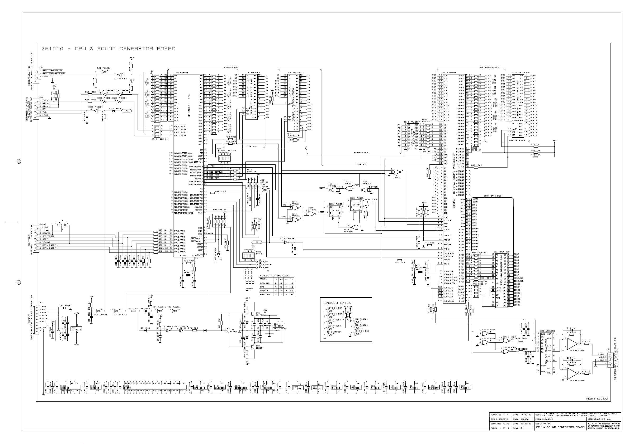
Cpu & Sound Generator Board
761210 Cpu & Sound Generator Board (Pcb#315093/2)
141012 * 8 Contacts Vert Female Connector
141011 * 6 Contacts Vert Female Connector
141010 * 4 Contacts Vert Female Connector
140889 * Dual In Line Vert Male Strip (specify contacts)
140874 * Single In Line Vert Male Strip (specify contacts)
140352 * 9 Contacts Hor Male Connector
106001 * MC33078P SOIC Dual Low Noise Op. Amp.
105009 * DISP3 QFP Digital Sound Processor (Hitachi)
105006 * HD6413003F16 QFP Cpu
104020 * KM62256CLG SOP 256Kbit SRam Ta=55nS
104018 * 23C32000G SOP 32Mbit Rom “Wave”
104010 * HM514280AJ 4M5bit Dram Ta=70nS
103010 * 74HC04D SOIC Hex Inverter
103009 * 74HC02D SOIC Quad 2-In Nor Gate
103007 * 74HC74D SOIC Dual Flip-Flop
103004 * AD1865R SOP 18bit D/A Converter
103000 * 74HC14D Soic Hex Inverter Schmitt Trigger
101501 * 74AC377DW SOIC Octal Dtype Flip Flop
090194 * BC560 TO92 LN Pnp Transistor
090183 * BC550 TO92 LN Npn Transistor
081000 * PMLL4148 Smd 100mA 75V Signal Diode
080241 * 5V6 1W 5% Zener Diode
010727 * 45.1584MHz Quartz Resonator
010704 * 16MHz Quartz Resonator
010599 * 1u 50V -20+80% Ceramic Cap. Multilayer
550607 * 27C1001 1Mbit Program Eprom
140877 * Jumper For Contacts Strip (p=2.54mm)
Wiring Connections
841129 6 Wires 90cm Length Flat Cable
841110 2 Wires 120cm Length Crimp Terminal Cable
841109 8 Wires 120cm Length Flat Cable
841101 2 Wires 90cm Length Crimp Terminal Cable
841098 4 Wires 120cm Length Flat Cable
840901 9 Wires 7.5cm Length Flat Cable
840768 4 Wires 10cm Length Flat Cable
770856 Tweeter Cables Assembly
770855 Speaker Cables Assembly
770801 Mains Cables Assembly
Note:
Each spare part is single quantity unless otherwise specified.
Asterisk prefix explanation:
Omitted = First level spare part.
One asterisk = Second level, part of previous listed first level part.
Two asterisk = Third level, part of previous listed second level part.
Three asterisk = ............
Any request for not above mentioned part must encompass specific
description including:
1) Model name,
2) Section name,
3) Module code,
4) Reference name,
5) Quantity number.