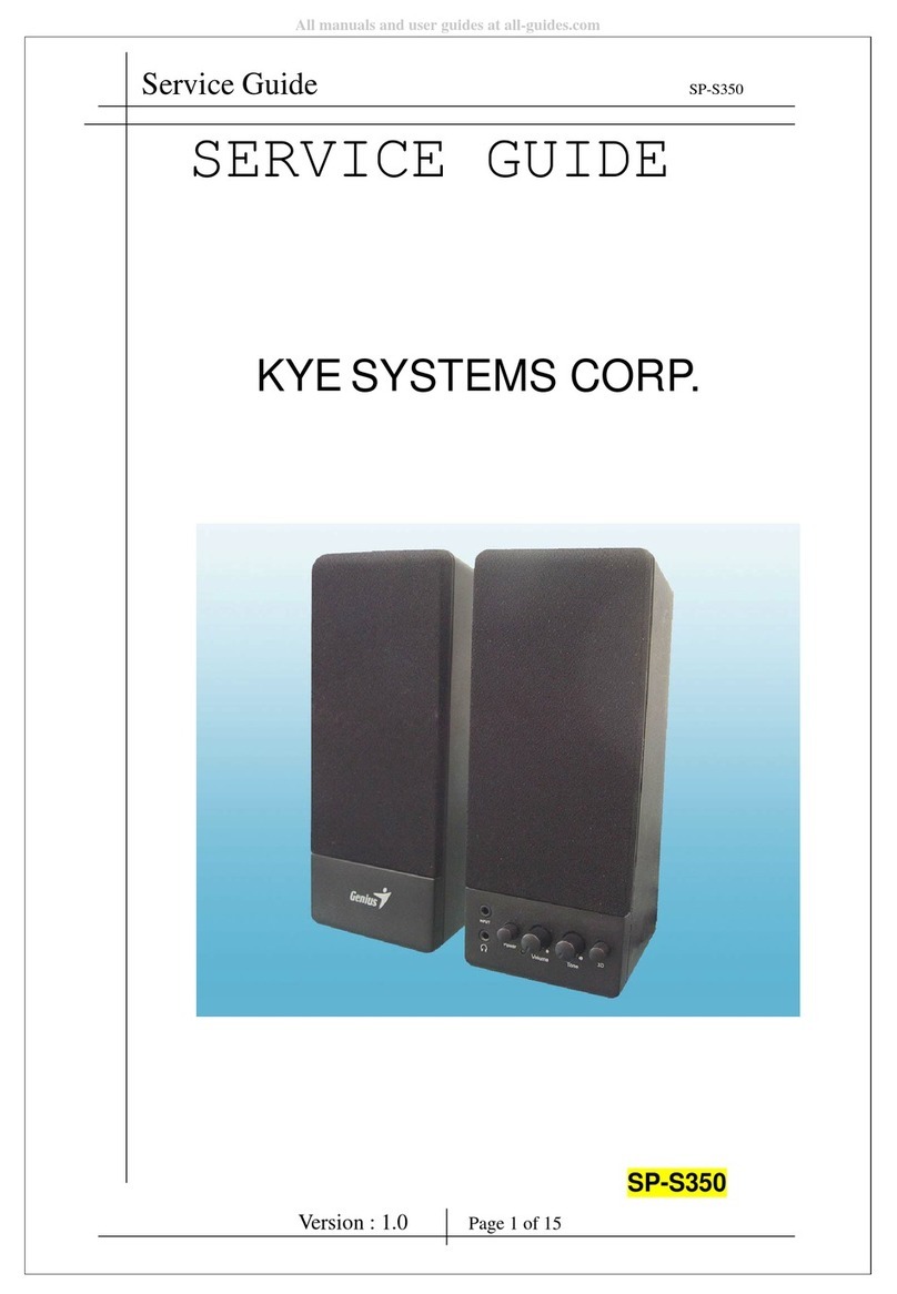
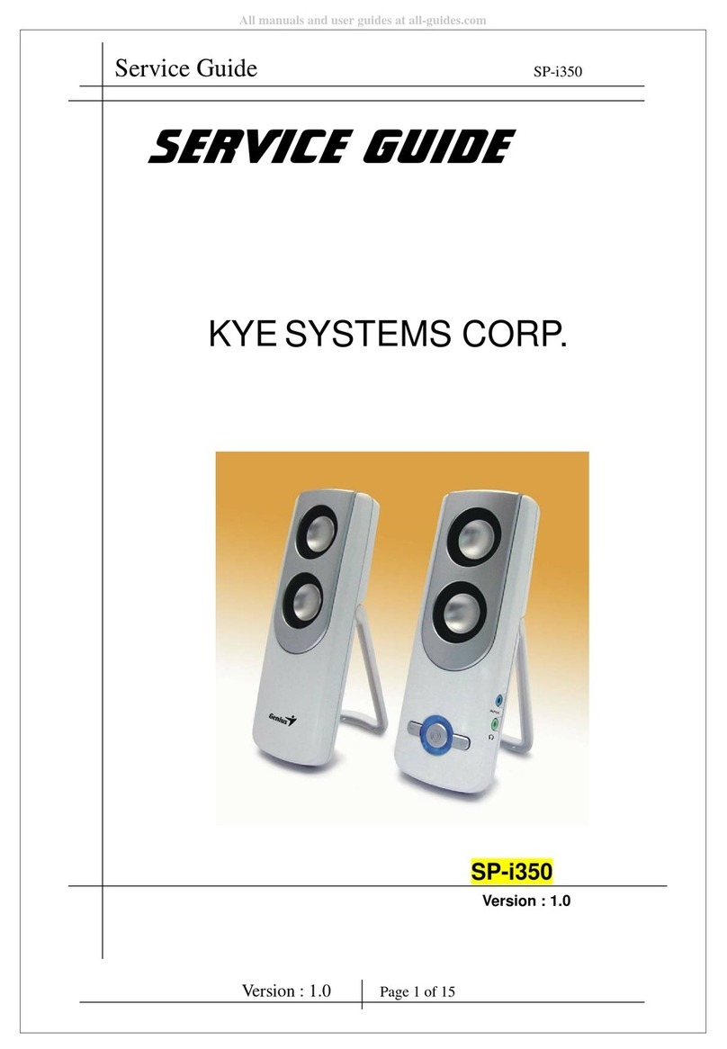
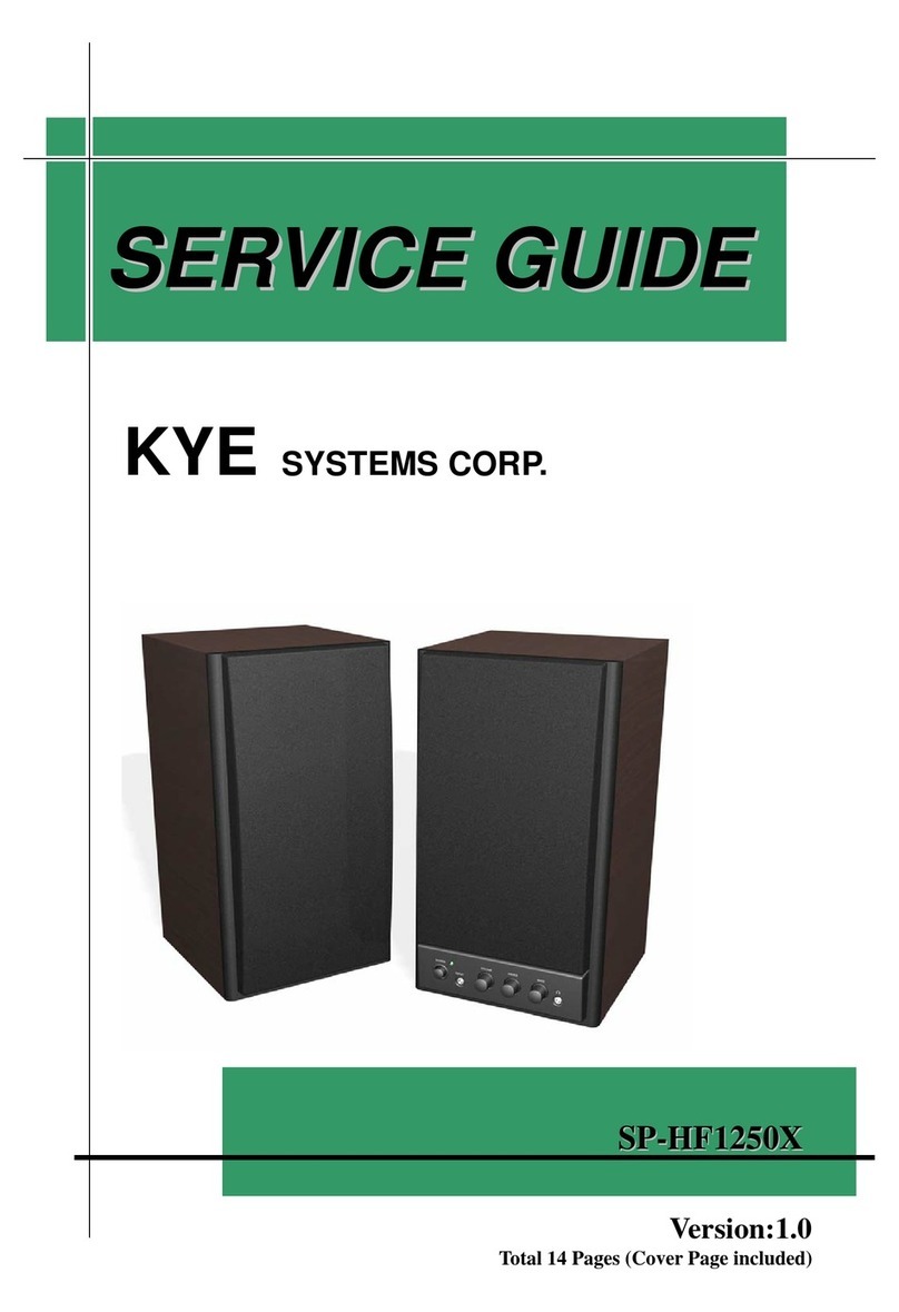
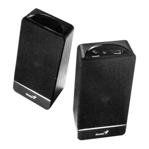
Genius KYE Systems Genius SP-i170 User manual

Service Guide Model No : SP-i170
SERVICE GUIDE
KYESYSTEMS CORP.
Page 1/15
All manuals and user guides at all-guides.com

Service Guide Model No : SP-i170
Revision His ory
Version
Date
Change
1.0
24/08/2010
First Release
Page 2/15
All manuals and user guides at all-guides.com

Service Guide Model No : SP-i170
Table of Con en s
Revision History …………………………………………………………………….2
Ta le of Contents ……………….……………………………………………………3
Getting Started ……………………………………………………………………….4
Conventions Used in this Guide ……………………….…..………………....4
Safety Precautions …….……………………………………………………..4
Chapter 1. How to Handle Defective Returns……………………………………..5
1.1 Speaker no sound
1.2 LED no light
1.3 Power/Volume Kno no function
Chapter 2. Specifications ………………………………………………………….10
Chapter 3. Block Diagram ……………………………………………………….11
Chapter 4. Exploded View …………………………………………………12 & 13
Chapter 5. Part List ………………………………………………………………14
Chapter 6. Schematic Diagram …………………………………………………..15
Chapter 7. Important Notes ………………………………………………………16
7.1 Packing Requirement for Sending the PCB Assem ly y Post …..16
7.2 Short of Spare Parts while Repairing a Speaker System …………16
Page 3/15
All manuals and user guides at all-guides.com

Service Guide Model No : SP-i170
Ge ing S ar ed
Conventions Used in this Guide
Pay Special Attention : Instructions that are important to remem er and
may prevent mistakes .
Caution : Information that, if not followed, may result in damage to the
product .
Safety Precautions
The following precautions should e o served in handling the speaker
Descri ed in this guide :
Place the speakers on a flat, level and sta le surface.
Do not place the speakers in environments su ject to mist, smoke,
vi ration, excessive dust, salty or greasy air, or other corrosive gases
and fumes.
Do not drop or jolt the speakers.
Do not allow anything to drop into the su woofer case through its
ventilator, as it could result in fatal electric shock or fire .
Place the unit far enough from other equipments for good heat
dissipation .
Disconnect the AC power cord from the AC outlet efore performing
any maintenance on the speakers .
Do not perform any maintenance with wet hand .
Prevent foreign su stances, such as water, other liquids or chemicals ,
From entering the speakers while performing maintenance procedures
on the speakers .
Page 4/15
All manuals and user guides at all-guides.com

Service Guide Model No : SP-i170
Chap er 1. How o Handle Defec ive Re urns
Overview
Receiving Defective speakers from
Customers
Function NG
__ __
Analyzing possi le malfunction
causes
Function NG Deciding & proceeding the
rectification methods
Function OK
Replace necessary defective parts
Function OK
Return the speakers with proper
repackaging to customers
Page 5/15
All manuals and user guides at all-guides.com

Service Guide Model No : SP-i170
Pro lems
Item Pro lem Description
1.1 Speaker no sound
1.2 LED no light
1.3 Power/Volume Kno no function
Page 6/15
All manuals and user guides at all-guides.com

Service Guide Model No : SP-i170
Attention
Please follow the num ered sequence marked within parenthesis given in individual Flow
chat, in that this is the est-recommended sequence to rectify the pro lems.
1.1 Speaker no sound (Line in jack no function)
Pro lem
Analyze
and
Identify
Cause
Solution
Speaker no sound
Component cold
solder or Short
Circuit
Defective U1
Speaker ca le disconnect,
J1 defective or speaker
damaged
Check solder
point on PCBA
Check and
Replace defective
IC
Reconnect speaker ca le or
replace defective speaker
driver and component
Page 7/15
All manuals and user guides at all-guides.com

Service Guide Model No : SP-i170
1.2 LED no light
Pro lem
Analyzer and
Identify the Causes
Solutions
Power LED no light
Component cold
solder or Short
Circuit
Defective U2,Q1
or Q2
BT1 or LD1 defective
Check solder
point on PCBA
Check and
Replace defective
IC
or Transistor
Replace defective LED or
Battery
Page 8/15
All manuals and user guides at all-guides.com

Service Guide Model No : SP-i170
1.3 Power/Volume Kno no function
Pro lem
Analyzer and
Identify the Causes
Solution
Bass/Volume no function
Component cold
solder or Short
Circui
t
VR1 efective
Check solder
point on PCBA
Replace defective VR1
Page 9/15
All manuals and user guides at all-guides.com

Service Guide Model No : SP-i170
Chap er 2. Specifica ions
NO.
Descrip ion
Uni
Specifica ions
1
Ou Power a THD 10%
W
≧1.5
2
Sensi ivi y
mV
600± 60
3
Freq. Response (1KHz -3dB)
Hz
70~20K ± 10%
4 S/N ra io
dB
≧
≧≧
≧ 70
5 Hum & Noise (Vol.: max)
mV
≦
≦≦
≦ 2
Page 10/15
All manuals and user guides at all-guides.com

Service Guide Model No : SP-i170
Chap er 3 Block Diagram
Audio in
LCH & RCH
USB In
Power Sw, &
Volume control
Audio
Amplifier IC
PAM8303C
Speaker out
Page 11/15
Battery Charge
All manuals and user guides at all-guides.com

Service Guide Model No : SP-i170
Chap er 4. Exploded View
Page 12/15
All manuals and user guides at all-guides.com

Service Guide Model No : SP-i170
Chap er 5. Par Lis
No
DESCRIPTION
Q y
UNIT
Par No.
1
PAM8303C IC
1 U1
2
LN2054 IC 1 U2
3
BATTERY 1 FBY508037-0003
4
FRONT PANEL 1 BPF500919- 0002
5
CABINET 1 BPQ500402-00AB
6
METAL GRILLE 1 GSN540167-0010
7
FOAM GASKET 1 IVE500021-0004
8
FOAM GASKET 1 IVE500011-0024
9
SPK UNIT 1 FSA510215-140
0
10
WIRE A'SSY
1
ASW501001-021
7
Page 13/15
All manuals and user guides at all-guides.com

Service Guide Model No : SP-i170
Chap er 6. Schema ic Diagram
Pls refer to The Attachment
Page 14/15
All manuals and user guides at all-guides.com

A
B
C
D
D
C
B
ATitle
Number RevisionSize
A4
Date: 24-Aug-2010 Sheet of
File: D:\DocumentsandSettings\liawweilih\桌面\SP I170\SP I170.ddbDrawn By:
USB MONO 2W AMPLIFIER
VER100622
S1
SPK
C9
104
Vcc
C6
10uF
C7
471
C5
1uF
R5
240k
R7
56k
Shut_DN
L1
BEAD120
C1
10uF
C4
104
SP-i170
C13
151
C8
471
R8
56k
R6
240k
C10
270P
C12
270P
C11
270P
R4
100K VDD
B1
IN-
C1
IN+
A1
ShutDN
C2 GND B3
Vo- A3
Vo+ C3
PVDD B2
GND
A2
U1
PAM8303C(BA2010)
So-
So+
L3
BEAD120
L4
BEAD120
C2 473
C3 473
R1 (note)
R2 (note)
L5
BEAD120
L CH
RCH
GND(shield)
GND
USB 5V
R11
10K
CHRG
1
GND
2
BAT 3
PROG 5
Vcc 4
U2
R10
2K
BT1
BATTERY
LN2054
Charge Current(R11) : 10k 100mA
Qiaolin.Ren
TA1
SW_1P1T
VR1A
B50K
C14
105
C15
105
C16
20P
1
2
3
4
5
J1
CN4P-USB
L2
BEAD120
L6
BEAD120
L7
BEAD120
C17
224
Q1
2SC945
Q2
2SC945
R12
330R
LD1
LED-DUAL
R3
330R
Vcc
R9
4.7k
R13
4.7k
AMP IC(PAM8303C): 100R(WPC000170-0001)
NOTE:
AMP IC(BA2010): 2K4 (WPC000170-0002)
WPC000170-0001/2
All manuals and user guides at all-guides.com

Service Guide Model No : SP-i170
Chap er 7. Impor an No es
7.1 Packing Requirement for Sending the PCB Assem ly y Post
PCB assem ly is a kind of sophisticated electronic circuit oard. Well
packing will e required when sending them y post.
* Some sophisticated IC components are mounted on the PCB assem ly,
hence it is necessary to pack each PCB assem ly with a separate static
protecting ag, in order to avoid static electricity.
* Relia le external packing is also very important when sending PCB
assem ly y post, in that it would avoid unnecessarily lost or damage.
7.2 Short of Spare Parts while Repairing a Speaker System
If you are short of spare parts when you have some speaker systems waiting
to e repaired, it would e recommended to take the necessary parts form
one speaker system, so that you may have the as many speaker systems.
Page 15/15
All manuals and user guides at all-guides.com
Table of contents
Other Genius KYE Systems Speakers manuals

Genius KYE Systems
Genius KYE Systems Genius SP-N120 User manual

Genius KYE Systems
Genius KYE Systems SP-F350 User manual

Genius KYE Systems
Genius KYE Systems SP-i350 User manual

Genius KYE Systems
Genius KYE Systems SP-HF1250X User manual

Genius KYE Systems
Genius KYE Systems SP-F120 User manual

Genius KYE Systems
Genius KYE Systems GG00A5 Operating and installation instructions

Genius KYE Systems
Genius KYE Systems SP-S350 User manual