GEOSAT Electronic Eye User manual

INSTALLATION MANUAL

. IM010ES10
Page 2/28
TABLE OF CONTENTS
1. INTRODUCTION ...................................................................................... 3
2. PRECAUTIONS BEFORE INSTALLATION .......................................................... 4
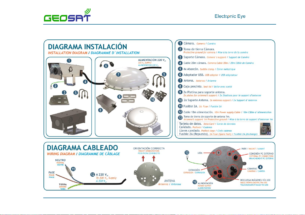
3. INSTALLATION DIAGRAM ........................................................................... 5
4. ANTENNA AND CAMERA INSTALLATION ......................................................... 6
5. CABLE INSTALLATION .............................................................................. 8
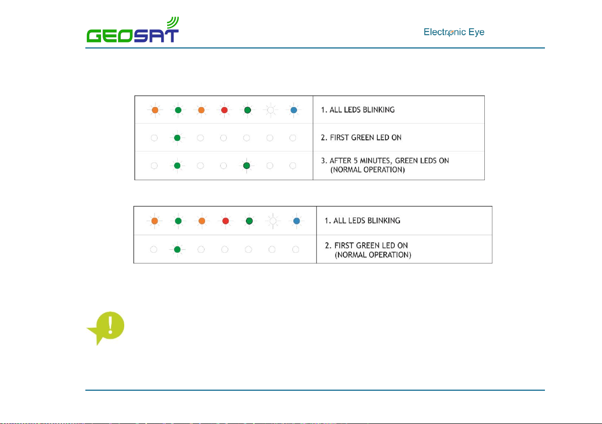
5.1. LED legend ....................................................................................................8
5.2. Cable connection ............................................................................................9
5.3. External Sensor ............................................................................................ 11
6. WEB CONFIGURATION ............................................................................ 12
6.1. Access passwords .......................................................................................... 12
6.2. Web access ................................................................................................. 13
6.3. Electronic Eye configuration ............................................................................ 15
7. SETTING THE CAMERA ANGLE................................................................... 20
8. CORRECT OPERATION VERIFICATION .......................................................... 23
9. LED STATUS ........................................................................................ 25
10. CHARACTERISTICS ............................................................................... 26

. IM010ES10
Page 3/28
1. INTRODUCTION
Electronic Eye is a remote electronic
monitoring system with automatic HD still
image capture for the control of bycatch and
other illegal activities.
All activities during fishing operations are
registered in tamper-proof images with
embedded GPS position, date and time.
With the help of these images, the observer
can analyse and distinguish species, estimate
fishing quota and verify the fishing
operations used during the trip.
The Electronic Eye is a fully integrated and stand-alone system:
No installation needed at the bridge.
No need of additional equipment.
Just needs to be connected to the power supply.

. IM010ES10
Page 4/28
2. PRECAUTIONS BEFORE INSTALLATION
To ensure that the Electronic Eye works effectively, follow all the steps in the installation manual.
Checking the operation of the equipment
You must have a computer or a mobile phone with Wi-Fi to verify proper operation of the
system. Apple devices are not supported.
Antenna orientation
The part of the antenna with connectors must be facing down.
DC power for Electronic Eye
In the Electronic Eye with 24Vdc cable, this cable should not be short-circuited in any case.
Check with Marine Instruments for DC power.
Magnetic switch to turn on batteries
People with pacemakers should not handle the equipment unless they are sure
that the pacemaker will not be affected by the magnetic field.

. IM010ES10
Page 5/28
3. INSTALLATION DIAGRAM

. IM010ES10
Page 6/28
4. ANTENNA AND CAMERA INSTALLATION
STEP 1. Select a clear area with good GPS coverage for the installation of the device.
STEP 2. Place the antenna supports in the antenna.
STEP 3. Fix the antenna. In order to do this, use the U-bolts and the bracket supplied with the
equipment.
THE ANTENNA MUST BE INSTALLED WITH ALL CONNECTORS FACING DOWN. See
document DI007 “Installation Diagram”.
Otherwise, the equipment might not work properly.

. IM010ES10
Page 7/28
STEP 4. Connect the base of the antenna to the ground. Use the material provided by Marine
Instruments.
STEP 5. Fix the camera support to the vessel rail, using the U-bolts and the supplied nuts and
bolts. Connect the support to the ground.
STEP 6. Fix the camera on the support and adjust to the required angle. In order to do so you
must:
Unscrew the nuts at the top to remove the camera viewer.
To fix the angle, slightly adjust the screws on both sides.
With the position set, tighten the screws on both sides and fix the camera viewer in place.
STEP 7. Once the antenna and cameras are set, connect the power supply cable to the
device (please see “Cable installation” section).

. IM010ES10
Page 8/28
5. CABLE INSTALLATION
5.1. LED legend

. IM010ES10
Page 9/28
5.2. Cable connection
STEP 1. Connect the camera cables to the base unit.
Up to three cameras can be connected to every base unit. Camera connectors are
marked with: “CAM1”, CAM2” and “CAM3”.
STEP 2. Remove the magnet and check that all the LEDs are on (see image). After checking,
place it back.
STEP 3. Connect one end of the cable to the antenna and the other to the vessel AC power
supply. Wait until all LEDs are on and then remove the magnet for good.
Power connectors are marked with: “PWR”.
A fuse must be inserted in the phase AC wire.

. IM010ES10
Page 10/28
STEP 4. Verify the following sequence:
a. For equipment installed outdoors, the sequence will be as follows:
b. For systems installed indoors:
STEP 5. Fix the seal box.
Once the seal box is installed, close and place the supplied padlock.

. IM010ES10
Page 11/28
5.3. External Sensor
In the expansion connector it is possible to connect an external sensor:
Closed contact Sensor.
PNP Sensor.
An analogic sensor can also be connected.
The connection for these sensors are labelled as “EXP”.
Both for installing an external sensor or an analogic sensor, please, contact Marine
Instruments.

. IM010ES10
Page 12/28
6. WEB CONFIGURATION
6.1. Access passwords
The installer will need the following passwords:
For Electronic Eye Wi-Fi connection: WIFI name and WIFI PASSWORD on the card and the key
holder card supplied with the equipment.
For web configuration of Electronic Eye:
Web address: WEB ACCESS on the card or the key holder card supplied with the
equipment.
User name and password: User name and password for the installer must be
requested by email to Marine Instruments.

. IM010ES10
Page 13/28
The user and password of the key holder card supplied with the equipment are
exclusively for the observer.
For web access, we recommend Google Chrome o Mozilla Firefox browsers. It is
recommended not to use Internet Explorer.
6.2. Web access
To configure the equipment and start working with Electronic Eye, follow these steps:
STEP 1. Once the equipment is on, the Wi-Fi spot with the name of the Electronic Eye will
appear. Click on it and then click Connect and enter the password provided (WIFI in the key
holder card supplied with the equipment).
STEP 2. Open an Internet browser (Recommended Google Chrome or Mozilla Firefox) and
type in the IP address included in the key holder card.
STEP 3. Type in the user name and password provided by email.

. IM010ES10
Page 14/28
Remember that you must request the user name and password of the installer to
configure the equipment. In order to do this, contact your distributor or Marine
Instruments.
STEP 4. In the home page, the following options appear:
STEP 5. Click on “Configure cameras”.
Current view os the cameras in the web. See section
“Camera position”.
Shows the information of the last image taken.
Access to the Electronic Eye configuration.

. IM010ES10
Page 15/28
6.3. Electronic Eye configuration
In the section “Configure camera” the following configuration criteria appear:
Name of the vessel. Only letters (except ñ) and numbers.
Should not use blank spaces or special symbols.
Same name for all the Electronic Eye on board.
WI-FI transmission channel used by Electronic Eye
Camera auto-focus
Type of camera definition: outside use with satellite transmission and GPS
coverage (master), outside use without satellite transmission or GPS
coverage (slave) or inside use without satellite transmission or GPS
coverage (hold)
Fast camera trigger: Threshold speed or external sensor (in conveyor belts,
winch, cranes…)

. IM010ES10
Page 16/28
Threshold speed under which the system will start the fishing mode.
Maximum duration of fishing mode.
Trigger frequency during fishing mode.
Trigger frequency when the system is not on fishing mode.
Number of pictures taken after the last sensor signal.
Time taking pictures after 220V power cut.
Transmission interval of GPS position via satellite.

. IM010ES10
Page 17/28
Modes of operation
The system can be configured for outside use with satellite transmission (master), outside use
without satellite transmission (slave) or for inside use (hold). The features of each one of them are
as follows:
OUTSIDE USE WITH SATELLITE TRANSMISSION [MASTER]. Electronic Eye installed on the
outside of the vessel and configured in this way, have GPS coverage and transmits via
Iridium every hour by default, the following parameters: latitude, longitude, last photo
number and some configuration parameters.
OUTSIDE USE WITHOUT SATELLITE TRANSMISSION [SLAVE]. Electronic Eye installed on the
outside of the vessel and configured in this way, have GPS coverage but DO NOT transmit
data via Iridium.
INSIDE USE. This configuration applies to Electronic Eye installed inside the vessel. These do
NOT have GPS coverage and do NOT have Iridium satellite transmission.
For outdoor installations, please contact Marine Instruments.

. IM010ES10
Page 18/28
Configuration settings
To configure the settings of the camera follow these steps:
1
2
3
4
5
6
7

. IM010ES10
Page 19/28
(1) Type in the name of the vessel (only numbers and letters).
(2) Select the copy mode to external device: “Copy all to fill external USB memory”.
(3) Select the camera mode of operation:
a. Outside use (Master): select “Deck master tracking camera”.
b. Outside use (Slave): select “Deck slave camera”.
c. Inside use (Hold): “Camera under deck”.
It’s necessary to select UTC Date. Set time in the UTC Date field for the images to
have a real date associated to them.
(4) Set the camera trigger on Both.
(5) Select time intervals between images according to: camera trigger (speed or sensor), duration
of the camera trigger modes, number of photos after sensor activation and time taking photos
after power cut.
Camera configurations can be different.
(6) Time between GPS position messages transmitted through Iridium satellite (only for Master).
(7) Click on “Change configuration” to save changes.
Images will be saved automatically after clicking on “Exit”.

. IM010ES10
Page 20/28
7. SETTING THE CAMERA ANGLE
STEP 1. Access Wi-Fi spot of the Electronic Eye we want to set the camera angle. Click on
connect and type in the password supplied (PW WIFI in the key card holder).
STEP 2. Open an Internet web browser (Recommended Google Chrome or Mozilla Firefox)
and type in the IP address included in the key card holder.
STEP 3. Type in the user and password provided by email.
User name and password for the installer must be requested by email to configure the
system. To do that, please contact your distributor or Marine Instruments.
User and password of the key card holder can only be used by the observer.
STEP 4. To check the camera is pointing at the right angle, click on “Current view Camera”.
In this screen, the current view of the images is shown, so that the user can change the
angle of the camera and adjust it on the spot.
Table of contents