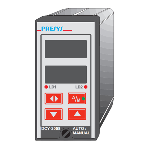
Presys DMY-2011 User manual

DMY-2011 / 2035 / 2036 Universal Process Indicators
PRESYS
LD1 LD2
DMY-2035
ACK
LD1
LD2
DMY-2036
PRESYS
LD1 LD2
PRESYS
DMY-2011
ACKA C K
ACK
ACK
PRESYS
TECHNICAL MANUAL
Instruments
presys

PRESYS | Instruments DMY-2011, DMY-2035 and DMY-2036
EM0141-00
TABLE OF CONTENTS
Page
1 - Introduction......................................................................................... 1
1.1 - Description...................................................................................... 1
1.2 - Order Code..................................................................................... 3
1.3 - Technical Specifications.................................................................. 5
2 - Installation........................................................................................... 7
2.1 - Mechanical Installation.................................................................... 7
2.2 - Electrical Installation........................................................................ 8
2.3 - Process Input Signal Connection..................................................... 9
2.3.1 - Thermocouple Input.................................................................. 10
2.3.2 - RTD Input.................................................................................. 11
2.3.3 - Milliampere Input....................................................................... 12
2.3.4 - Volt or Millivolt Input.................................................................. 13
2.4 - Output Signal Connections.............................................................. 14
2.5 - Connection Diagram........................................................................ 16
2.6 - Communication............................................................................... 18
2.7 - Engineering Units............................................................................ 18
3 - Operation............................................................................................. 19
3.1 - Normal Operation............................................................................ 19
3.2 -Configuration.................................................................................... 19
4 - Maintenance........................................................................................ 31
4.1 - Indicator Hardware.......................................................................... 31
4.2 - Hardware Configuration................................................................... 32
4.3 - Snubber Use for Relay.................................................................... 33
4.4 - Optional Module Connection........................................................... 34
4.5 - Calibration....................................................................................... 37
4.6 - Hardware Maintenance Instructions................................................ 42
4.7 - List of components.......................................................................... 44
4.8 - List of recommended spare components......................................... 47
presys

PRESYS | Instruments DMY-2011, DMY-2035 and DMY-2036
Introduction
Page 1
1 - Introduction
1.1 - Description
PRESYS DMY-2011, 2035 and 2036 Indicators are microprocessor-based
instruments that show all kind of industrial process variable, such as: temperature,
pressure, flow and level. They have non-volatile internal memory (E2PROM) to store
calibration values. Their high accuracy is warranted by autocalibration techniques
based on high thermal stability voltage reference.
They can communicate with computers by optional communication module
RS-232 or RS-422/485.
The Indicators are able to monitor two universal standard inputs and accept
direct connection of thermocouples, RTD, current (mAdc) and voltage (mVdc, Vdc).
Thermocouples and RTD inputs are linearized automatically by tables stored in
EPROM memory. A 24Vdc voltage source isolated from output and with short-circuit
protection is provided for transmitter power supply.
The type of input selected by the user is enabled by jumpers and by the
software configuration. All configuration data can be protected by a password system
and are stored in the non-volatile memory in case of power failure.
According to modularity design concept, the instruments accept up to four
output modules. The type of outputs are: retransmittion, SPDT relay, SPST relay and
solid state relay. The outputs are isolated from the inputs.
They accept 90 to 240VAC or 130 to 340VDC (with any polarity) power supply.
The equipments have extruded aluminum case which avoids electrical noise,
electromagnetic interference, radiofrequency interference, etc. and their robust
construction makes them tough enough for the most hostile environments.
Figure 1 - DMY - 2011 Indicator front panel
presys

PRESYS | Instruments DMY-2011, DMY-2035 and DMY-2036
Introduction
Page 2
ENTER
UP KEY
DOWN KEY
(3)
(2)
(4)
(1)
(4)
A
CKNOWLEDGE
PRESYS
DMY-2035
A
CKNOWLEDGE
UP KEY
DOWN KEY
SCREW FOR INDICATOR
INSERTION IN / REMOVAL FROM CASE
ENTER
(1)
PLACE FOR STICKING THE
ENGINEERING UNITS
(2) CHANNEL 1 PROCESS
VARIABLE DISPLAY
(3) CHANNEL 2 PROCESS
VARIABLE DISPLAY
(4)
CONFIGURABLE
SIGNALING LEDS
Figure 2 - DMY-2035 and DMY-2036 Indicators front panels
On the front panel of the instruments there are two displays configurable up to
four high visibility digits which show the process variables of channel 1 (upper
display) and channel 2 (lower display). During configuration, the display shows
mnemonics and parameter values. The leds and the display can be used as a visual
indication of alarm or they can be associated with the alarm outputs. So, there are up
to seven alarm indications available (four alarm modules together with the display
and leds). The alarm outputs can be configured, independently, to operate with latch,
demanding the operator acknowledgement by means of the front panel keys in order
to deactivate them after the process variable returns to normal condition.
Up to two rettransmitter outputs are available to provide a linear output signal
from 4 to 20 mA, 1 to 5V or 0 to 10V proportional to the input process variable being
measured. This signal allows the retransmissions of the variables to a distant
location. When using only one analog output, up to three alarm modules can be
used, and when using two analog outputs, up to two alarm modules can be used.
presys

PRESYS | Instruments DMY-2011, DMY-2035 and DMY-2036
Introduction
Page 3
1.2 - Order code
Order Code
DMY - 2011 / 2035 / 2036 - - - - - - -
A B C D E F G
Field A Output 1
0 Not used
1 4 to 20mA
2 1 to 5V
3 0 to 10V
4 SPST relay
5 Open collector voltage
6 Solid state relay
Field B Output 2
Same code of Output 1
Field C Output 3
0 Not used
1 SPDT relay
2 Open collector voltage
3 Solid state relay
Field D Output 4
Same code of Output 3
Field E Power supply
1 90 to 240VAC or 130 to 340VDC (any polarity)
2 24VDC
3 12VDC
Field F Communication
0 Not used
1 RS-232
2 RS-485
3 RS-422
Field G Case Protection Grade
0 General usage, protected place
1 Front aspersion-proof
2 Weather-proof
presys

PRESYS | Instruments DMY-2011, DMY-2035 and DMY-2036
Introduction
Page 4
Note 1 - Ranges and input types, indication, relay usage as alarms and alarm
setpoints are, among other things, items that the user can program through the front
panel keys (if wanted, specify such information so that all the configuration can be
made by PRESYS).
Note 2 - Other hardware and software features can be available under previous
consult.
Code example:
1) DMY - 2011 - 0 - 0 - 1 - 1 - 1 - 0 - 0
This code defines a DMY-2011 Indicator with two SPDT relays which can be
used as high and low alarms, 90 to 240VAC or 130 to 340VDC electric power supply,
protected field usage.
presys

PRESYS | Instruments DMY-2011, DMY-2035 and DMY-2036
Introduction
Page 5
1.3 - Specifications
Inputs:
•Two inputs configurable for thermocouple (J, K, T, E, R, S, under ITS-90),
Pt-100 RTD under DIN 43760, 4 to 20mA, 0 to 55mVDC, 1 to 5VDC and
0 to 10VDC. Input impedance of 250Ωfor mA, 10MΩfor 5VDC and 2MΩabove
5VDC. Table 1 shows the temperature ranges for thermocouples and RTD and
the resolution for linear input sensors.
Input Sensor Measuring Range Limits
Thermocouple lower limit
°F
higher limit
°F
lower limit
°C
higher limit
°C
Type J -184 1886.0 -120 1030.0
Type K -346 2498 -210 1370
Type T -418 752 -250 400
Type E -148.0 1436.0 -100.0 780.0
Type R -58 3200 -50 1760
Type S -58 3200 -50 1760
RTD
2 or 3-wire Pt-100
-346.0
1256.0
-210.0
680.0*
Linear
Range
Resolution
Voltage 0 to 55mV 6µV
0 to 5V 500µV
0 to 10V 1mV
Current 0 to 20mA 2µA
(*)including wire resistance
Table 1 - Measuring ranges for input sensors
Outputs:
•4 to 20 mA, 1 to 5 Vdc, 0 to 10 Vdc Analog Retransmitter, with connection for
up to two optional modules galvanically isolated of 300Vac from power supply
and inputs.
•SPDT relay for alarm rated for 3A at 220Vac, or 10A at 220Vac under order.
In this case alarm module is not connected, but soldered to the board.
Connection for up to four modules (using both analog output connectors). In
case of using one analog output, one can use three alarm modules, or
whenever one uses two analog outputs, it is possible to have up to two alarm
modules.
•Logic signal, open collector transistor, 24 Vdc, 40 mA maximum with isolation.
•Solid state relay rated for 2A at 250Vac with isolation.
presys

PRESYS | Instruments DMY-2011, DMY-2035 and DMY-2036
Introduction
Page 6
Serial Communication:
RS-232 or RS-422/485, 50 Vdc isolation, optional module connected to the
CPU Board.
Indication:
Two red display sets with four digits, configured with decimal point.
Configuration:
By front-panel pushbuttons and internal jumpers.
Sampling rate:
120 ms for input indication in -999 to 9999 range. The display is updated each
second.
Accuracy:
±0.1 % of full scale for TC, RTD, mA, mV, Vdc input.
±0.5 % of full scale for analog retransmitter output, 750 Ωmaximum load.
Linearization:
±0.1 °C for RTD and ±0.2 °C for TC.
Square root extraction:
±0.5 % of reading, for input above 10 % of span. 0 to 5 % of programmable
Cut-off.
Cold junction compensation:
±2.0 °C in the range from 0 to 50°C ambient temperature.
Thermal stability:
±0.005 % / °C of span referred to ambient temperature of 25°C
Power supply:
90 to 240VAC or 130 to 340VDC (any polarity), 10W nominal; 24VDC, 12VDC
and other values are optional.
2-wire transmitter power supply:
24VDC voltage and 50mA maximum, isolated from output, short-circuit
protection.
Operating ambient:
to 50 °C temperature and 90 % maximum relative humidity.
Dimensions:
2011 1/4 DIN (96 ×96 mm) with 162 mm depth.
Panel cut of 92 ×92 mm.
2035/2036 1/8 DIN (48 ×96 mm) with 162 mm depth.
Panel cut of 45 ×92 mm.
Weight:
0.5 kg approx (DMY-2035/36) / 0.6 kg nominal (DMY-2011).
Warranty:
One-year warranty.
presys

PRESYS | Instruments DMY-2011, DMY-2035 and DMY-2036
Installation
Page 7
2 - Installation
2.1 - Mechanical Installation
The front panel of the DMY - 2035 / 2036 Indicators has 1/8 DIN size
(48 ×96 mm) and the front panel of the DMY - 2011 Indicator has 1/4 DIN size
(96 ×96 mm).
The Indicators are fixed by the rails which press them against the back side of
the panel.
After preparing a 45 ×92 mm cut in the panel for DMY - 2035 / 2036 or a
92 ×92 mm cut for DMY - 2011, remove the rails from the Indicator and slide its rear
through the cut until its front reaches the panel. Place the rails again in the Indicator
from the back of the panel and tighten the screws as shown in figures 3 and 4.
Figure 3 - Dimensional drawing, panel mounting cutout and side view
for DMY-2035/2036 Indicators
presys

PRESYS | Instruments DMY-2011, DMY-2035 and DMY-2036
Installation
Page 8
Attachment screw
W
arning: follow indicated directions
when mounting rails..
Figure 4 - Dimensional drawing, panel mounting cutout and side view
for DMY-2011 Indicator
2.2 - Electrical Installation
DMY - 2011, 2035 and 2036 Indicators may be powered by voltage between
90 and 240VAC or 130 to 340VDC, any polarity. Remember that the internal circuit is
powered whenever the instrument is connected to the mains.
Input and output signals must be connected to the instrument only when it is
turned off.
Figure 5 shows the instrument rear terminals for connection to power supply,
ground, communication, process input and output signals.
Signal wiring must be kept far away from power wires.
Due to its metal case the instrument ground should be connected to earth
ground. Never connect the ground to neutral terminal.
presys

PRESYS | Instruments DMY-2011, DMY-2035 and DMY-2036
Installation
Page 9
Figure 5 - Indicator Terminals
2.3 - Process Input Signal Connections.
The Indicators accept the connection of thermocouple, 2 or 3-wire RTD, mA,
mV or V. See the different types and ranges of input sensors in table 1, section 1.3
on Technical Specifications.
The input sensor is enabled by internal jumpers (see section 4.2 on Hardware
Configuration) and by selection of the sensor in the software (see section 3.2 on
Configuration). The connections explained below will have the desired result only if
the instrument is correctly configured by software and hardware.
presys

PRESYS | Instruments DMY-2011, DMY-2035 and DMY-2036
Installation
Page 10
The connection of a certain type of sensor in input 1 does not restrict the use
of other sensor in input 2.
In order to avoid noise in the wiring, use twisted pair cable and cross sensor
connection wire inside a metallic tube or use shielded cable. Make sure to connect
only one shield wire end either to board terminal or to sensor ground, as shown in the
next items.
WARNING: GROUNDING TWO SHIELD WIRE ENDS MAY CAUSE NOISE IN THE
INDICATOR.
2.3.1 - Thermocouple Input
When using only one thermocouple, connect it to input 1, in order to get a
better precision in the temperature measurement, since the cold junction sensor is
placed near input 1.
In order to reduce the error due to cold junction compensation, use thermal
paste in the rear, at the terminals where the thermocouple is connected to the cold
junction sensor.
Connect the thermocouple to terminals 2 (+) and 3 (-) to use input 1 or to
terminals 5 (+) and 6 (-) to use input 2 as shown in figure 6.
Use appropriate compensating cables with the same material of the
thermocouple in order to connect it to the instrument. Check if the thermocouple
polarity is equal to those of the terminals.
654321
654321
-+ -+
-+ -+
Grounded Ungrounded
Thermocouple
Note 1
Note 1
Twisted or
shielded pair
Channel 2 Channel 1 Channel 2 Channel 1
Note 1: Keep shielded wire disconnected at this end.
Figure 6 - Thermocouple Input
presys

PRESYS | Instruments DMY-2011, DMY-2035 and DMY-2036
Installation
Page 11
2.3.2 - RTD Input
An RTD input device may be a 2-wire, 3-wire or 4-wire RTD. All types of
connection are shown in figure 7.
A 2-wire RTD is connected to terminals 1 and 3 when using input 1 and to
terminals 4 and 6 when using input 2 as shown in figure 7.
A 3-wire RTD is connected in the same way as explained for a 2-wire RTD,
adding the connection of the compensation wire to terminal 2 for input 1 and to
terminal 5 for input 2 as shown in figure 7.
Connect a 4-wire RTD as indicated for a 3-wire RTD and keep its forth wire
disconnected. See figure 7.
With a 3-wire RTD one gets a better precision than with a 2-wire RTD.
Use wires of same material, gauge and length on all 3 terminals of each
channel for compensating resistance. The maximum resistance of each connection
wire must be 10 Ω. Use 18 AWG wire (minimum) for distances up to 50 m and 16
AWG for distances greater than 50 m.
654321
654321
654321
654321
654321
654321
GROUNDED
UNGROUNDED
2-WIRE 3-WIRE 4-WIRE
Channel 2 Channel 1 Channel 2 Channel 1 Channel 2 Channel 1
Channel 2 Channel 1
Channel 2 Channel 1 Channel 2 Chanhel 1
Note 1: Shield to be left unconnected at this end..
Note 1 Note 1 Note 1 Note 1
Note
1
Note 1
Note 1
Note 1
RTD
RTD RTD RTD
RTD RTD
NC NC
NC NC
Figure 7 - RTD Input
presys

PRESYS | Instruments DMY-2011, DMY-2035 and DMY-2036
Installation
Page 12
2.3.3 - Milliampere Input
A current source of 4 to 20 mA can be applied to terminals 1(+) and 3(-) for
input 1 and to terminals 4(+) and 6(-) for input 2. The current signal can be generated
by a transmitter with an external power supply. In case of using the 24 VDC internal
voltage source from the Indicator to power a two-wire transmitter, the current is
received only by terminal 1(+) for input 1 and by terminal 4(+) for input 2. Figure 8
shows both possibilities of connection.
Figure 8 - Milliampere Input
presys

PRESYS | Instruments DMY-2011, DMY-2035 and DMY-2036
Installation
Page 13
2.3.4 - Volt or Millivolt Input
0 to 55 mVDC or to 0 to 5 VDC must be applied to terminals 2 (+) and 3 (-) for
input 1 and to terminals 5(+) and 6(-) for input 2. 0 to 10 VDC must be applied to
terminals 1(+) and 3(-) for input 1 and to terminals 4(+) and 6(-) for input 2. The
connections are shown in figure 9.
Figure 9 - Volt or millivolt Input
presys

PRESYS | Instruments DMY-2011, DMY-2035 and DMY-2036
Installation
Page 14
2.4 - Output Signal Connections
The Indicator can have up to four output signals: output 1, output 2, output 3
and output 4. Outputs 1 and 2 are used as retransmitter or alarm outputs. Outputs 3
and 4 are used only as alarm outputs.
For outputs 1 and 2, there are six different types of outputs available:
retransmitter (4 to 20mA, 0 to 5Vdc or 0 to 10Vdc), SPST relay, open collector
voltage and solid state relay.
For outputs 3 and 4, there are three different types of outputs: SPDT relay,
open collector voltage and solid state relay. Figure 10 shows the Indicator output
types.
presys

PRESYS | Instruments DMY-2011, DMY-2035 and DMY-2036
Installation
Page 15
Note that the output terminals will present the corresponding signals
only if the optional modules are installed and the output is correctly
configured. For analog outputs, refer to section 3.2 on Configuration and
section 4.3 on Optional Module Connection for details on installation and
configuration of optional modules.
(*) Relay contact states shown are valid for SAFE option selected (see section 3.2 on Configuration), instrument
powered on and non-alarm condition. Positions of the contacts are changed in alarm condition (with SAFE option
selected) or when the instrument is turned off.
Figure 10 - Output Connection
presys

PRESYS | Instruments DMY-2011, DMY-2035 and DMY-2036
Installation
Page 16
2.5 - Connection Diagrams
presys

PRESYS | Instruments DMY-2011, DMY-2035 and DMY-2036
Installation
Page 17
presys

PRESYS | Instruments DMY-2011, DMY-2035 and DMY-2036
Installation
Page 18
2.6 - Communication
DMY - 2011, 2035 and 2036 Indicators can communicate with computers
through RS-232 or RS-422/485 using MODBUS protocol communication software,
when the optional communication module is installed and the communication
parameters are configured.
Specific information on communication and signal connection is described in
the communication manual.
2.7 - Engineering Units
A label with several Engineering Units is supplied with each Indicator. Select
the one corresponding to the variable shown on the display and stick it to the front
panel of the Indicator.
presys
This manual suits for next models
2
Table of contents
Other Presys Measuring Instrument manuals

Presys
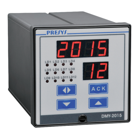
Presys DMY-2015 User manual

Presys
Presys DMY-2030-F User manual

Presys
Presys PROFI BUS DMY-2015-PB User manual

Presys
Presys TA-25NL User manual

Presys
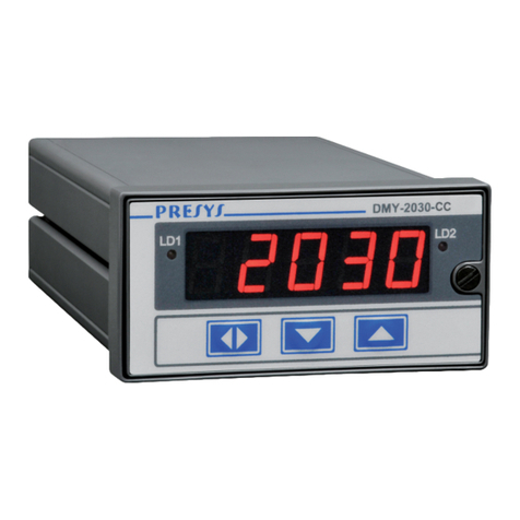
Presys DMY-2030-CC User manual

Presys
Presys DMY-2030 Light User manual

Presys
Presys DMY-2030 Light User manual

Presys
Presys DMY-2030 Light User manual

Presys
Presys DCY-2058 User manual

Presys
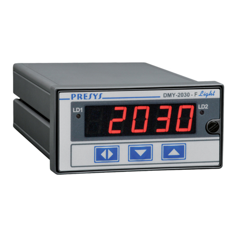
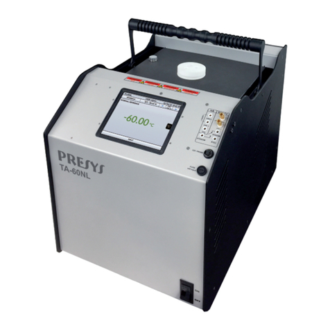
Presys TA-60NL User manual