55
3.0 Application – user instruction
The HVU may not be in operation for longer periods of
time (more than 45 min.) without opening the connec-
tions in the Channel Duct System, since otherwise the
pump will superheat and break down. Optionally, use
the built-in start/stop function.
Use
When you are finished using the unit, keep the flap open
in 1-5 seconds so that the particles are sucked away
from the vertical pipe, so that it does not fall into the
head of the operator, the next time the system is in use.
4.0 Maintenance
At least once annually, the whole point suction plant
should be overhauled by an authorised serviceman.
Periodic maintenance:
• All electric parts should be checked annually.
• In principle, the vacuum pump/engine is main-
tenance-free due to the factory-mounted com-
pletely closed special ball bearings, which do
not require any maintenance. Exchange of worn
bearings should only be carried out by an elec-
tro-company.
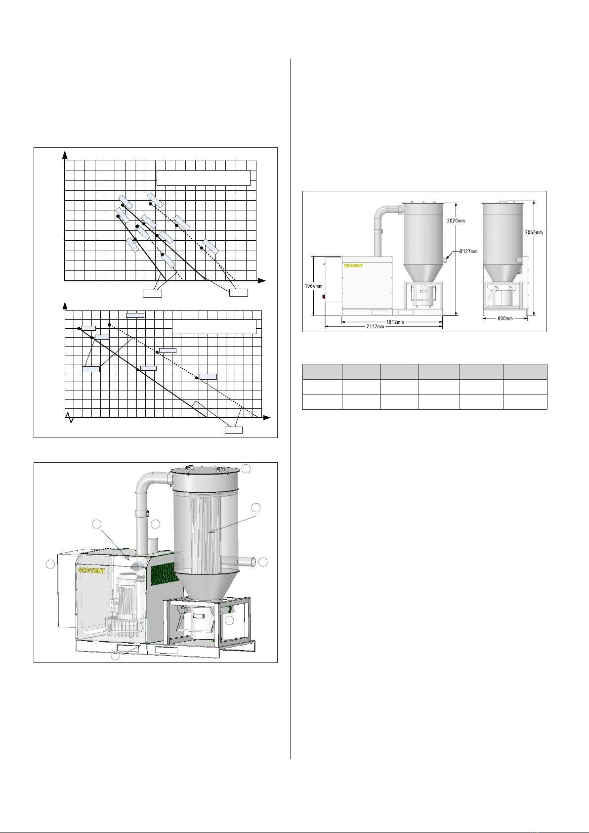
4.1 Exchange of filter medium
The collection bucket should be emptied when approx.
two thirds of it is full, since otherwise it may further load
the filter medium. The filter medium should be exchan-
ged after approx. 4,000-8,000 hours of operation or max.
4 years. Partly, this depends on the load on the filter, for
example whether it has been used in connection with
welding or grinding, etc.
Procedure:
1. Disconnect the Unit on the repair switch. Please en-
sure that the switch cannot be activated during the
service operation.
2. Disconnect/dismantle the compressed air connecti-
on.
3. Before dismantling the dusty filter, it is important that
the service technician is equipped with the necessary
personal safety outfit, i.e. breathing mask and gloves,
which comply with the rules of the Working Environ-
ment Service regarding work with polluted dust.
4. Subsequently, the collection bucket is dismantled by
means of the fixed spring locks. Now, with care the
bucket may be taken out. The contents of the bucket
are now to be destroyed in an environmentally sound
manner in accordance with the current rules.
5. The bucket is returned and fixed under the cyclone.
6. The top/lid of the cyclone is dismantled by uncoupling
the spring lock, and then the lid with the compressed
air tank is removed. Make sure first to disconnect the
supply of compressed air and the power supply and
not to damage the compressed air tank, when it is put
aside.
7. Subsequently, with a 17 mm box spanner remove the
three M10 bolts, which attach the filter medium to the
Unit.
8. The polluted filter medium is carefully lifted up and
placed in a large rubbish bag, which is then properly
sealed up.
9. The new filter medium is inserted and fixed to the
Unit with three 10 mm bolts.
10.The top/lid is carefully returned and fixed with a spring
lock. (Remember to connect to power and compres-
sed air again!).
11.Subsequently, the polluted filter medium is sent to
destruction at the nearest waste disposal plant.
4.2 Trouble shooting
In case of problems with reduced pressure or volume of
air, the points mentioned below may be followed when
attempts are made to solve the problems:
The volume of air or the pressure has fallen to below
the indicated volume/pressure.
• Wrong direction of rotation of the fan wheel. May be
caused by wrong electrical installation. Please doub-
le check the direction of rotation. Change two pha-
ses.
• The channel system is not tight.
• Poor inlet/outlet options close to the vacuum pump
may reduce the capacity (e.g. 90° bend just before
the inlet).
• Damaged wheel.
• The rate of rotation has been set to a lower level.
• If the temperature deviates substantially from the la-
boratory measurements, where the temperature was
20°C with an atmospherical pressure of 101.4 kPa.
• The dampers have not been properly adjusted.
• The channel or the Unit has been blocked by a
screwdriver, for instance.
Vibrations and noise.
• The foundation is not level/stable.
• Elements coming from outside have penetrated the
Unit/channel system.
• Damaged wheel or engine.
• The wheel is loose.
• The wheel is running in the wrong direction.