Gerriets TRUMPF 95 User manual

Operation Manual
Track System TRUMPF 95
Technic
E

2
Operation Manual / TRUMPF 951-4 Contents
Introduction
System Installation
System Operation
Safety Instructions
1
2
3
4
Contents
1.1 General Instructions
1.2 Approved Use of System
1.3 Unapproved Use of System – Safety Risks
1.4 Technical Data
1.5 Further Information
1.6 Load Capacity
1.7 Declaration of Conformity
1.8 System Options
1.9 Safety Information
2.1 Qualication of the set-up personnel
2.2 Preparation of the installation
2.2.1 Checking the completeness and integrity of the delivery
2.2.2 System Design
2.3 Mounting of the track
2.3.1 System Parts Mounting
• Walk-Along System
• Side Cord Operation
• Top Cord Operation
• Double Top Cord Operation
• Motors
2.3.2 Rope Attachment
2.3.3 Rope Operation Test
2.3.4 Curtain Attachment
2.3.5 Curtain Operation Test
2.3.6 Motor Installation
2.3.7 Initial start-up
2.3.8 List of appendices
3.1 Note concerning familiarization
3.2 Qualication of operators
3.3 Maintenance
3.4 System Modications
4.1 Risk assessment for potential hazards in the event of intended
use
Information Page
3
3
3
3
3
4
6
6
7
8
8
8
8 - 9
10 - 13
14 - 19
20 - 23
24 - 27
28 - 32
32 - 35
35
35
36
36
36
36
36
37
37
37
37
38
Subject to changes, errors and technical
modications. Errors accepted.
Depiction of safety instructions
Safety instructions are indicated by an icon and a
signal word. The signal word describes the severity
of the potential risk.
DANGER
Directly imminent risk to the life and
health of persons (serious injuries or
death)
WARNING
Potentially imminent risk to the life and
health of persons (serious injuries or
death)
CAUTION
Potentially dangerous situation (minor
injuries or damage to property)
NOTE
Application advice and particularly
useful information
IMPORTANT
Obligation for particular behaviour or an
activity for safe handling of the machine
Warning of specic risks
Risk due to electric voltage
Risk due to naked ames
Risk due to raised load
Risk of cuts
Risk of hand injuries
Risk of entrapment
Risk due to caustic uids
Risk due to hot surfaces
Risk of slipping
Risk of falling objects
TRUMPF 95 V 1.1 (June 2016)

3
Operation Manual / TRUMPF 951Introduction
1.1 General Instructions
Limits of track system
1.3 Operation Manual
1.4 Approved Use of System
Applications
1.2 Approved Use of System
1.5 Unapproved Use of
System
TRUMPF 95 is a track system for medium- and heavy-duty applications.
A top groove on track allows easy mounting of all accessories.
According to the order, the track system can be composed of the tracks, a motor and
cabling, track switches and control system, master runners and 2-wheel runners,...
The electrical installation ends at the connector box or the feeding cable.
Suspension points are only part of the system when they were part of the written order.
This operation manual is part of the TRUMPF 95 track system. It includes all neces-
sary instructions to assemble and to operate the track system safely and to prevent
accidents or damage.
TRUMPF 95 is approved for supporting and moving curtains and light-weight scenery
within the maximum load capacity of the track and the associated components. Do not
exceed load rating of track and runners.
The track system load capacity refers to textile curtains applications. For light-weight
scenery applications, specic runners must be used.
Only little changes are needed to install TRUMPF 95 under various sub-constructions:
Installation options are:
• Direct ceiling mounting.
• Hook clamp installation for use on truss and pipe battens.
• Wall mount bracket.
Curtain track operation options
• Walk-along track
• Side cord operation
• Top cord operation
• Double top cord operation
Motorized options for use with G-FRAME 54 control system (xed or variable speed):
• TRAC-DRIVE for side cord and top cord
• FRICTION-DRIVE for cord-free operation
You can nd further information in chapter “2.3 Track Mounting”.
WARNING
Unapproved use can result in serious injury or death.
Unapproved use of the system is any use different from the one mentioned
under approved use. TRUMPF 95 is not approved for supporting or moving
(ying) people.
Aluminium Track
Track weight: 900 g/m
Track section length: 6,00 m
Maximum distance between hanging points: 2,00 m
Minimum curve radius: 500 mm
Wheels: on ball bearing

4
Operation Manual / TRUMPF 951Introduction
2,00 m 25 kg 20 kg/m 40 kg
1,75 m 33 kg 30 kg/m 53 kg
1,50 m 44 kg 36 kg/m 54 kg
1,25 m 49 kg 43 kg/m 54 kg
1,00 m 49 kg 53 kg/m 53 kg
0,50 m 49 kg 107 kg/m 54 kg
2,00 m 25 kg 20 kg/m 40 kg
1,75 m 33 kg 30 kg/m 53 kg
1,50 m 44 kg 47 kg/m 71 kg
1,25 m 64 kg 56 kg/m 70 kg
1,00 m 64 kg 71 kg/m 71 kg
0,50 m 64 kg 141 kg/m 71 kg
1.15 TRUMPF 95
1.15 TRUMPF 95
40 mm / 1.57"40 mm / 1.57"
35 mm / 1.37"
35 mm / 1.37"
Length
[m]
Length
[m]
With Camlock Nut: 3115 0091
With Adjustable Nut: 3115 0071
Point load
[kg]
Point load
[kg]
Line load
q [kg/m]
Line load
q [kg/m]
Uniformly distributed load
F [kg]
Uniformly distributed load
F [kg]
2,00 m 25 kg 20 kg/m 40 kg
1,75 m 33 kg 30 kg/m 53 kg
1,50 m 44 kg 47 kg/m 71 kg
1,25 m 64 kg 70 kg/m 87 kg
1,00 m 79 kg 87 kg/m 87 kg
0,50 m 79 kg 174 kg/m 87 kg
1.15 TRUMPF 95
40 mm / 1.57"
35 mm / 1.37"
Length
[m]
With HD Adjustable Nut: 3115 0061
Point load
[kg]
Line load
q [kg/m]
Uniformly distributed load
F [kg]
1.6 Load Capacity IMPORTANT
When applying loads to the track system make sure under construction,
suspension points and xing elements are dimensioned correctly. Sometimes
you need to apply additional safety or operation factors to the applied load
(for example moving loads above persons).
The basis for dimensioning are considerations according to DGUV Information 215-
313 (formerly BGI 810-3) and DIN 56950. Components being part of suspensions are
dimensioned according to DIN 56950 for the double of their nominal load. A factor of
1,2 for dynamic forces is taken into account. If due to the use a higher dynamic factor is
expected, the indicated loads need to be reduced accordingly.
Tracks and their runners are considered as load-bearing devices like y-bars (Lastauf-
nahmemittel according to DIN 59650). The indicated loads take into account the type of
suspension (mounting nuts).

5
Operation Manual / TRUMPF 951Introduction
35 46
Ø10
Ø12 (x3)
56
40
8
9
79
9.3
88
90
81
74
72.5
64.5 35
Ø 50
46 28 60
100
56
108.1
90
94
LW=137 / HD=139.7
LW=92 / HD=94
LW=204 / HD=206.7
LW=178 / HD=180.7
LW=217 / HD=219.7
119
49.7
81
88
116.7
67
41
80
90.7
129.7
TRUMPF 95: Dimensioning
TRUMPF 95
Top Cord operation
2-Wheel Runner = LW
Side Cord Operation
HD Runner = HD
Double Top Cord Operation
G-TWIST: Ceiling Mounting Plate
All dimensions in mm
2-Wheel Runner + Curtain Hook Ceiling Mounting Plate Direct track mounting

6
Operation Manual / TRUMPF 951Introduction
You can nd further information, such as load capacity, dimensions and weight of all
track system parts in chapter “2.3 Track Mounting”, in the Gerriets Technic manual and
on our website www.gerriets.com.
IMPORTANT
The load capacity of the overall TRUMPF 95 system is determined by the
system’s weakest link. Do not load any component up to the maximum load
capacity as there is a risk of overloading hanging points.
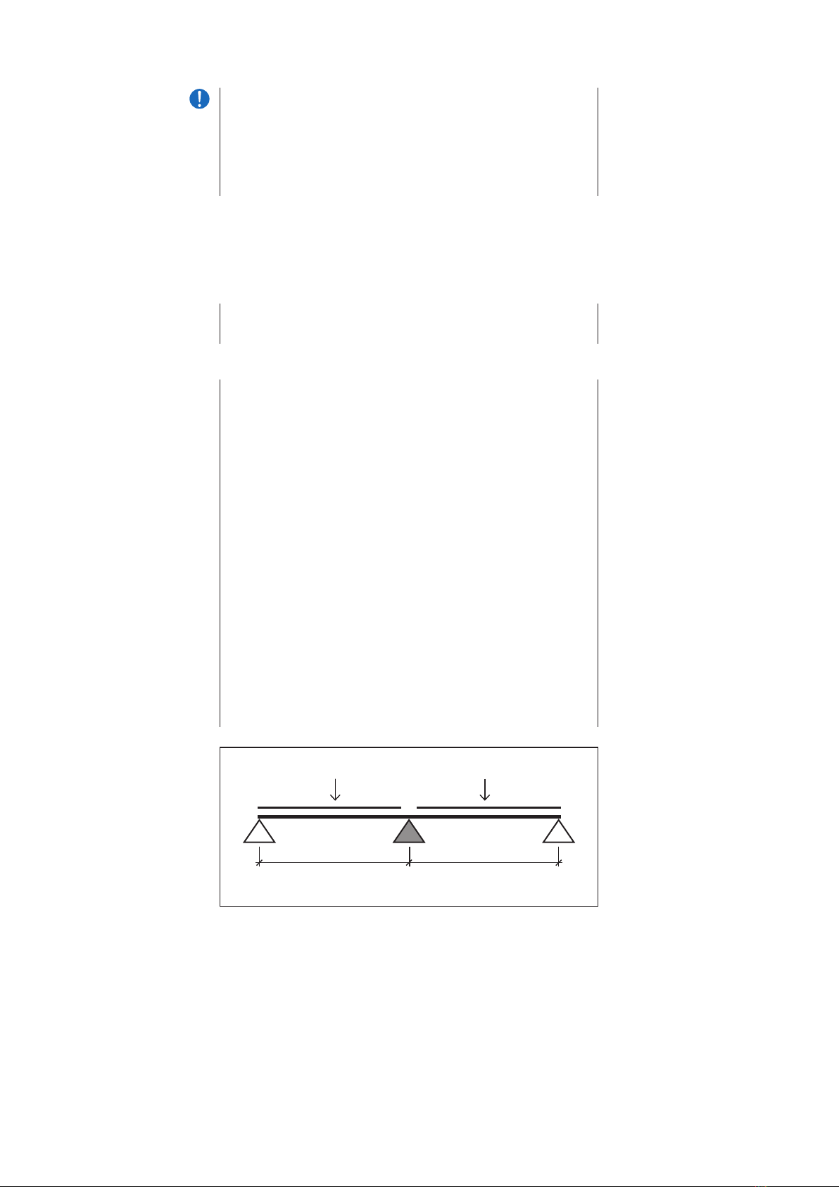
The track system should be designed with the load capacity of the hanging points:
The track system’s load (point load or uniform distributed load) is secured by the
hanging points.
The center hanging points’ weight load is higher than the weight load of the hanging
points at the end of the track (see also chapter 2.2.2).
The load capacity of the hanging points depend on the mounting nuts used. Replacing a
standard camlock nut with an adjustable nut or a HD nut can increase the load capacity.
If you still need a higher load capacity, or a replacement is not possible, you must
reduce the distance between the hanging points.
To dene the maximum hanging point distance for a given load weight, see the diagram
above.
IMPORTANT
Near a track splice the load bearing capacity of the track is lesser.
Compensate this fact by putting a suspension at a maximum distance of
100 mm from each track splice.
IMPORTANT
Make sure that under construction, suspension points and xing elements
being not part of the track system are dimensioned correctly.
1.7 Declaration of Conformity
1.8 System Options
According to the EU machinery directive (2006/42/EC) the Trumpf 95 track is considered
as a machine when it is used with a motorized operation system.
If Gerriets GmbH is assigned with setting up a complete Trumpf 95 system including
motor and control system we will conduct a conformity assessment. The CE mark will
be applied to the system.
If you merely procure the system components from Gerriets GmbH in order to set up the
system yourself, you are considered as the manufacturer according to the EU machinery
directive (2006/42/EC). In this case you are obliged to conduct the conformity testing
procedure yourself and Gerriets GmbH will only deliver a declaration of incorporation.
Manual or motor operation and control systems:
• ROPE-DRIVE: Manual operation with a continuous loop hemp rope Ø 22 mm.
• HAND-DRIVE: manual operation with hand crank.
• FRICTION-DRIVE: motor operation without rope. The motor moves via drive wheel
along the track.
• TRAC-DRIVE: Motor operation with continuous loop rope.
• G-FRAME 54 control unit.
• G-FRAME 54 frequency controller.
• Hand held remote control.
• Track switch, 2 positions, manual or motor operation, available with switch controller.
• Track switch, 3 positions, manual or motor operation, available with switch controller.

7
Operation Manual / TRUMPF 95
1.9 Safety Information The operating company (contractor) assumes the overall responsibility for the operation
of the technical system.
If the Trumpf 95 track system was installed by Gerriets GmbH you can assume that the
system does not represent a source of avoidable hazards once it has been handed over
to you.
However, this assume that installation and operating instructions of this manual are
observed!
We recommend that you conduct a risk assessment for the specic conditions under
which the system is to be operated on your premises and make arrangements in order
to rule out as far as possible any damage due to inappropriate operation and residual
hazards.
The details in the table under 4.1 may help you
Please observe in particular the following regulations:
• BGV A1: Principles of Prevention
• BGV A3: Electrical Installations and Equipment
• BGV C1 / GUV-V C1: Staging and Production Facilities for the Entertainment Industry
• BGG 912 / GUV-G 912: Principles for Testing Mechanical Facilities in Stages and
Studios - Machinery Directive 2006/42/EEC
• BGI 810-0: Safety for Productions and Events - Guideline
• BGI 810-2: Television, Radio and Film; Work Safety at Production Facilities
Suspensions:
• BGI 810-3: Safety for Productions and Events - Overhead Loads
• Machinery Directive 2006/42/EC
• TRBS 2131: Electrical Hazards
• TRBS 2111: Mechanical Hazards - General Requirements
• DIN 56950: Entertainment Technology - Machinery Installations - Safety Requirements
and Inspections
1Introduction

8
Operation Manual / TRUMPF 952System Installation
2.1 Qualication of the
set-up personnel
2.2 Preparation of the installation
2.2.1 Checking the completeness
and integrity of the delivery
2.2.2 System Design
NOTE
We recommend having the initial installation performed by expert personnel
of the company Gerriets GmbH.
If the installation is to be performed by your own personnel, make sure the
installation is done only by qualied personnel who carefully observe the
installation manual including its appendices.
The electrical installation may be performed only by qualied electricians.
Check immediately after receiving whether the delivery is complete and in accordance
with the delivery note by comparing also with the images in chapter “2.3 Track
Mounting” and check that no transport damage has occurred.
For designing your custom track system, please note the following points:
When you determine the track system length you must include the curtain stacking
space (length of each runner and master runner) and length of the needed compon-
ents such as end stops, return pulley, head pulley and motors at the ends of the track
system.
Stacking space calculation for each side of curtain:
Number of runners (approx. 4-5 runners per meter) x lengths of each runner
+ length of master runner
+ lengths of head and return pulleys
+ length of end stop (+ motor)
These questions help you to dene the correct number and type of hanging points:
• Track: what kind of load (point load or uniform distribute load) is appropriate?
• Which system position/application bears the highest load capacity (open curtain,
scenery attached to 1 or to 2 scenery carriers)?
• If considering a span width of less than 2 m: Which is the highest possible load
capacity weight for the most stressed hanging points?
Regard your system as a multi-span girder. The spans next to the center hanging point
are loaded with the maximum load capacity. Multiply the span load weight times 1.375.
The result is the approx. maximum load capacity of the center hanging point.
For further questions please contact our customer service team.
P = Point load q = Uniform distributed load I = Distance between spans
l l
q
or
P
q
or
P

9
Operation Manual / TRUMPF 952System Installation
2.2.2 System Design • Does the value exceed the maximum load capacity?
• Use the diagram in chapter 1.4 to verify the maximum span width.
The distance between the track end hanging points and the end of the track should be
as short as possible.
IMPORTANT
The maximum load capacity of the track system (see diagram in chapter
1.6) must not be exceeded. In addition, pay attention to the load capacity of
each single component. The load capacity of all parts is specied in chapter
2.3.1”System Parts Mounting”.
The track system’s load capacity is lower at the joint of two track sections.
Place the hanging points less than 100 mm away from the joints/splice
points.
Ensure that TRUMPF 95 is mounted to a stable structure.
Plan the track conguration including the maximum weight load and dene where
accessory parts, such as hanging points or rope guides, are mounted in the top groove
of the track.
Depending on the site of operation, different safety regulations may apply.

10
Operation Manual / TRUMPF 95
Track Mounting
Track Splice
Connects two track sections.
• Weight: 260 g.
Art-No 3115 0011
Track, Straight
With groove on top of track for accessories mounting.
Art.-No. Colour Length cm Weight g/rm
3115 1011 black 600 900
3115 1012 silver 600 900
3115 1021 black up to 600 900
3115 1022 silver up to 600 900
If you shorten a track section, the cut must be straight and
at a right angle. Deburr the cut edge to ensure a precise joint
connection of the track sections.
Track, Curved - with Splice
• Technical Technical details: see Track, Straight.
• 1/4 circle, 90° curve.
Art.-No. Colour Radius cm Weight g/piece
3115 1041 black 50 1.067
3115 1042 silver 50 1.067
3115 1061 black 100 1.774
3115 1062 silver 100 1.774
3115 1081 black custom curve -
3110 1082 silver custom curve -
2System Installation
2.3 Mounting of the track
2.3.1 TRUMPF 95:
System Parts Mounting
Track sections can be mounted directly to the ceiling structure or preassembled on the
oor.
The installation location should be secured as to prevent objects from
overhead from falling down.
If working at heights cannot be avoided, make sure that persons are secured
accordingly to situation and regulation.
IMPORTANT
Please consider the system parts mounting instructions in the following
chapter.
The following pages include drawings and descriptions of the TRUMPF 95 track system
as well as mounting instructions and useful tips.
Depending on which mounting nut you select, three load capacities are given.
These values always refer as following:
• Standard camlock nut (3115 0091) – lowest load capacity.
• Adjustable nut (3115 0071).
• HD adjustable nut (3115 0061) – highest load capacity.
In case the measurements in your copy can not be read clearly, please use the TECHNIC
manual or go to www.gerriets.com.

11
Operation Manual / TRUMPF 95
2.3.1 TRUMPF 95: System Parts Mounting
Joint Pin
• Ø 2,5 mm x 20 mm.
For precise track section connection (included in standard
delivery).
Track sections are centered by 2 joint pins and friction-locked
connected with a track splice.
Before connecting the track sections, slide required camlock
nuts (3115 0071/3115/0061) into top groove of track.
Art-No 3110 9115
Camlock Nut
For accessories mounting. Premounted to all accessories
(M8 x 20 mm screw).
• Weight: 10 g.
• Load capacity in the groove: 45 kg.
• Place the camlock nut where needed in the track groove.
• Loosen screw until almost removed.
• Tighten screw until noticeable resistance. Keep on tightening.
The camlock nut should turn 90° and securely t into the top
groove of the track.
• Double-check if camlock nut is turned 90° in the groove of
track.
• If the camlock nut is not in the required position (compare
image) repeat the steps above.
Art-No 3115 0091
2System Installation
Connection Pin, stainless steel
• Steel pin Ø 2,5 mm.
• For easier disassembling of the tracks.
• Tapered cone.
Art.- No. 3100 9116 The stainless steel connection pin can be used where tracks
need to be demounted and remounted often. Connecting track
parts is easier than when using a standard joint pin.
Adjustable nut
• Positioned in top groove of the track.
• With hole to accept M8 bolt.
• Load capacity in groove: 60 kg.
Art-No 3115 0071

12
Operation Manual / TRUMPF 95
2.3.1 TRUMPF 95: System Parts Mounting
2System Installation
HD adjustable nut
• For heavy-duty applications. Only for straight applications.
With hole to accept M8 bolt for track mounting.
• Weight: 72 kg.
• Load capacity in groove: 80 kg.
Slide HD adjustable nut in groove of track and secure it at the
desired position by tightening the screws.
Art-No 3115 0061
End Stop
With hole to attach the curtain camlock nut mounted.
• Weight: 130 g.
Art-No 3115 0011
G-TWIST Ceiling Mount Bracket
• For ceiling/surface mounting of TRUMPF 95 track.
• With two slots for 6 mm screws.
Art.-No. Colour Weight g/piece
3115 8161 black 41
3115 8162 silver 41

13
Operation Manual / TRUMPF 95
2.3.1 TRUMPF 95: System Parts Mounting
2System Installation
1
234
Ceiling Installation Ceiling Installation
Expansion anchor + screw Wood screws
5 x 40
Installation using G-TWIST ceiling bracket (do not place
more than 4“ / 10 cm from track splice)

14
Operation Manual / TRUMPF 95
2.3.1 TRUMPF 95: Walk-Along Track / Overview
Track system without motor operation. Manual opening and
closing of the curtain.
The basic track system to move a curtain/scenery along a
track.
Please note height measurements of all components for
system design and installation.
Please calculate length of each runner and master runner for
stacking space.
Walk-Along Track
Mounting Considerations
2System Installation
3100 0025
2-Rad-Laufwagen, schwarz
/ Chariot simple, noir /
2-Wheel Runner, black
3115 0021
Feststeller / Arrêt / End Stop
3115 101-
Schiene gerade, schwarz
oder natur eloxiert / Rail
droit, noir ou alu anodisé
/ Track, straight, black or
clear anodized
3115 0091
Nutenstein (nicht sichtbar) /
Ecrou autoblocant
(non visible) / Camlock Nut
(not shown)
3115 0011
Schienenverbinder (nicht
sichtbar) / Raccord de rail
(non visible) / Track Splice
(not shown)
3115 8011
Rohrhaken, direkt
/ Crochet de xation -
direct / Hook Clamp

15
Operation Manual / TRUMPF 952System Installation
34
43
90
140
109
50
472540
Seitenansicht / Vue de face / Side View Vorderansicht / Vue en coupe / End View
3100 0031
4-Rad-Laufwagen / Chariot
double / 4-Wheel Runner
3100 0061
Laufwagen HD mit Über-
zugbügel / Conducteur HD
avec patte de croisement
/ HD Runner with overlap
arm

16
Operation Manual / TRUMPF 95
Ceiling Mounting Plate
For track systems without cord operation.
For direct ceiling mounting of tracks. With hole to accept M6
bolt (screw and anchor not included).
Distance: every 1-2 m, depending on weight load.
• Weight: 185 g.
• Load capacity: 38 kg.
• For dening the distance between mounting plates,
use load capacity table in chapter 1.6!
• Verify that the ceiling structure and all attachment
accessories such as bolts or anchors are stable
(we recommend using M6 screws in combination
with metal anchors).
• Screw ceiling mounting plate to ceiling.
• Squeeze both plates to the track and tighten
the M4 nuts!
4-Wheel Runner
Curtain attachment via tie line, carabiners up to 60/6, shackles
or curtain hooks.
• Load capacity: 20 kg.
• Weight: 110 g.
4+4 Master Runner
• Load capacity: 20 kg.
• Weight: 180 g.
Center Overlap Bracket
For parallel track sections overlap at center (2 to 3 brackets per
overlap). With 12.5 hole to accept hook clamp 3115 8011.
Mounted via 2 camlock nuts (included in delivery).
• Weight: 210 g.
• Load capacity: 80 kg.
Art-No 3100 8021 / 3100 8022
Art-No 3100 0031
Art-No 3100 0011
Art-No 3115 0031
2.3.1 TRUMPF 95: Walk-Along Track / System Parts Mounting
2System Installation
G3-Silence 2-Wheel runner
• With integrated slot allowing curtain to be hung high on carrier
so that most of the carrier is hidden behind the curtain‘s top
edge.
• With 360º swivel attachment.
• Same height dimension as previous model (Ref. 3100 0021/22).
• Load capacity: 10 kg*.
• Weight: 40 g.
Art-No 3100 0025 black / 3100 0026 white
* Before loading the runners,
verify that the weight does not
exceed the load capacity of the
track system hanging points.

17
Operation Manual / TRUMPF 95
Hook Clamp, Direct
With attachment kit for direct track mounting (camlock nut and
M8 bolt).
• For pipe battens installation, pipe Ø 48 mm to Ø 60 mm.
• Load capacity: 50 kg.
• Weight: 605 g.
Hook Clamp, Suspension
With attachment kit for mounting directly to suspension
brackets or center overlap brackets.
• For pipe diameter 48-60 mm.
• Load capacity: 50 kg.
For mounting a double track system with center overlap via
hook clamps, off-set mounting plate 3115 8021 is necessary
to align the hook clamps.
Off-Set Mounting Plate
For suspension of a double track with hook clamps (not in
overlap area).
• Load capacity: 45 kg.
Wall Mount Bracket 150*
With attachment kit for direct track or suspension mounting.
• Wall distance adjustable.
• Length: 150 mm.
• Weight: 465 mm.
• Load capacity: 45 kg.
For use on a walk-along system. If used on a side cord or top
cord system, different attachment kits must be used.
Please note when ordering.
Art-No 3100 8011
Art-No 3110 8011
Art-No 3115 8021
Art-No 3100 8061 / 3100 8062
Wall Mount Bracket 250*
See 3100 8061, with arm length 250 mm.
• Weight 624 g.
• Load capacity: 45 kg.
Art-No 3115 8071 / 3115 8072
2.3.1 TRUMPF 95: Walk-Along Track / System Parts Mounting
* Mount the wall mount bracket
securely to the wall with 2
bolts. Make sure there is
sufcient structure on or behind
wall when bolting.
The wall mount bracket must
be securely fastened to the wall
before the track is connected.
2System Installation

18
Operation Manual / TRUMPF 95
HD Runner
4 top load bearing and 4 side stabilizing wheels.
With fall protection (in case of load bearing wheels failure).
• Load capacity bis 35 kg.**
• Weight: 720 g.
HD Scenery Carrier
Technical details: see 3100 0051, but with swivel attachment.
• Weight: 640 g.
• Swivel with M8 bolt for scenery atttachment.
HD Scenery Carrier with Scenery Attachment
Technical details see 3100 0071.
Attachment plates. With 2 holes to accept countersunk bolt,
1 hole to accept 8 mm bolt. For scenery thickness 8-60 mm.
• Weight: 1.009 g.
Scenery Attachment
• If necessary, separate clamping plates from scenery carrier by
removing M5 bolt.
• Attach scenery or scenery frame to clamping plates. Use an
end-to-end M8 bolt for attaching the scenery and wood
screws for positioning the scenery between the clamping
plates.
• According to the risk assement a secondary safety component
should be used!
Art-No 3100 0051
Art-No 3100 0071
Art-No 3100 0101
** Depending on the distance
between suspension points
and the mounting nut type, the
weight load must be below the
given runner/carrier load
capacity.
Please see diagram in chapter
1.6.
2.3.1 TRUMPF 95: Walk-Along Track / HD Carrier Options
HD Runner with Overlap Arm
HD runner for up to 35 kg weight load.
For single track systems with center overlap.
• Weight: 815 g.
Art-No 3100 0061
top view
x1 = 17,5 cm, x2 = 35 cm
x2
x1
x1
Wall Mount Bracket 380 *
See 3100 8061, but arm length 380 mm.
• Weight: 1.106 g.
• Load capacity: 30 kg.
Art-No 3115 8061 / 3115 8062
* Mount the wall mount bracket
securely to the wall with 2
bolts. Make sure there is
sufcient structure on or behind
wall when bolting.
The wall mount bracket must
be securely fastened to the wall
before the track is connected.
2System Installation

19
Operation Manual / TRUMPF 95
2.3.1 TRUMPF 95: Cord Operation / Accessories
Return Pulley
Returns rope at the end of the track.
Mounted via two camlock nuts (standard delivery)
• For use with rope up to Ø 8 mm.
• Weight: 825 g.
Head Pulley
Diverts operation cord to oor pulley.
Mounted via 1 camlock nut (standard delivery).
• For use with rope up to max. Ø 8 mm.
Always install 2 suspension points in head pulley area to
reduce stress.
Polyester Rope Ø 8 mm
• Standard rope.
• Works for manual operation.
• Color: black (also available in white).
• Tensile strength: approx. 1163 daN.
• Non-stretch.
Return and Tensioning Pulley
Return pulley with automatic tensioning of operating rope.
Mounted via 3 camlock nuts (included in standard delivery).
• For use with rope up to Ø 8 mm.
• Tensioning distance: 140 mm.
• Weight: 1250 g.
Art-No 3115 0051
Art-No 3115 0041
Art-No 4104 1182
Art-No 3197 0001
2System Installation

20
Operation Manual / TRUMPF 95
2.3.1 TRUMPF 95: Side Cord Operation / Overview
Side cord operation is suitable for low clearance applications.
Side cord operation systems are lower and narrower than top
cord systems.
Side cord operation is a basic cord guide system that is
economical and easy to install.
Side cord operation is only for straight, single track
applications up to 12 m long.
A curtain center overlap up to 35 cm is possible by using
overlap arms.
Side Cord Operation
Important
2System Installation
3115 0051
Umlenkrolle / Poulie de
renvoi / Return Pulley
3115 4012
Zugwagen mit Überzugbü-
gel / Chariot conducteur +
patte de croisement / HD
Master Runner
3115 0091
Nutenstein (nicht sichtbar) /
Ecrou autoblocant
(non visible) / Camlock Nut
(not shown)
3115 0011
Schienenverbinder (nicht
sichtbar) / Raccord de rail
(non visible) / Track Splice
(not shown)
3100 0031
4-Rad-Laufwagen / Chariot
double / 4-Wheel Runner
3100 0025
2-Rad-Laufwagen, schwarz
/ Chariot simple, noir /
2-Wheel Runner, black
3115 0021
Feststeller / Arrêt / End Stop
3115 101-
Schiene gerade, schwarz
oder natur eloxiert / Rail
droit, noir ou alu anodisé
/ Track, straight, black or
clear anodized
3115 4021
Seilführung / Guidage de
drisse / Side Cord Guide
Table of contents
Popular Dj Equipment manuals by other brands

Beamz Pro
Beamz Pro StarColor 540Z user manual

Lightmaxx
Lightmaxx LED Mega PAR 64 144 Watt RGBW user manual

American DJ
American DJ Rover User instructions

Chauvet Professional
Chauvet Professional OVATION P-56VW Quick reference guide

Behringer
Behringer EUROLIGHT LC2412 user manual

DJ-Tech
DJ-Tech DIF-2S user manual