Gesan DVAS 450 E User manual


STANDBY GENERATOR SETS V-6.4
1
1. WELCOME............................................................................................................................................3
2. BASIC SAFETY RULES ......................................................................................................4
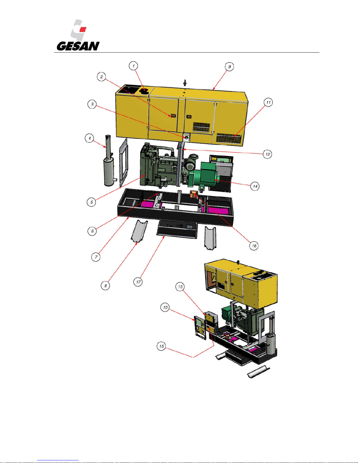
3. DESCRIPTION OF GENERATOR SET...............................................................................................6
3.1. SOUND INSULATION.............................................................................................................. 11
3.2. CONTROL PANEL .................................................................................................................... 12
3.3. ELECTRICAL CONFIGURATION........................................................................................... 15
3.4. RETENTION BATH...................................................................................................................16
4. INSTALLATION OF THE GENERATOR SET................................................................................. 17
4.1. UNLOADING AND TRANSPORT........................................................................................... 17
4.2. INTALLATION PRINCIPLES................................................................................................... 18
4.2.1. Premises........................................................................................................................... 18
4.2.2. Ventilation and cooling.................................................................................................... 19
4.2.3. Fuel..................................................................................................................................19
4.2.4. Automatic fuel transfer system........................................................................................19
4.2.5. Exhaust ............................................................................................................................20
4.2.6. Generator set startup........................................................................................................21
4.2.7. Electrical connection ..........................................................................................22
4.2.7.1. Safety instructions...............................................................................................22
4.2.7.2. Installation of CONTROL section : ......................................................... 27
4.2.7.3. Installation of ELECTRICAL POWER section: .................................................. 28
4.2.7.4. Earthing:............................................................................................................. 30
4.2.7.5. Motorized changeover switches:......................................................................... 30
4.3. STORAGE ..................................................................................................................................30
5. STARTUP ............................................................................................................................................ 31
5.1. POWER FACTOR AND GENERATOR SETS ......................................................................... 32
5.2. LIGH LOAD OPERATION ON DIESEL ENGINES ................................................................32

STANDBY GENERATOR SETS V-6.4
2
6. OPERATION MANUAL..................................................................................................................... 33
6.1. CONTROL PANEL COMPONENTS ........................................................................................33
6.1.1. Deep sea 4420 digital control module.............................................................................. 35
6.1.2. DEEP SEA 7310/7320 Digital Control Module .............................................................. 39
6.1.3. INTELIGENNT Digital Control Module ..........................................................................50
7. MAINTENANCE OF GENERATOR SET..........................................................................................56
7.1. PRIOR TO MAINTENANCE..................................................................................................... 56
7.2. DURING MAINTENANCE .......................................................................................................56
7.3. MAINTENANCE CHART .........................................................................................................60
8. TROUBLESHOOTING .......................................................................................................................61
9. PROTECTION FROM THE ENVIRONMENT ..................................................................................62
10.WARRANTY....................................................................................................................................... 62
11.NOISE LEVEL.....................................................................................................................................63
12.DECLARATION OF CONFORMITY .....................................................................................63
13.APPENDIX 1: FIGURES.....................................................................................................................64
14.APPENDIX 2: IMAGE INDEX........................................................................................................... 66
15.APPENDIX 3: PRE-DELIVERY INSPECTION DOCUMENT.........................................................67
16.APPENDIX 4: DERATING OF ENGINE POWER RATING:...........................................................68

STANDBY GENERATOR SETS V-6.4
3
1. WELCOME
Thank you for choosing a GRUPOS
ELECTRÓGENOS EUROPA S.A.generator set.
The purpose of this manual is to familiarize the
user on how to use and work with the electrical
generator, its components and maintenance.
We recommend a carefully reading this
document prior to working with the equipment to
ensure its correct use.
Save this manual for future reference and if the
generator set is resold be sure to include the
manual along with the unit.
The following is a general description of the unit
and the information necessary for installation,
operation and preventive maintenance.
Additionally, you should have received a
specific user manual for the Engine and
Alternator, electrical setup, a set of keys, ATS
(upon order), silencer or exhaust tube and
flexible tube (supplied separately for open-skid
units).
Should you have any problem with the
equipment provided, please contact the
distributor directly.
GRUPOS ELECTRÓGENOS EUROPA S.A.,
in a constant effort towards product
improvement, shall revise its manuals and
include improvements made to the supplied
units. Thus the information contained in this
document is subject to change without prior
notice and without obligation to update.

STANDBY GENERATOR SETS V-6.4
4
2. BASIC SAFETY RULES
Safety precautions and recommendations for handling the Electrical Generator supplied by GRUPOS
ELECTRÓGENOS EUROPA S.A.
1) Do not allow the unit to be used by non-authorized personnel or minors not accompanied by an adult.
2) Use the necessary individual protection equipment.
3) Ground the machine and ATS panel.
4) Make sure there is sufficient lighting on the genset and on the control panels before start-up; the
minimum lightning level should be 20 lux.
5) Do not install the open-skid electrical generator outdoors: risk of electrocution and non-functioning.
6) The connection should be made by a qualified electrician in accordance with current norms and
regulations. An incorrectly made connection can cause electrical feedback with electrocution hazards
for anyone working with the mains power supply. The mains connection should always be made using
an automatic transfer switch (ATS); if none has been supplied, contact your distributor or GRUPOS
ELECTRÓGENOS EUROPA S.A.
7) The supply line between the generator set and the consumers should be protected by means of a
differential relay for protection against earth leakage.
8) The electrical installation between the generator unit and ATS should be protected using
electromagnetic circuit breaker for protection against short circuits and overcurrents. The circuit breaker
is supplied optionally by GRUPOS ELECTRÓGENOS EUROPA S.A.
9) Do not operate the unit with the doors open: risk of electrocution, burns or entrapment. Be sure the
doors are closed with keys before the start-up.
10) The exhaust system generates enough heat to ignite some materials. Therefore, never install the
generator set near flammable materials or near materials that may ignite easily or in locations where the
risk of a fire occurring is high.
11) The gases generated by the set’s engine are highly toxic and may result in death. Never inhale the
exhaust gases generated by the set. If the unit must be operated in an enclosed area or in a poorly
ventilated area, the engine exhaust gases must be routed towards the exterior for a safe operation.
12) Do not touch the engine or the exhaust during operation of the generator set: Severe burns may occur.
The exhaust hot areas are protected against accidental contact. In areas where this type of protection is
not feasible, the risk is indicated using appropriate signs.
13) Ensure proper ventilation in the area where the generator is installed in order to guarantee sufficient
flow of cooling air.

STANDBY GENERATOR SETS V-6.4
5
14) Know how to stop the unit in case of emergency. Be special careful with his handling and storage.
15) For refueling the engine, the generator set incorporates an exterior fuel filler neck and cap for filling the
tank with diesel. Never refuel with the engine running or in poorly ventilated areas; remember that fuel
vapors are toxic and flammable. Take the necessary safety precautions when handling fuel; the use of
gloves and safety goggles is recommended.
16) The fuel used is flammable, volatile and toxic. Prevent any spill and carefully wash your hands after
handling.
17) If you notice abnormal behavior by the generator set, stop the unit, and then locate, examine and resolve
the potential failure of the unit prior to restarting. Contact our technical services department if needed.
18) Keep the unit at least one meter away from buildings or other units.
19) Be cautious when switching or installing batteries as they contain acids which are highly hazardous.
Avoid spills and use protection to avoid contact with the skin and eyes. In case of accidental contact,
rinse thoroughly with water and contact a doctor service immediately.
20) In case of ingestion of battery acid, drink large amounts of water and milk and contact a doctor
immediately.
21) Use only distilled water in the battery, the tap water
22) If a battery is filled above the maximum level, the electrolytes will spill out; if this happens, clean the
area quickly to avoid corrosion of the parts it has come in contact with.
23) Frequently clean the unit to avoid obstructions or the entry of foreign elements into the unit (dust,
moisture, etc.).
24) Regularly inspect the unit’s electrical cables.
25) Engine oil is toxic and hazardous to the environment. Adopt the necessary safety measures when
handling engine oil. Prolonged exposure to used engine oil may cause skin cancer. Carefully wash your
hands after handling.
26) Avoid oil spills on both the inside and outside of the generator. In case of oil spill on the inside of the
unit, clean it properly as it could potentially become a flammable material.
27) Do not overfill the tank and make sure it is closed properly after filling. Use extreme precaution if fuel
is spilled: the vapors and the fuel itself are flammable. Clean the area completely before starting up the
unit.
28) Do not smoke or bring any flames or sparks in the vicinity of the electrical generator: risk of explosions.

STANDBY GENERATOR SETS V-6.4
6
3. DESCRIPTION OF GENERATOR SET
Following you have general overview of the generator set (doesn´t match with the delivered genset) and
its different configurations manufactured by GRUPOS ELECTRÓGENOS EUROPA S.A.
Image 1- Generator set with sound proof canopy.
Image 2- Generator set without canopy

STANDBY GENERATOR SETS V-6.4
7
Image 3- Detailed view of Insonorized genset

STANDBY GENERATOR SETS V-6.4
8
1) Coolant tank hatch
2) Side access door
3) Fuel tank cap
4) Exhaust silencer
5) Engine
6) Shock absorbers
7) Base frame
8) Base support
9) Canopy
10) Electrical Panel Doors
11) Ventilation grill
12) Lifting frame and eyebolt
13) Control panel
14) Alternator
15) Electrical power panel
16) Battery
17) Fuel tank

STANDBY GENERATOR SETS V-6.4
9
Image 4- Detailed view of openskid genset

STANDBY GENERATOR SETS V-6.4
10
1) Lifting frame
2) Engine
3) Shock absorbers
4) Base frame
5)
Fuel tank
6) Base support
7) Control panel
8) Electrical power panel (optional)
9) Alternator
10) Battery

STANDBY GENERATOR SETS V-6.4
11
3.1. SOUND INSULATION
The supplied unit may be:
Soundproofed. Includes sound-insulating canopy.
Over base support Open skid. You must keep in mind that in compliance with current
regulations may require that proper room sound insulation will be provided for this model. (See
4.2 INSTALLATION)
Each Electrical Generator is provided with a sticker indicating the level of noise output produced and the
need to use hearing protection.
Noise output 90 dBA Noise output 114 dBA Use of hearing
protection required.
Image 5- Noise output pictograms and hearing protection required
The noise level has been measured according to the European directive 2000/14/EC and in compliance
with the maximum levels established by directive 2005/88/EC.
Please consider the local and national regulations that could be more restrictive. In any case, it’s the
installer and owner responsibility to comply with the current legislation

STANDBY GENERATOR SETS V-6.4
12
3.2. CONTROL PANEL
The unit provided may be controlled by different modules depending on the type of function it has been
designed to perform.
Image 6- Generic Control Panel
1-3 →.Electrical Gauges
4→ Hour meter
5→ Earth leakage relay (It may be
installed inside the electrical panel)
6→ Indication lamps (green, red, yellow)
7→Mode Switch
8→ Engine Gauges
AMMETER (OPTIONAL IN DEEP SEA 4420 CONTROL PANNEL)
LOCK
LOCK
DIFFERENTIAL
(OPTIONAL)
AUTOMATIC
CONTROL UNIT
EMERGENCY
BUTTON

STANDBY GENERATOR SETS V-6.4
13
3.2.1. INTELIGENNT DIGITAL CONTROL PANNEL
I you have adquire a genset with INTELIGEN control panel; the electrical box will have an appearance as
shown in the figure below:
Image 7-Control panel with InteliGen N T module
LOCK
DIFRERENTIAL
(OPCIONAL)
LOCK
EMERGENCY
BUTTON

STANDBY GENERATOR SETS V-6.4
14
3.2.2. PLACA DIGITAL DE CONTROL DEEP SEA
I you have acquire a genset with INTELIGEN control panel; the electrical box will have an
appearance as shown in the figure below:
Image 8-Control panel with DEEP SEA Control module
DIFERENCIAL
(OPCIONAL)
CERRADURA
CERRADURA
AM
METER

STANDBY GENERATOR SETS V-6.4
15
3.3. ELECTRICAL CONFIGURATION
The supplied unit may be one of three types:
The generator unit is supplied with automatic transfer switch (ATS).
The generator unit is supplied without ATS. Note that its installation is required.
Image 9- Load Transfer diagram
Note: PCCB = Power Control Circuit Breaker
ATS may be with contactors, motorized changeover switch or motorized circuit breakers
The genset is supplied as “Standby by signal” without ATS. The Electrical Generator
stands idle until it receives a signal from an autonomous external system which monitors the mains
and controls the automatic transfer switch for startup.

STANDBY GENERATOR SETS V-6.4
16
3.4. RETENTION BATH
The generator set may include a built-in retention bath to prevent spills from the unit—such as fuel, oil or
coolant—with a capacity of 110% with respect to the total volume of liquids.
It is the responsibility of the installer and the owner to take the appropriate measures to avoid
contaminants spillage, in case your genset doesn´t includes retention bund and consider that it should have
it, please contact with our technical service.
Image 10- Retention Bath
1) 4 drain plugs, 2 on each side of the pan
2) Slots for inserting forklift arms
3) Retention bath level senders (optional)
2
2
1
1
3

STANDBY GENERATOR SETS V-6.4
17
4. INSTALLATION OF THE GENERATOR SET
In this part of the manual it is described how to install a “generic” generator set composed of a diesel
engine, alternator and electrical panel supplied by GRUPOS ELECTROGENOS EUROPA S.A. For other
applications, our technical service will advise.
4.1. UNLOADING AND TRANSPORT
Uploading and transport must be performed by qualified personal, taking into account minimal security
conditions.
The floor must be capable of supporting the full weight of the Generator and the forklift.
Make sure that the battery is disconnected.
Make sure that the fuel tank is empty.
Place the arms of the forklift below the chassis at an equal distance with respect to the
lifting frame.
With a hoist, raise the unit using the lifting frame eyebolt.
The image below shows a drawing of a generator unit which includes a frame with a single lifting point.
Image 11- Lifting frame

STANDBY GENERATOR SETS V-6.4
18
4.2. INTALLATION PRINCIPLES
4.2.1. Premises
The following considerations must be kept in mind: the fuel supply, ventilation of the premises, the
output and direction of the exhaust gases and the noise produced.
Dimensions
The dimensions should allow for the various required maintenance or disassembly operations. A
minimum of one meter should be left on all sides of the generator to allow for the doors to be opened.
Openings
The premises should have an entrance that is large enough for the generator to pass through and openings
large enough for ventilation (fresh-air intake and radiator hot air outlet), with the appropriate surface area
based on the generator’s output, the premises’ cooling system and the soundproofing system used.
GRUPOS ELECTRÓGENOS EUROPA S.A. does not recommend installing canopied units in closed
spaces.
If the unit must be installed in an enclosed space, it is recommended to use an open-skid model and
soundproof the work area, in keeping with the current fire-prevention regulations.
The following image shows a typical installation of an open-skid unit in a closed space.
Image 12- Detailed view of installation of an open-skid unit

STANDBY GENERATOR SETS V-6.4
19
1) Air intake grill. Will be at least 1.4 times the surface area of the engine’s radiator panel.
2) Smoke exhaust line. This will be explained in more detail later.
3) Silencer. Must be firmly installed and fastened to a stable structure.
4) Smoke exhaust outlet. Smoke must flow out through a point which impedes its re-entry into the
space where the working unit is installed.
5) Radiator air outlet grill. Will be at least 1.25 times the surface area of the engine’s radiator panel.
6) Cooling air channel. Prevents re-entry of hot air into the space where the unit is installed.
7) Optional external fuel tank (optional).
4.2.2. Ventilation and cooling
The heat produced by the generator’s thermal engine must be evacuated from the premises.
The heat is generated by the cooling of the cylinders, the radiation from the engine block, the exhaust pipe, the
cooling of the alternator and the radiator air output.
Insufficient ventilation could produce an increase in the ambient temperature of the premises and cause the
generator to lose engine power until finish in a shut down.
4.2.3. Fuel
In keeping with current regulations, special attention should be paid to the storage of fuel, which is classified
as a hazardous product. The installation of the generator will include a day tank and an optional external fuel
storage tank.
Depending on the output of the generator, the fuel tank may be external instead of being built into the base
frame. This tank should be installed within a maximum distance according to the engine fuel pump suction
capability (see the Engine manufacturer’s manual). The installation will be carried out according to current
regulations.
4.2.4. Automatic fuel transfer system
The unit may include a self-suction, eccentric fuel transfer pump (SAB-BE) for the transfer of the fuel from an
external fuel tank to the internal one. This pump will self-prime with self-adjusting blades. Includes a recirculation
bypass valve. The pump has an internal removable filter, which must be used.
Image 13- SAB-BE Pump
Table of contents
Other Gesan Portable Generator manuals
Popular Portable Generator manuals by other brands

Generac Power Systems
Generac Power Systems NP Series installation manual

Moritex Schott
Moritex Schott MLEK-D770W4LRD instruction manual

DEI
DEI PVX-4000-2kV Operation manual

Honeywell
Honeywell 0061520 owner's manual

Agilent Technologies
Agilent Technologies ESG-D Series Installation notes

Hyundai
Hyundai DHY2500L/E user manual