Gesan Rental Series User manual


RENTAL & SILENT ENERGY RENTAL GENSETS 4.4
1
Contenido
1 WELCOME............................................................................................................................................3
2 BASIC SAFETY RULES.......................................................................................................................4
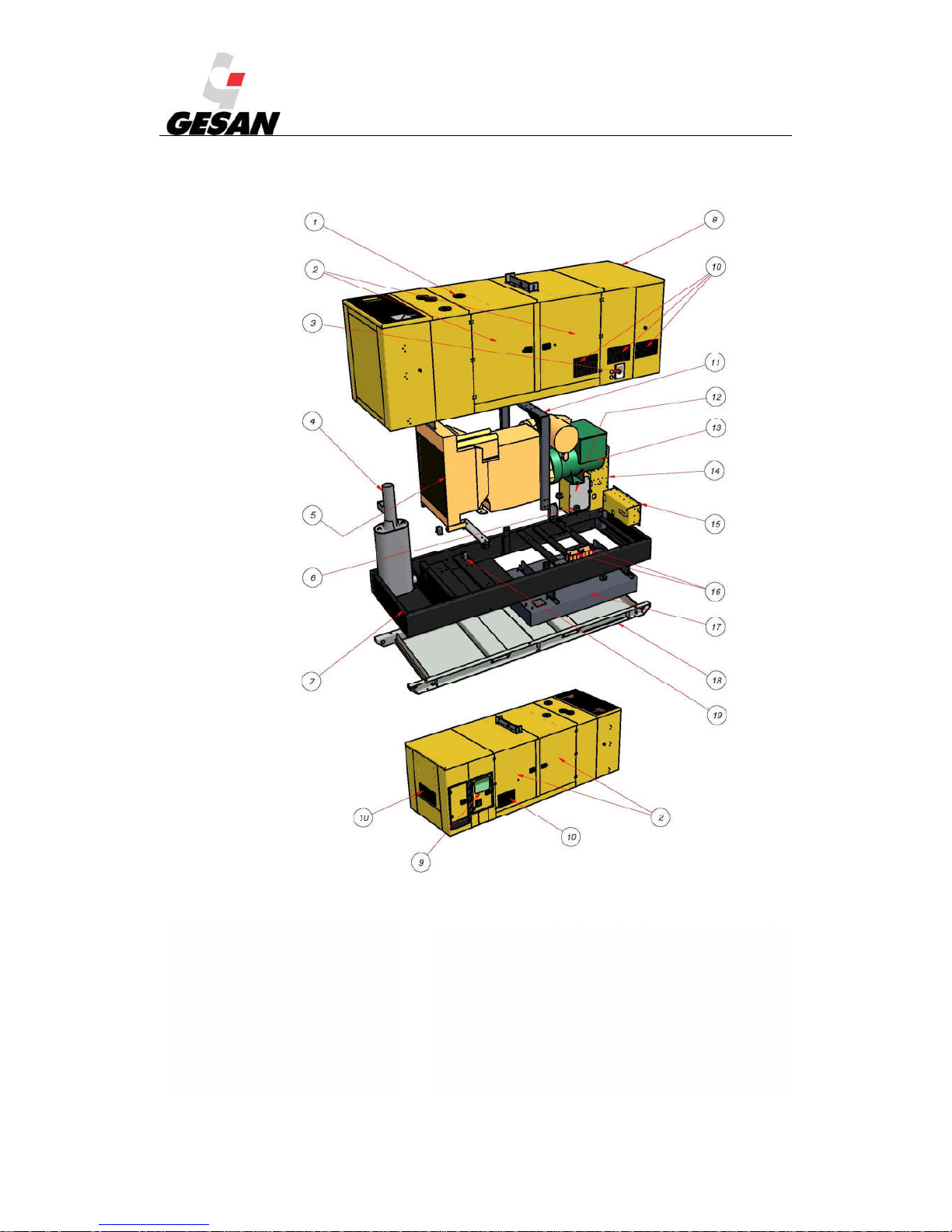
3 DESCRIPTION OF THE GENERATOR SET ......................................................................................6
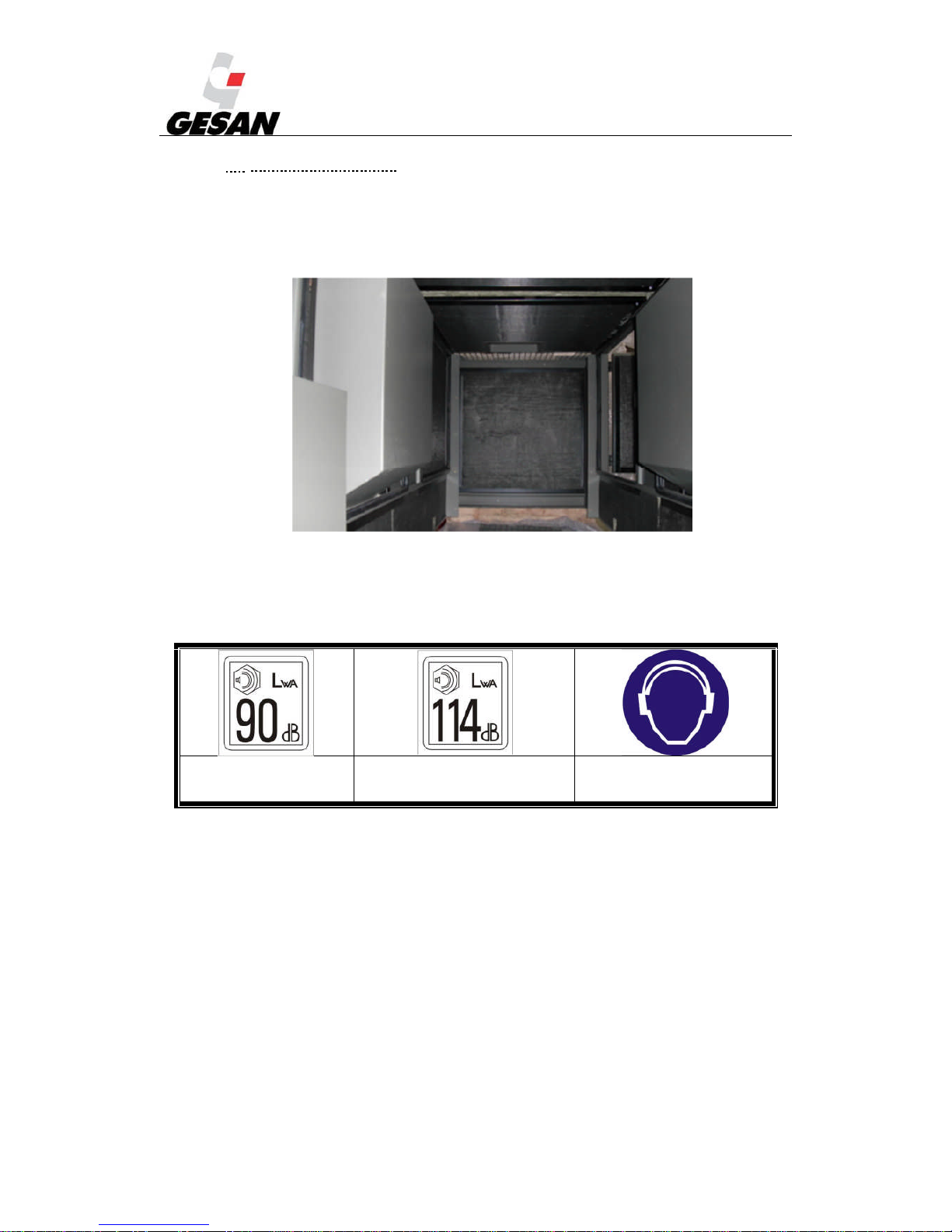
3.1. SOUND INSULATION ...................................................................................................................8
3.2. CONTROL UNITS...........................................................................................................................9
3.1.1. DEEP SEA digital control plate.......................................................................................10
3.1.2. INTELIGEN digital control plate....................................................................................11
3.2. TRAILER .......................................................................................................................................12
3.3. LIQUID COLLECTION TRAY.....................................................................................................14
4. INSTALLATION OF THE GENERATOR SET .................................................................................15
4.1. UNLOADING AND TRANSPORT...............................................................................................15
4.2. INSTALLATION OF MOBILE UNITS ........................................................................................17
4.2.1. Location...........................................................................................................................17
4.2.2. Fuel..................................................................................................................................17
4.2.3. Exhaust ............................................................................................................................19
4.2.4. Starting the generator set .................................................................................................19
4.2.5. Electrical connection........................................................................................................21
4.3. STORAGE......................................................................................................................................23
5. COMMISSIONING AND STOPPING................................................................................................24
5.1. GENERATOR SETS AND POWER FACTOR CORRECTORS..................................................24
5.2. OPERATION AT LOW LOAD IN DIESEL ENGINES................................................................25
6. OPERATION MANUAL.....................................................................................................................26
6.1. SWITCHBOARD COMPONENTS...............................................................................................26
6.2. DEEP SEA 7310 CONTROL MODULE.......................................................................................29
6.3. INTELIGENNT DIGITAL CONTROL MODULE (OPTIONAL)..................................................40
7. MAINTENANCE OF THE GENERATOR SET.................................................................................46
7.1. BEFORE MAINTENANCE...........................................................................................................46
7.2. DURING MAINTENANCE...........................................................................................................46
7.3. MAINTENANCE TABLE .............................................................................................................49
8. SOLUTION OF BREAKDOWNS .......................................................................................................51

RENTAL & SILENT ENERGY RENTAL GENSETS 4.4
2
9. PROTECTION OF THE ENVIRONMENT.........................................................................................51
10.WARRANTY.......................................................................................................................................52
11.NOISE LEVEL.....................................................................................................................................53
12.DECLARATION OF CONFORMITY ....................................................................................53
13.ANNEX 1: PICTOGRAMS..................................................................................................................54
14.ANNEX 2: SILENT-ENERGY RENTAL: ..........................................................................................56
14.1. DESCRIPTION OF THE GENERATOR SET....................................................................56
14.2. VARIATIONS IN THE ELECTRICAL CONFIGURATION:...........................................57
14.3. VARIATIONS IN THE CONTROL INSTALLATION: .......................................58
14.3.1.Switchboard supplied by GRUPOS ELECTRÓGENOS EUROPA S.A.........................58
14.3.2.Switchboard not supplied by GRUPOS ELECTRÓGENOS EUROPA S.A...................59
14.3.3.“Emergency by signal” generator set:..............................................................................60
14.3.4.POWER installation: ..........................................................................................60
14.4. ATYS SWITCHES:.............................................................................................................60
14.5. ADDITIONAL COMPONENTS SUPPLIED WITH THE SILENT ENERGY RENTAL
UNITS: 61
14.5.1.DEEP SEA 7320 Digital Control MODULE...................................................................61
14.5.2.Lightning..........................................................................................................................72
14.5.3.Silent blocks in doors.......................................................................................................72
14.5.4.AVR in switchboard ........................................................................................................73
15.ANNEX 3: PICTURES INDEX:..........................................................................................................75
16.ANNEX 4: DERATING OF ENGINE POWER RATING:.................................................................76
16.1. DERATING OF POWER RATING OF TTURBOCHARGED ENGINES WITHOUT
CHARGE AIR COOLING:....................................................................................................................76
16.2. DERATING OF ENGINE POWER RATING OF TURBOCHARGED ENGINES WITH
CHARGE AIR COOLING:....................................................................................................................77
16.3. DERATING OF ENGINE POWER RATING OF NATURALY ASPIRED ENGINES:...78
1

RENTAL & SILENT ENERGY RENTAL GENSETS 4.4
3
WELCOME
Thank you for acquiring a GESAN generator set.
The purpose of this manual is to describe the use and operation of the generator set, its components
and maintenance.
It is recommended that this manual be read carefully prior to working with the equipment for a
proper use.
Keep the document in case you need to refer to it and if the unit is resold, ensure this information
accompanies the generator set.
A general description of the unit and the necessary information for its installation, operation and
preventive maintenance can be found below.
In addition, you should have received a specific user manual for the engine and alternator, circuit
diagrams and set of keys.
If any problem is encountered with the supplied equipment please contact the distributor directly.
GRUPOS ELECTRÓGENOS EUROPA S.A, with the on-going aim of improving the product, will
revise its manuals to incorporate improvements made to the units supplied. For this reason the
information contained in this document may change without prior warning or obligation to update it.

RENTAL & SILENT ENERGY RENTAL GENSETS 4.4
4
2 BASIC SAFETY RULES
Prior warnings and safety advice for handling the generator set supplied by GRUPOS
ELECTRÓGENOS EUROPA S.A
1) Do not allow unauthorised staff or minors without adult supervision to use the unit.
2) Use the necessary personal protective equipment.
3) Connect the machine to earth.
4) Ensure there is sufficient lighting on the control panel.
5) Do not install the generator set outdoors without its casing; there is a danger of electrocution and
breakdown.
6) It must be connected by a qualified electrician in accordance with the current standards and
regulations. A bad connection can cause the electric current to return leading to a risk of electrocution
for any person working with the grid.
7) The supply line from the generator set to the consumers must be protected by a switch with
differential protection against earth leakage.
8) Do not operate the unit with the doors open: risk of electrocution, burns or entrapment. Be sure the
doors are closed with keys before the start-up.
9) The exhaust system generates enough heat to ignite some materials. Therefore, never install the
generator set near flammable materials or near materials that may ignite easily or in locations where
the risk of a fire occurring is high.
10)Do not touch the engine or the exhaust while the generator set is running as it can cause severe burns.
11)Do not breathe the exhaust gases generated by the equipment.
12)Now how to stop the unit in case of emergency. Be special careful with his handling and storage.
13)For refuelling the engine, the generator set incorporates an exterior fuel filler neck and cap for filling
the tank with diesel. Never refuel with the engine running or in poorly ventilated areas; remember that
fuel vapours are toxic and flammable. Take the necessary safety precautions when handling fuel; the
use of gloves and safety goggles is recommended.
14)The fuel used is inflammable and volatile.
15)If you notice the generator set behaving abnormally, stop it immediately, locate, examine and resolve
the possible fault in the unit before starting it up again. Contact the technical services if required.
16)Keep the equipment separated at least one metre from buildings and other equipment.

RENTAL & SILENT ENERGY RENTAL GENSETS 4.4
5
17)Be careful when replacing or installing a battery since it contains extremely hazardous acids. Avoid
spills and use protective equipment to avoid contact with the skin and eyes. In case of contact wash
with plenty of water and consult a doctor immediately.
18)In case of ingestion of battery acid, drink large quantities of water or milk and consult a doctor
immediately.
19)Use only distilled water in the battery as tap water shortens its service life.
20)If you exceed the maximum level when filling the battery the electrolyte will overflow. Clean it up
quickly to avoid the parts in contact with it corroding.
21)Frequently clean the equipment to prevent obstructions or the adherence of foreign objects (dust,
humidity, etc.).
22)Regularly inspect the unit’s electrical cables.
23)Engine oil is toxic and hazardous to the environment. Adopt the necessary safety measures when
handling engine oil. Prolonged exposure to used engine oil may cause skin cancer. Carefully wash
your hands after handling.
24)Prevent oil spills from occurring inside as well as outside the generator set. In the event of an oil
spillage inside the unit, clean it properly as it can be an inflammable material.
25)Do not fill the tank excessively. Ensure it is correctly closed. If there is a fuel spillage, take
precautions as the vapours and the fuel itself are inflammable. Properly clean the surroundings prior to
re-starting the equipment.

RENTAL & SILENT ENERGY RENTAL GENSETS 4.4
6
3 DESCRIPTION OF THE GENERATOR SET
A general description of the generator set manufactured by GRUPOS ELECTRÓGENOS EUROPA
S.A (not identical to the genset supplied) and its different configurations can be found below.
Picture 1- Generator set with casing

RENTAL & SILENT ENERGY RENTAL GENSETS 4.4
7
Picture 2- Exploded view of RENTAL soundproofed generator set
1) Coolant filler trap
2) Side access door
3) Fuel tank filler cap
4) Exhaust silencer
5) Engine
6) Antivibration mounts
7) Bedplate
8) Casing
9) Switch board door
10) Air inlet grilles
11) Elevationgantry and eyebolt
12) Power panel
13) Alternator
14) Power panel
15) RENTAL socket panel
16) Batteries
17) Fuel tank
18) Liquid collection tray
19) Sections supporting generator set on bedplate
20) Base support

RENTAL & SILENT ENERGY RENTAL GENSETS 4.4
8
3.1. SOUND INSULATION
The unit supplied is soundproofed and its bodywork incorporates sound insulation. See point 11,
Noise level, for further information.
Picture 3-Inside a soundproofed generator set
Each generator set is supplied with a sticker indicating the level of acoustic power generated and
the need to use hearing protection.
Acoustic power 90 dBA Acoustic power 114 dBA Hearing protection must be worn.
Picture 4-Pictograms for acoustic power and compulsory hearing protection
The noise was measured according to European Directive 2000/14/CE and in compliance with the
maximum values determined by Directive 2005/88/CE.
Local standards that may be more restrictive must be taken into consideration. In all cases it is the
responsibility of the installer to comply with the current regulations.

RENTAL & SILENT ENERGY RENTAL GENSETS 4.4
9
3.2. CONTROL UNITS
The unit supplied can be controlled from the different boards depending on the operation mode for
which it has been designed.
Below you can see a generic control panel, which contains all its electric and mechanical
possibilities.
Picture 5- Generic control panel
AMMETER
(OPTIONAL)
OIL
PRESSURE
(OPTIONAL)
AMMETER
BATTERY CHARGE
(OPTIONAL)
ENGINE
TEMPERATURE
(OPTIONAL)
FUEL
(OPTIONAL)
AUTOMATIC
FUEL FILL
SELECTOR
(OPTIONAL)
LOCK
HOUR METER
(OPTIONAL)
LOCK
FREQUENCY METER
(OPTIONAL)
VOLT METER
(OPTIONAL)
AUTOMATIC
CONTROL UNIT
EMERGENCY
BUTTON
DIFFERENTIAL
(OPTIONAL)

RENTAL & SILENT ENERGY RENTAL GENSETS 4.4
10
3.1.1. DEEP SEA digital control plate
If you have acquired a generator unit with a DEEP SEA 7310 control board, the switchboard will
look like the following diagram:
DIFERENCIAL
Picture 6 - Control panel on Deep Sea control board All the instruments are optional.
Note: The button on the control board fulfils the same function as the diagnosis button (in OFF/AUTO mode).
DIFFERENTIAL
DIAGNOSIS
BUTTON
LOCK
AMMETER
BATTERY CHARGE
AMMETER
FREQUENCY METER
VOLT METER
EMERGENCY
BUTTON
HOUR METER

RENTAL & SILENT ENERGY RENTAL GENSETS 4.4
11
3.1.2. INTELIGEN digital control plate
If you have acquired a generator unit with an INTELIGEN control board, the electric panel will look
like the following diagram:
Picture 7 - Control panel on InteliGen
DIFFERENTIAL
AMMETER VOLT METER FREQUENCY METER
LOCK
HOUR METER
GREEN BUTTON
FOR FUEL
GREEN ON
LIGHT
AUTOMATIC FUEL
FILL SELECTOR
(OPTIONAL)
MASTER/SLAVE
SELECTOR
(OPTIONAL)
FUEL GAUGE
EMEGENCY
BUTTON

RENTAL & SILENT ENERGY RENTAL GENSETS 4.4
12
3.2. TRAILER
The generator unit may have a transport trailer.
On-site trailer: its use is limited to areas of private use. It has a DIN type tow hitch, parking
brake and jockey wheel.
Picture 8- On-site trailer
Approved speed trailer: suitable for use on public roads. It incorporates inertia and parking
brakes (only in models heavier than 750 kg), a DIN or ball type tow hitch, identification plate
with the chassis number, jockey wheel, lights kit and mudguards (supplied separately).
Picture 9 Approved speed trailer
Note: The European Community authorises people with driving licences for vehicles
type B, C and D to drive vehicles with a trailer with a maximum authorised weight of 750 kg, or
greater in the case of class B licences when the maximum authorised weight of the trailer does
not exceed the tare of the car towing it and the sum of the authorised maximum weights of both
vehicles does not exceed 3500 kg. Check the Maximum Authorised Weight (MAW) of the
generator set supplied by GRUPOS ELECTRÓGENOS EUROPA S.A. is lower than the
Maximum Towable Weight (MTW) with or without brake depending on the trailer supplied. It is
not necessary to contract a special insurance policy for towed loads weighing less than 750kg,
simply notify the company with which you are insured as towed items are included in the policy.
If it exceeds 750 kg an independent insurance policy must be taken out. Once you have acquired

RENTAL & SILENT ENERGY RENTAL GENSETS 4.4
13
the trailer, GRUPOS ELECTRÓGENOS EUROPA S.A will provide the relevant documentation.
If it exceeds 750 kg, the approved trailer must be taken to the Traffic Office to obtain a trailer
licence board (red in Spain).
When selecting the tow hitch take into account the maximum weight the vehicle can tow.
The formalities for driving legally must be carried out by the owner. Once the generator
set has been received, contact GRUPOS ELECTRÓGENOS EUROPA S.A and they will send
you the vehicle roadworthiness inspection card. Then the formalities must be completed to
obtain the vehicle registration and permission to drive on public roads (ITV in Spain, MOT in
the UK).

RENTAL & SILENT ENERGY RENTAL GENSETS 4.4
14
3.3. LIQUID COLLECTION TRAY
The generator set may include a liquid collection tray, to avoid spills coming from the
unit (fuel, oil or coolant), with a capacity of 110% of the total volume of the liquids in the
generator set.
It is the installer's responsibility to take the appropriate measures to avoid possible spills
of pollutants. If your generator set does not include the collection tray and you feel it should,
please contact our technical department.
Picture 10- Liquid collection tray
1) 4 drainage plugs (2 on each side of the tray)
2) Through holes for the fork lift arms
3) Level sensor (optional)
2
2
1
1
3

RENTAL & SILENT ENERGY RENTAL GENSETS 4.4
15
4. INSTALLATION OF THE GENERATOR SET
This manual describes the installation of a generator set from the RENTAL range
composed of a diesel engine, an alternator and a switchboard. For all particular applications, our
technical services will advise you.
4.1. UNLOADING AND TRANSPORT
The unit must be unloaded and transported by qualified staff taking into account at least
the minimum safety conditions.
The ground must be perfectly able to bear the weight of the unit and the hoist.
Ensure that the battery is disconnected.
Ensure the fuel tank is empty.
With the fork lift, position the open arms under the chassis so they are equidistant with
respect to the elevation gantry.
With the crane, hoist using the elevation gantry eyebolt.
The picture below shows a diagram of a generator set equipped with a gantry with one
single point of elevation.
Picture 11- Elevation gantry
If your unit has a trailer there are two possibilities:

RENTAL & SILENT ENERGY RENTAL GENSETS 4.4
16
Trailer 1 - On-site trailer: It is secured with a DIN type tow hitch and safety chains to the back
of the towing vehicle. This trailer is not authorised for use on public roads. Use the parking
brake when necessary.
Trailer 2 - Trailer with approved speed: Take into account the legal considerations detailed in
point 3.3.
Always exercise the following precautions:
Verify that the tow hitch and the coupling of the towing vehicle to the trailer are of a suitable size
for a load greater than or equal to the gross load of the vehicle to tow.
Verify there is no wear or damage to the tow hitch or coupling, and never tow the unit if there is any
excessive wear or any part is damaged.
Verify that the coupling is correctly secured to the towing vehicle.
Monitor the condition of the trailer's tyres.
Connect the safety hook to the bumper or the back of the towing vehicle, never to the generator set
or the tow hitch itself.
Check that the brakes of both the trailer and the towing vehicle are in perfect condition.
Verify that the indicator and brake lights of the trailer are correctly installed and function correctly.
At the end of each trip, apply a film of grease to the coupling of the towing vehicle and the ring of
the trailer. Before towing again, clean it and grease it again.
Install the safety chains in the units that include the on-site trailer.

RENTAL & SILENT ENERGY RENTAL GENSETS 4.4
17
4.2. INSTALLATION OF MOBILE UNITS
Mobile units are those that change workplace at least twice a year. This manual describes the
installation of a “generic” generator set composed of a diesel engine, an alternator and a switchboard. For
all particular applications, our technical services will advise you.
4.2.1. Location
This type of unit must be installed in well-ventilated places, thus ensuring sufficient flow of coolant
air and that the fumes from the combustion do not recirculate towards the engine's air intake.
The unit shall be located in a place fully able to bear the weight of the generator set, guaranteeing
both horizontal and vertical stability.
There must be sufficient distance to allow access to the inside of the generator set (minimum 1
metro distance to any building or wall, with the doors of the generator set fully open).
Avoid installation in damp places or in areas where water may get into unit.
* Note: The exhaust has the option of a spark arrester at the exhaust output.
4.2.2. Fuel
In light of the current laws, you must take special care when storing fuel classified as a hazardous
product. The generator set shall be installed with a tank for daily consumption.
Before starting work, check the amount of fuel in the tank and ensure there is enough.
There is the optional of quick fuel connectors, which are connected using ducts through the
machining of the casing.
You must take into account a number of points:
a. For coupling and decoupling, move the bushing of the female connector back.
b. Make sure the intake circuit from the external tank does not contain air.
c. In the external tank, the intake end must be the male and the return the female of the 3/8
BSP connectors.
d. The return must be correctly connected.
e. Both connectors must be sealed; they close when disconnected.
f. It is important that the distance between the supply tank and the generator set is as short as
possible. In the event of abnormal behaviour (insufficient power if there are intake problems)
reduce the distance or increase the diameter of the hoses. The following table shows the
maximum distances

RENTAL & SILENT ENERGY RENTAL GENSETS 4.4
18
PERKINS
Group Engine Max distance/Tube
diameter Maximum suction
height (m) Flow (l/h) Maximum
pressure (kPa)
DPR 100 1104C-44TAG2 10m / 8-12,7mm 1 150 26
DPR 20 404D-22G 3m / 8mm 0.8 63 30
DPR 250 NC 1306C E87TAG6 3m / 8mm 1 180 30
DPR 30 1103D-33G3 10m / 8-12,7mm 1 150 26
DPR 30 NC 1103A-33G 10m / 8-12,7mm 1 150 26
DPR 45 1103C-33TG3 10m / 8-12,7mm 1 150 26
DPR 45 NC 1103A-33TG1 10m / 8-12,7mm 1 150 26
DPR 500 NC 2506A-E15TAG2 3m / 15mm 3 413 30
DPR 60 1104C-44TG3 10m / 8-12,7mm 1 150 26
DPR 60 NC 1103A-33TG2 10m / 8-12,7mm 1 150 26
DPR 80 1104D-E44TAG2 3m / 8mm 1.5 130 10
DPR 80 NC 1104A-44TG2 10m / 8-12,7mm 1 150 26
VOLVO
Group Engine Max distance/Tube
diameter Maximum suction
height (m) Flow (l/h) Maximum
pressure (kPa)
DVR 140
NC TAD 532 GE 6m /12 mm 1.5 360 35
DVR 150 TAD 751 GE 6m /12 mm 1.5 240 35
DVR 200 TAD 753 GE 6m /12 mm 1.5 240 35
DVR 200
NC TAD 733 GE 6m /12 mm 1.5 360 35
DVR 250
NC TAD 734 GE 6m /12 mm 1.5 164 35
DVR 315
NC TAD 941 GE 6m /12 mm 1.5 108 20
DVR 400
NC TAD 1344 GE 6m /12 mm 1.5 120 30
DVR 460
NC TAD 1345 GE 6m /12 mm 1.5 125 30
DVR 500
NC TAD 1641 GE 6m /12 mm 1.5 170 20

RENTAL & SILENT ENERGY RENTAL GENSETS 4.4
19
The unit may have an automatic suction transfer pump (SAB-BE), with eccentric self-adjusting
blades. Inside there is a 352-micron removable filter that must be used.
Picture 12- Pump SAB-BE
Note: If the distance from the unit is going to be greater than that recommended, the pump must be removed and
located near the external tank. The pump will work if the unit is running and has an OFF/AUTO switch on the door of the
switchboard integrated in the unit.
4.2.3. Exhaust
When installing the exhaust you must take into account the load losses caused and its insulation.
The suspension of the elements that comprise it, the level of noise produced and the polluting
emissions produced.
The compensators and flexible tubes of the installation absorb the movements (due to the
dilatation and vibrations).
4.2.4. Starting the generator set
The starting system for the generator set is electric. It consists of a 12 or 24 V electric engine
powered by one or several lead-acid batteries.
Low temperatures make it more difficult to start the engine. A start failure (three tries without
success) shall lead to the order to stop the whole generator set. For these temperature conditions, and to
avoid this and ensure the generator set starts correctly at any external temperature, you have the option of
installing a boiler (heating of the cooling water) by means of a preheating system connected to the grid.
This system functions automatically, governed by a thermostat (factory-regulated to between 40 and
60ºC), and indicated in the panel with a reading on the DEEP SEA 4420 module.
If the unit has been sent outside of Spain the dry charged batteries shall be commissioned by
removing the plugs and filling each element of the battery with sulphuric acid with a density of 1.28 (or
1.23 in tropical countries). Leave it to settle for at least 20 minutes and check the level of electrolyte (25
mm above the plates). Never fill it up to the top. Replace the plugs.
It is recommended to wear protective goggles and gloves when filling up the battery acid. Ensure you have access to
running water in the area to clean any affected areas.
You must take safety measures and precautions when performing the tasks indicated in this manual. Special attention must
be paid to short-circuit hazards that may occur when metal objects come in contact with the equipment power terminals.
This manual suits for next models
21
Table of contents
Other Gesan Portable Generator manuals
Popular Portable Generator manuals by other brands

Winco
Winco DX90F4 Installation and operator's manual

EWM
EWM Titan XQ 350 puls D operating instructions

DEK
DEK 4000 owner's manual

Firman
Firman H05753 owner's manual

Champion Power Equipment
Champion Power Equipment 70008 Owner's Manual and Operating Instructions

Champion
Champion 40026 Owner's manual & operating instructions

Teledyne Lecroy
Teledyne Lecroy WaveStation Operator's manual

GENTRON
GENTRON G6000LPG owner's manual

Powermate
Powermate PM0143400 Operator's manual

Husky
Husky HU3650 Operator's manual

EINHELL
EINHELL Superior 5000 DD operating instructions

Advanced Energy
Advanced Energy VarioMatch Match Network VM 1000 Platform user manual