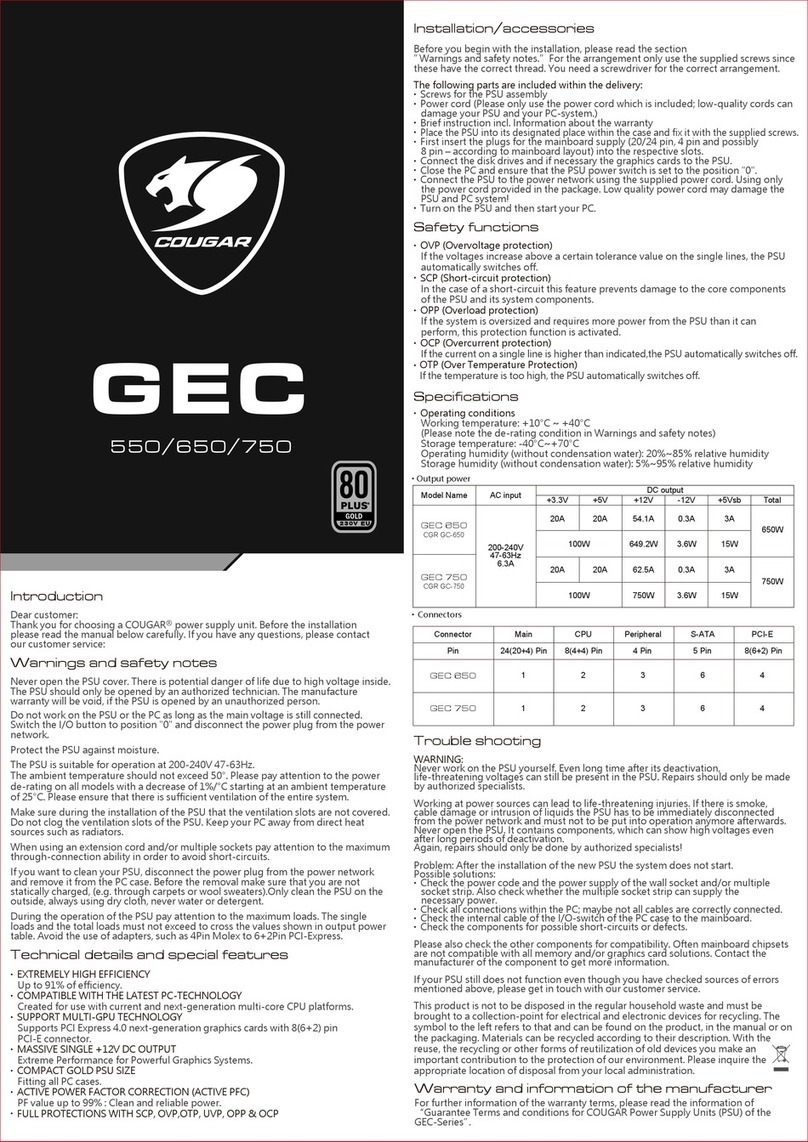
Wavetek 144 User manual

INSTRUCTION MANUAL
MODEL 144
HF SWEEP GENERATOR
THIS DOCUMENT CONTAINS INFORMATION PRO^
PRIETARY TO WAVETEK. THE INFORMATION IN
THIS DOCUMENT ISNOT TO BE USEDOR DUPLICATED
IN ANY MANNER WITHOUT THE PRIOR APPROVAL
IN WRITING OF WAVETEK.
VS^VVETEK
SAN DIEGO
9045 Balboa Ave., San Diego. Calif. 92123
P. 0. Box 651, San Diego, California 92112
Tel 714/279-2200 TWX 910-335-2007 REV L- 1/78

CONTENTS
Section One INTRODUCTION
Purpose of the Equipment
General Physical Description 1_1
Specifications 1_1
Accessories and Associated Equipment I.3
Section Two INSTALLATION AND OPERATION
Mechanical Installation 2-1
Electrical Installation 2-1
Operating Controls 2-2
Installation Checks 2-3
Operating Procedure 2-4
Section Three CIRCUIT DESCRIPTION
Simplified Block Diagram Analysis
Functional Block Diagram Analysis 3.0
Section Four MAINTENANCE
Access Instructions 4.I
Calibration Instructions 4_2
Corrective Maintenance 4.5
Section Five DIAGRAMS. ADDENDUMS, AND PARTS LISTS
Diagrams g.1
Addendums
Parts List 5^^
iii
12/70

MODEL 144
HE SWEEP GENERATOR
FREQ HZ
X10 X100
X.001
CAL
VERNIER
OUTPUT ATTEN
-3<MB
40dB -20c
MODE
GATED CONT SWP lOOiro ItOim SWP/6CV
OUT
TRIG
IN TRIG .TRIG SWP
SWP
HOLD
CONT. 100)J5
SWEEP WIDTH
TRIG LEVEL VARIABLE
Figure i—Model 144 HF Sweep Generator
SCOPE OF THIS MANUAL
This manual provides descriptive material and instructions for the installation, operation,
maintenance, and repair of this instrument. Wavetek's product improvement program ensures that
the latest electronic developments are incorporated in all Wavetek instruments by the addition
of circuit and component changes as rapidly as development and testing permit. Due to the time
required to document and print instruction manuals, it is not always possible to incorporate
the more recent changes in the released manual. In this case, data will be found on engineering
change sheets at the rear of the manual. If no change sheets are included, the manual is correct
as printed.
IV

SECTION I
INTRODUCTION
1.1
PURPOSE OF THE EQUIPMENT
The Model 144 HF Sweep Generator is aprecision 0.0005
Hz to 10 MHz source of sine, triangle, square, positive
pulse, and negative pulse waveforms. ..each with variable
amplitude, dc offset, and symmetry. Frequency range selec-
tion is provided in 10 decades, with avernier control per-
mitting adjustment of approximately 1% of the selected
range. Maximum output amplitude is 30 Vp-p into an
open circuit (15 Vp-p into 50 ohms) with a60 dB
calibrated step attenuator and a20 dB vernier attenuator
(80 dB overall) allowing signal levels as low as 1.5 mV p-p.
Both the output waveform and the dc offset are attenuated
by the 60 dB calibrated step attenuator.
Six operational modes (continuous, triggered, gated, con-
tinuous sweep, triggered sweep, and sweep and hold), plus
tone burst capability, are provided by the Model 144. The
main output can be internally swept over a1000:1 ratio
at sweep speeds from 10 /lxs to 100 seconds—or it can be
frequency modulated, dc programmed, or externally swept
over the 1000:1 ratio by applying an external control signal
to the front panel VCG IN connector. Asingle cycle of
output, or one full sweep of the output, can be obtained if
an external trigger is applied to the front panel TRIG IN
connector.
In addition to the 50S7 main output and aseparate rear
panel SYNC output, the Model 144 also has afront panel
SWP/GCV output. When the main output is not internally
swept,, the sawtooth output of the internal sweep generator
appears at the SWP/GCV OUT connector. When the main
output is internally swept, aGCV output proportional to
the instantaneous frequency of the main generator will
appear at the SWP/GCV OUT connector. This GCV output
(Generator-Controlled-Voltage) can be used to drive X-Y
recorders or the vertical and horizontal deflection circuits
of oscilloscopes, video monitors, etc.
Varying the triangle symmetry produces asawtooth or
"ramp" signal with arise or fall time as steep as 50 nano-
seconds at arecurring rate of 1MHz. Pulse outputs as
narrow as 50 nanoseconds, with repetition rates as high as
1MHz (on-off ratios as great as 19:1), can be generated
in either polarity. Even the sine wave symmetry may be
varied over this 1:19 to 19:1 range if desired. When the
output symmetry is not 1:1, the indicated output frequency
must be divided by approximately 10.
With this instrument it is possible to simultaneously pro-
gram or sweep the output frequency, select the output
symmetry desired, and manually vary the dc offset. This
capability, coupled with the variety of waveforms available
and precision output amplitude control, makes the Model
144 an extremely versatile instrument.
1.2 GENERAL PHYSICAL DESCRIPTION
Weighing approximately 9pounds (13 pounds when shipped)
the Model 144 is 8-1/2 inches wide, 5-% inches high, and
11-y2 inches deep. Housed in acompact, ruggedized,
portable case, the Model 144 is normally shipped with a
10-foot, 3-wire, detachable line cord and one copy of this
instruction manual.
1.3 SPECIFICATIONS
1.3.1 Versatility
WAVEFORMS
Selectable sine ^,square “"jj ,triangle ,positive
pulse ,and negative pulse u- .Symmetry of all out-
puts continuously adjustable from 1:19 to 19:1. Varying
triangle symmetry produces sawtooth /\ or /A out-
put. Separate SWP/GCV OUTput and separate SYNC
OUTput with variable symmetry as described below.
OPERATING FREQUENCY RANGE
0.0005 Hz to 10 MHz in the following ranges:
X.001 0.0005 Hz to .01 Hz
X.01 0.005 Hz to 0.1 Hz
X.1 0.05 Hz to 1Hz
XI 0.1 Hz to 10 Hz
X10 0.1 Hz to 100 Hz
X100 1Hz to 1kHz
X1K 10 Hz to 10 kHz
X10K 100 Hz to 100 kHz
X100K 1kHz to 1MHz
X1M 10 kHz to 10 MHz
Note: When symmetry control is used, indicated frequency is
divided by approximately 10.
1-1
12/70

MAIN OUTPUT
Sine, Square, triangle, positive pulse, and negative pulse;
selectable. Maximum output 30 Vp-p into open circuit;
(15 Vppulse) calibrated 15 Vp-p into 50f2. Precision
output attenuator calibrated in 10 dB steps to —60 dB
with 20 dB vernier for overall attenuation of —80 dB.
Output impedance is 5012. Short circuit current is 150 mA.
SYNC OUTPUT
Amplitude greater than 4Vp-p into open circuit; 2Vp-p
into 5012. Rise and fall times less than 50 ns. Square
waveform for symmetrical outputs, rectangular waveform
for pulse and ramp outputs. Sync pulse polarity opposite
that of output square wave.
DC Offset
Controlled manually by rear panel control. Adjustable range
±10 Vdc open circuit (±5 Vdc into 5012) with peak signal
and offset amplitude limited to ±15 Vdc into open circuit
(±7.5 Vdc into 5012). DC offset and output waveform
attenuated proportionately by 60 dB output attenuator.
SWP/GCV OUTPUT
SWP OUTput (0 to +5 Vfixed) when in Continuous,
Triggered, or Gated modes. GCV OUTput (0 to +5 V
maximum) proportional to frequency control settings when
in Continuous Sweep, Triggered Sweep, or Sweep and Hold
modes,
1.3.2
Operational Modes
Continuous
Operating as astandard VCG (voltage-controlled generator)
frequency of 5012 OUTput is determined by front panel
control settings in conjunction with VCG IN put signal.
Output of internal sweep generator appears at SWP/GCV
OUT connector.
Triggered
Only one complete cycle of output appears at 5012 OUT
connector for each pulse applied to TRIG IN connector.
Gated
Same as Triggered mode except that output oscillations
continue for duration of gating signal applied to TRIG IN
connector.
Continuous Sweep
Main generator is swept by internal sweep generator so that
frequency of 5012 OUTput Is swept from alow frequency
established by front panel frequency controls to ahigh
frequency determined by SWEEP WIDTH control setting.
Sweep rate is determined by SWEEP TIME and VARIABLE
controls. GCV OUTput (generator-controlled voltage) ap-
pears at SWP/GCV connector.
Triggered Sweep
Same as Continuous Sweep mode except that output is
swept only once for each pulse applied to TRIG IN con-
nector. During time between sweeps, main generator oscil-
lates at low frequency determined by frequency control
settings.
Sweep and Hold
Agated sweep in which the frequency output is held at
maximum at the end of each sweep for the duration of the
gate signal at the TRIG IN connector. Between gate signals,
the output is the low frequency determined by the frequency
control settings.
Tone Burst —Accomplished in Gated mode by connecting
ramp output of SWP/GCV OUTput to TRIG INput. Tone
burst rate, frequency, and duration can be independently
controlled in this configuration.
Trigger Input
1Vpeak into 10 kl2, dc coupled.
Sweep Time
10/zs to 100 seconds.
Sweep Width
Up to 1000: 1with single turn control.
1.3.3
Horizontal Precision
Frequency Dial Accuracy
0.01 Hz to 1MHz ±(1% of setting +1% of full scale) for
symmetrical waveforms,
1MHz to 10 MHz ±(2% of setting +2% of full scale) for
symmetrical waveforms.
Vernier
Permits frequency adjustment of approximately 1% of
range.
Time Symmetry
10 Hz to 100 kHz ±0.5%
0.01 Hz to 500 kHz ±10%
1.3.4
Voltage-Controlled Generator
VCG CONTROL RANGE
Up to 1000:1 frequency change with external voltage input.
Upper frequency is limited to maximum of selected range.
Required external signal for full voltage control is 5volts
with Input impedance of 5kl2.
1-2
8/73

VCG INPUT FREQUENCY
VCG Bandwidth 100 kHz
VCG Slew Rate 2% of range/microsecond
VCG LINEARITY
10 Hz to 100 kHz ±0.2%
0.001 Hz to 1MHz ±0.5%
1.3.5 Vertical Precision
SINE WAVE FREQUENCY RESPONSE
Amplitude change with frequency less than:
0.1 dB .to 100 kHz
0.2 dB to 1MHz
2.0 dB to 10 MHz
STEP ATTENUATOR ACCURACY
±0.25dB/10dB
STABILITY
Short term ±0.05% for 10 minutes
Long term ±0.25% for 24 hours
Percentages apply to amplitude, frequency, and dc offset.
AMPLITUDE SYMMETRY
All waveforms (except pulse) are symmetrical about ground
within ±1% of maximum peak-to-peak amplitude.
1.3.6 Purity
SINE WAVE DISTORTION
10 Hz to 100 kHz ..less than 0.5% (typically 0.25%)
100 kHz to 1MHz less than 1.0%
1MHz to 10 MHz ..all harmonics at least 30 dB down
TRIANGLE LINEARITY
0.002 Hz to 100 kHz greater than 99%
Linearity defined by best straight line method.
SQUARE WAVE RISE AND FALL TIME (terminated in
5012 load)
Less than 20 nanoseconds; limited to 500 V/microsecond.
TOTAL ABERRATIONS
Less than 5%.
1.X7 Environmental
TEMPERATURE
All specifications listed, except for stability, are for 25^C
±5°C. For operation from 0°C to 55°C, derate all specifi-
cations by afactor of 2.
1.3.8 Mechanical
DIMENSIONS
S-Va inches wide, 5-% inches high, ll-Va Inches deep.
WEIGHT
9pounds net, 13 pounds shipping.
POWER
105 Vto 125 Vor 200 Vto 250 V; 50 to 400 Hz. Less
than 40 watts.
1.4 ACCESSORIES AND ASSOCIATED EQUIPMENT
This instrument is normally shipped with a10-foot, 3-wire,
detachable line cord and acopy of this instruction manual.
The items listed below are compatible accessories and
associated equipment which may be helpful in the user's
installation.
RACK ADAPTER KIT Wavetek No. 130-602
ADAPTER CABLE(S),
SHIELDED BNC Female to BNC Female
BNC Female to BNC Male
BNC Female to Dual Banana
BNC Female to Dual Alligator
NOTE
Specifications apply from 1-10 on the fre-
quency dial.

2
SECTION
INSTALLATION AND OPERATION
2.1 MECHANICAL INSTALLATION
After unpacking the instrument, visually inspect all external
parts for possible damage to knobs, connectors, surface
areas, etc. If damage is discovered, file aclaim with the
carrier who transported the unit. The shipping container
and packing material should be saved in case reshipment
is required.
No mechanical installation is required when the instrument
is to be used as a portable bench top instrument. If a
rack-mounting configuration, or aRack Adapter Kit (see
paragraph 1.4), is provided, the unit may be mounted in a
standard 19-inch equipment rack. Instructions for attaching
the Rack Adapter Kit are provided with the kit.
2.2 ELECTRICAL INSTALLATION
2.2.1 Power Connection
Connect the ac line cord to the mating connector at the
rear of the unit.
NOTICE
Unless otherwise specified at the time of pur-
chase, all Wavetek instruments are shipped from
the factory with the power transformer con-
nected for operation on anominal 115-volt ac
line supply, and a3/8 amp 115 Vline fuse.
NOTICE
Conversion for 230-volt operation requires resetting a
switch at the rear of the instrument. To reset the 115/230
conversion switch (concealed by the rear panel) remove the
rear panel, set the slide switch to 230, and replace the
panel. Install afuse with arating of 3/16 amp at 230 volts.
2.2.2
Signal Connections
Use 5012 shielded cables equipped with female BNC con-
nectors to distribute all RF signals when connecting this
instrument to associated equipment.
GENERATOR MODE TRIGGER LEVEL SWEEP RATE SWEEP WIDTH
CONTROL CONTROL CONTROLS CONTROL OUTPUT
ATTENUATOR
REAR PANEL
CONTROLS
§SYMMETRY
DC OFFSET
SYNC OUTPUT
Figure 2-1 -Operating Controls
2-1
1/72

2.3 OPERATING CONTROLS
The operating controls and electrical connections for the
Model 144 are shown in Figure 2-1. The listing below
discusses each control and its function.
1. Frequency Range/Power Switch —This 11 position
switch selects the generator frequency range. The
extreme counter-clockwise position is the power off
position.
2. Frequency Dial —The main frequency control.
The setting on this dial multiplied by the frequency
range setting (above) equals the output frequency of
the generator. The frequency vernier (3) and the
symmetry control (11) also affect the generator fre-
quency. Note their effect in the listing below.
3. Frequency Vernier —This control allows precision
control over the output frequency. Acomplete turn
of this vernier is equivalent to approximately one half
of the smallest division on the main frequency dial.
When in the full clockwise position (CAL), the set-
tings on the main dial will be accurate.
4. Frequency Index —The scribe line indicates the fre-
quency dial setting. The index is illuminated when
the unit is on.
5. Waveform Selector —This selects the waveform that
appears at the 50L2 output connector. The waveforms
are sine ^,triangle \,square 'Xi .positive go-
ing pulse, and negative going pulse.
6. Amplitude Vernier —Avernier control of the output
amplitude. Maximum clockwise position gives the full
output amplitude of 30 Vpeak-to-peak into an open
circuit or 15 Vp-p into a50J2 load, except positive
and negative pulse which are 7.5 Vzero to peak ampli-
tude into 50£^ load. Counter-clockwise rotation will
continuously reduce the output amplitude. The con-
trol gives aminimum of 20 dB variation (10:1). This
control operates in conjunction with the output atten-
uator (9). For maximum amplitude output this vernier
must be full clockwise and the output attenuator in
the "0 dB" position.
7. 50f2 Out —This connector provides the selected
generator output function. The generator may oper-
ate into an open circuit providing 30 Vpeak-to-peak
maximum, or into a50fl load providing a 15 V
peak-to-peak output.
8. Sweep GCV Output —When the generator is in
continuous, trigger, or gated mode (control 12) this
output provides afixed 0to -i-5 Vsawtooth out-
put. The frequency of this output is controlled by
the sweep rate controls (11). When the generator is
in continuous Swp, Trig Swp, or Swp Hold modes
the output becomes the Generator Control Voltage
(GCV) that is proportional to frequency. The fre-
quency is controlled by the sweep rate controls (11)
and the amplitude is determined by the main fre-
quency dial, VCG input, and sweep width controls.
9. Output Attenuator —Attenuates the output from
0dB (15 Vp-p 5012 max) to -60 dB (15 mV p-p
into 5012) in six, 10 dB steps. The vernier (6) adds
an additional —20 dB, thus, amaximum of —80 dB
(1.5 mV p-p into 5012).
10. Sweep width control —Determines the amount of
sweep when in Cont Sweep, Trig Swp, or Swp
and Hold modes. Clockwise rotation increases sweep
width, counter clockwise rotation decreases sweep
width.
11. Sweep rate control —Determines the frequency of
the 144 ramp generator appearing at the SWP/GCV
OUT. The frequency of this generator is independent
of the frequency of the main generator. When in
any of the sweep modes, this ramp determines the
duration of the sweep cycle. The outer dial deter-
mines the frequency range and the vernier (inner)
dial provides afine adjustment. Note diat the outer
switch detent position is located between two time
ranges. With the vernier in the full clockwise position,
the sweep time is equal to the time to the right of
the detent setting. However, moving the vernier to
the full counterclockwise results in sweep time ap-
proximately 100 times the sweep time to the left of
the detent.
12. Trigger Level Control —Adjusts the sensitivity of the
Trigger Input Circuitry. When in the full counter
clockwise approximately —7.5 Vis required for
triggering. In the full clockwise position approxi-
mately -1-75. Vis required for triggering. At the mid
point, extremely low voltages will trigger the instru-
ment. By rotating the dial, it is possible to manually
trigger the generator. In the gated mode, the generator
will begin to run continuously as the control is
rotated past the mid-point in aclockwise direction.
13. Generator Mode Control —Selects the operating
mode of the main generator as follows:
a) Cont =Continuous Mode —The generator operates
at afixed frequency and runs continuously.
The SWP/GCV output is afixed 0to 5Vramp.
22
8/73

b) Trig =Trigger mode —The generator will give one
complete cycle of output for each pulse applied to
the TRIG IN connector. Since the SWP/GCV out-
put can be operated independently, it can be used
as aconvenient source. Manual triggering can be
accomplished by rotating the Trig Level Control
(13) from full CCW to full CW. The SWP/GCV
output is afixed 0to 5Vramp.
c) Gated == Gated Mode —Operates the same as
triggered mode except that the generator will con-
tinue to have output for die full time that the
signal at the TRIG IN connector exceeds the
GATING Level. See Trig Level (13}. The SWP/
GCV output is afixed 0to 5Vramp.
d| Cont Swp =Continuous with Sweep Mode —The
main generator operates continuously and repeti-
tively sweeps from the minimum to maximum
frequency as determined by the sweep controls.
In this mode as in the following two sweep modes,
the SWP/GCV output becomes the generator con-
trol voltage (GCV) which is proportional to the
instantaneous frequency of the generator.
e) Trig Swp =Triggered Sweep Mode —The main
generator oscillates at the start or low frequency
until atrigger signal is applied. The frequency
then sweeps to the maximum frequency as deter-
mined by sweep width and then returns to the
low frequency until another trigger is applied.
f) Swp Hold =Sweep and Hold Mode —The generator
operates the same as in triggered sweep mode
except that the output remains at the high fre-
quency after sweeping for the duration of the
gate pulse. When the gate pulse drops, the output
returns to the low frequency as set by the fre-
quency controls.
14. Trigger Input —DC coupled input with 10 k^2 input
impedance. The trigger level control adjusts the sensi-
tivity of the generator to this input signal.
15. VCG (Voltage Controlled Generator) Input —This
connector allows external control of frequency. With
0volts in, the generator output frequency is deter-
mined by the frequency range selected and the fre-
quency dial setting. Apositive VCG voltage will
increase this frequency, and anegative voltage wilt
decrease the frequency. Input impedance is 5kO:
16. Symmetry Control —This controls the time sym-
metry between the positive and negative portions of
the output waveform. In the full counter-clockwise
(detent) position, the control is disabled and the
output waveform has 1:1 symmetry (50-50 duty
cycle). Rotating the dial clockwise will vary the
symmetry from 1:19 through 19:1. Note: when the
symmetry is off the NORM (detent) position, the
output frequency is divided by approximately a
factor of 10. This allows aminimum pulse width
of 50 nanoseconds.
17. DC Offset —This rear panel control adjusts the
'amount of DC or baseline offset above or below
signal ground. The Detent position gives normal
symmetry and as the control is rotated from the
maximum negative offset through zero offset to
maximum positive offset.
18. Sync Out —This rear panel output provides asquare
or rectangular output at the same frequency of the
main generator. The output amplitude is approxi-
mately 2Vp-p into son. The phase relationship
between the sync output and the waveforms from
the son output is as shown in Figure 2-3.
2.4 INSTALLATION CHECKS
This paragraph outlines aquick checkout procedure to
determine if the instrument is operating properly. Field
calibration and checkout instructions are given in Section
4to determine compliance with electrical specifications.
If electrical deficiencies exist, refer to the warranty on the
back of the title page.
Use aTektronix Model 454 oscilloscope (or equivalent)
and a10 MHz Counter-Timer with 5-digit resolution
when performing these installation checks.
1.
After connecting the line cord to the ac line, set the
front panel controls and switches as follows:
FREQ HZ (switch) PWR OFF
FREQ DIAL (main dial) 10
WAVEFORM SELECTOR (switch) %
30 VP-P MAX (control) counterclockwise
SYMMETRY (rear panel switch/control) OFF
DC OFFSET (rear panel switch/control) OFF
OUTPUT ATTEN (switch) 0dB
MODE (switch) CONT
SWEEP TIME (switch) OFF
VARIABLE (control) clockwise
SWEEP WIDTH (control) clockwise
2. Connect the 50J2 OUT connector to the oscilloscope,
terminated in a50-ohm load.
3. Set FREQ HZ to X100. A1kHz sine wave with an
amplitude of less than 1.5 p-p should be displayed on
the oscilloscope.
23
8/73

4. Set the 30 VP-P MAX clockwise. The amplitude of
the displayed waveform should be 15 Vp-p.
5. Check the minimum and maximum amplitude of each
waveform using the WAVEFORM SELECTOR and
the 30 VP-P MAX control. Reset WAVEFORM SE-
LECTOR TO %.and 30 VP-P MAX to clockwise
position.
6. Observe the oscilloscope display and rotate the FREQ
DIAL clockwise to .1 setting. The sine wave fre-
quency should change from 1kHz to 10 Hz. Check
the range to range tracking accuracy with dial
setting at 10.
7. With FREQ HZ set to X100K and FREQ DIAL set
to .1, set VERNIER control fully counterclockwise.
The output frequency should be less than 1kHz.
8. Rotate SYMMETRY control slightly clockwise until
symmetry function is activated. The output square
wave should be unsymmetrical by aratio of approxi-
mately 1:19 and the frequency is divided by approxi-
mately 10. Continue rotating the SYMMETRY con-
trol through its entire range. The square wave sym-
metry should vary from 1:19 through 1:1 to 19:1 at
the full clockwise extreme.
9. Set 30 VP-P MAX fully counterclockwise and the
rear panel DC OFFSET clockwise. The baseline of the
output waveform should be approximately —5 volts.
Rotate DC OFFSET control from OFF to maximum
clockwise; the baseline should shift from —5 Vto
greater than -r5 V. Reset the control to OFF.
10. Set 30 VP-P MAX fully clockwise and rotate OUT-
PUT ATTEN switch through each position, observing
the oscilloscope display to check the output atten-
uation.
11. With SWEEP TIME set between 10 ms/1 ms and
VARIABLE set fully clockwise (1 ms sweep), the
SWP/GCV OUT waveform should be a1kHz saw-
tooth. Set VARIABLE fully counterclockwise; the
SWP/GCV OUT waveform should be less than 10 Hz.
12. Check the SWP/GCV OUT frequency in all positions
of the SWEEP TIME switch, at the clockwise and
counterclockwise ends of the VARIABLE control.
13. Using ashielded cable equipped with BNC connectors,
connect the SWP/GCV OUT connector to the TRIG
IN connector; and connect the scope to the 50fl
OUT connector. Set MODE switch to TRIG and
rotate TRIG LEVEL control while observing the
oscilloscope. One cycle of the selected ouqsut wave-
form should be displayed.
14. Set MODE switch to GATED and rotate TRIG LEV-
EL control while observing the oscilloscope. The
multiple cycles of the selected output waveform
should appear when the TRIG LEVEL control is
rotated toward the clockwise extreme and disappear
when the control is turned toward the counterclock-
wise extreme.
15. Set MODE switch to CONT SWP and set FREQ HZ
to XIK. Using a counter, set output frequency to
10 Hz with the FREQ DIAL. Set SWEEP WIDTH
fully clockwise and SWEEP TIME to lOOs/ls. Dis-
played output should sweep from 10 Hz to 10 kHz
at a1Hz rate.
16. Set MODE switch to TRIG SWP and rotate TRIG
LEVEL control while observing the oscilloscope. Dis-
played output should sweep once from 10 Hz to
10 kHz in 1second.
17. Set MODE switch to SWP HOLD and rotate TRIG
level control while observing the oscilloscope. When
TRIG LEVEL is fully counterclockwise, the 10 Hz
waveform should be observed. Rotate TRIG LEVEL
fully clockwise and the output should sweep from
10 Hz to 10kHz and hold as long as the TRIG LEVEL
is in this position.
18. Disconnect the cable from the TRIG IN connector,
and connect the SWP/GCV OUT connector to the
oscilloscope input. Set MODE switch to CONT and
SWEEP TIME to 10 ms/lms. The oscilloscope should
display a1kHz sawtooth waveform.
19. Set MODE switch to TRIG and then to GATED. The
same 1kHz sawtooth waveform should be present in
these modes.
20. Set MODE switch to CONT SWP, then TRIG SWP,
then SWP HOLD. The SWP/GCV OUT signal should
be aGCV signal proportional to the instantaneous
frequency of the main generator.
2.5 OPERATING PROCEDURE
No preparation for operation is required beyond completion
of the initial installation checks given in paragraph 2.4 of
2-4
12/70

this manual. It is recommended tiiat aone-half hour warm-
up period be allowed for the associated equipment to reach
astabilized opa-ating temperature, and for the Model 144
to attain stated accuracies.
2.5.1 Operation as a Function Generator
1. Properly terminate the 50S2 OUT connector.
2. Select desired output waveform using the WAVE-
FORM SELECTOR switch.
3. Set the generator mode switch to CONT.
4. Set FREQ HZ switch to desired multiplier.
5. Set FREQ DIAL to desired setting by aligning with
Index.
6. Set 30 VPPMAX and OUTPUT ATTEN switch for
desired output level and amplitude.
For retorence, the following table gives the approximate
output amplitude levels at attenuator settings. The output
levels of the positive and negative pulse waveforms are
one-half of these levels.
TABLE 2-1
Attenuator Position Peak-to-Ptok Output into 50£2 load.
Maximum
(Vernier full CW)
Minimum
OdB 15 volts 1.5 V
-lOdB 5volts 500 mV
-20 dB 1.5 volts 150 mV
-30 dB 500 mV 50 mV
-40 dB 150 mV 15 mV
-50 dB 50 mV 5mV
-60 dB 15 mV 1.5 mV
7.
With DC OFFSET set to 0detent position and SYM-
METRY control set to NORM, the output waveform
should be asymmetrical waveform oscillating around
azero dc reference point. (Except when in aposi-
tive or negative pulse position.)
8.
Select the polarity of dc offset desired and the
amount of offset using the rear panel control. If an
excessive amount of dc offset is used, waveform
clipping may be observed. The sum of peak wave-
form voltage and the dc offset cannot exceed the
maximum rated output of the generator. For ex-
ample, on the 0dB attenuator setting the maximum
,output is 15 Vpeak-to-peak or 7.5 Vpeak above
and below zero volts. Offset plus peak voltage cannot
exceed 7.5 V. See Figure 2-2.
0D.C. OFFSET
NEGATIVE DC OFFSET
Figure 2-2 -DC Offset Control
9.
Set SYMMETRY switch/control for desired sym-
metry or dissymmetry. The symmetry control can be
used to develop ramp waveforms with variable rise
fall ratios and pulse trains with variable duty cycle.
By using the sine wave with dissymmetry, controllable
sine distortion can be developed. Figure 2-3 shows
the effect of this control on output waveforms.
2-5
12/70(

SYMMETRY CONTROL AT NORM 2.5.2 Operation as a Voltage Controlled Generator
SYNC
TRIANGLE
SINE
SQUARE
POSITIVE PULSE
NEGATIVE PULSE
]
0
0-
SYNC
SYMMETRY CONTROL AT CW
0-
TRIANGLE
SINE
SQUARE
POSITIVE PULSE I[J-
I———
NEGATIVE PULSE ^
SYMMETRY CONTROL AT CCW
SYNC 0-1 P-
1
TRIANGLE
SINE
SQUARE
POSITIVE PULSE
“—'
NEGATIVE PULSE
|
Figure 2-3 -Waveform Phasing and Symmetry Control
The VCG input connector can be used to externally control
the frequency of the generator. If apositive voltage is
applied to the VCG input terminal the frequency will
increase from the dial setting. Anegative voltage will cause
the frequency to decrease from the dial setting. The VCG
range of the Model 144 is 1000: 1. On any range multiplier
setting, the frequency can be controlled from .01 xthe
multiplier to 10 xthe multiplier. The nomograph of
Figure 2-4 shows the characteristics of the VCG circuit.
Column Agives the frequency dial setting, column B, the
VCG voltage and column C, the resultant frequency of the
generator.
MAIN DIAL VCG IN 50S2 OUT
SETTING VOLTAGE FREQUENCY
Figure 2-4 -VCG Voltage-to-Frequency Nomograph
2-6

In example 1, the dial is set at 5and 0volts VCG input
voltage is applied. Extend astraight line from 5(dial
setting) through 0volts (VCG voltage). The result is an
output frequency of 5(multiplied by the range multiplier).
The generator can be made to free run in this mode at
certain settings of the trigger level control. By resetting
the trigger level control, normal gated operation can be
re-established.
In order to set the generator at .01 xthe range multiplier
(1/1000 of the range) the following procedure is to be
followed:
a) Using the frequency dial and acounter or oscillo-
scope, set the generator frequency to 0.1 xthe
range multiplier.
b) By rotating the vernier counter-clockwise, decrease
the frequency to .01 xthe range multiplier.
As can be seen from the nomograph, a+5 volt VCG input
vwll then cause the frequency to increase to the maximum
of 10 Xthe range (an increase from .01 to 10; i.e., 1000:1).
2.5.3 Operation as aTriggered Generator
1. Select the desired waveform using the waveform
selector switch.
2. Set the generator mode switch to trig.
3. Adjust the generator to the desired frequency (or
width) using the range switch and the main frequency
dial.
4. Apply asignal to the Trig In BNC.
Note: The SWP/GCV ouqiut may be used as atrigger
source. In this case the sweep time control determines
the repetition rate of the triggered output signal, and
the trigger level dial control sets the width, or dura-
tion, of the output signal.
2.5.4 Gated or Tone Burst Operation
With the generator adjusted as in trigger operation above,
change the mode control to the gated position. The gen-
erator output will then be aburst of signals. The duration
of the burst is adjustable by the trigger level control, refer
to Figure 2-5.
BURST REPETITION RATE
2.5.5
Operation as a Sweep Generator
Three sweep modes are available with the Model 144,
continuous with sweep, trigger with sweep and sweep and
hold. The operation of these modes can be visualized by
the graphs shown in Figure 2-6. These graphs plot the
output frequency of the generator as afunction of time
in the three different sweep modes.
GENERATOR
FREQUENCY
Figure 2-6 -Generator Sweep Modes
These modes together with the GCV output can be used,
to accurately adjust the sweep limits over apreselected
frequency range. The set-up procedure shown in Figure
2-7 utilizes an oscilloscope, however an X-Y recorder or a
counter could be used in asimilar manner.
2-7
1/74

OSCILLOSCOPE
Figure 2-7 -Set-Up Procedure
1. Select the waveform, amplitude and frequency range
desired.
2. Switch the generator to trig with sweep mode,
3. Adjust the START frequency to the desired value
with the main frequency dial.
4. With the generator connected to the oscilloscope as
shown in Figure 2-7, and the oscilloscope in the
external horizontal mode, adjust the horizontal posi-
tion so that the waveform is positioned on the left
reticle of the oscilloscope.
5. Turn the main frequency dial to the top frequency
desired, and adjust the horizontal gain of the oscillo-
scope so that the waveform is positioned on the
extreme right hand reticle, or any convenient reticle
of the screen.
6. Return the generator main dial to the start frequency
and switch the mode control to sweep and hold mode.
Adjust the sweep width control until the waveform
is positioned at the right hand reticle as selected in
step 5above.
Note: If the sweep width has no effect, it may be
necessary to manually trigger the generator by ro-
tating the trigger level control.
7.
Switch the generator to cont with sweep mode.
The frequency will now sweep between the START
frequency, selected by the main dial and the stop
frequency as adjusted by the sweep width.
If more detailed calibration of the oscilloscope horizontal
axis is required, the main dial can be used. By moving the
dial and noting the start point of the sweep, the hori-
zontal axis can be calibrated as afunction of frequency.
2.5.6 Floating Output
This instrument is shipped from the factory with the
signal ground floating above chassis ground, unless other-
wise specified at the time of purchase. If acommon signal/
cha^is ground is desired, perform the following modifi-
cation:
1. Disconnect the power cord, loosen the two captive
thumb screws on the rear panel, and remove the
rear panel.
2. Slide the dust cover out from the rear, loosen the
two screws on the rear plate and the two screws on
the power supply board (at bottom of chassis) and
remove the power supply board, flipping it over on
the main circuit board.
3. Solder one end of an insulated wire to the ground lugs
(green wires of the power connector) and push the
other end through the small opening on the main
circuit board.
4. Solder the other end of the insulated wire to the
ground terminal on the power supply board.
2-8
1/74

CIRCUIT
SECTION
DESCRIPTION
3.1 SIMPLIFIED BLOCK DIAGfV^ ANALYSIS
3.1.1 Main Generator
Refer to Figure 3-1, the Simplified Block Diagram, and
Figure 3-2, tiie Simplified Timing Diagram, when reading
this description. Paragraph 3.2 and its sub-paragraphs pro-
vide further descriptions of the functions of the basic
circuits in this instrument. This paragraph describes, briefly,
the major circuit elements and their relationship to one
another.
As shown in Figure 3-1, the VCG Summing Amplifier sums
the currents from the FREQ DIAL, VERNIER, and VCG
Figure 3-1 -Simplified Block Diagram
3-1

IN connector. The VCG Summing Amp is an inverting
amplifier whose output voltage is used to control apositive
current source and anegative current source. For sym-
metrical output waveforms, the currents from the two
current sources are equal and directly proportional to the
voltage of the VCG Summing Amplifier output. The Diode
Gate, which is controlled by the Hysteresis Switch, is used
to switch the positive current or the negative current to
the timing capacitor selected by the FREQ HZ selector. If
the positive current is switched into the timing capacitor,
die voltage across the capacitor will rise iinearly to generate
the triangle rise transition, if the current Is negative, the
voltage across the timing capacitor will fall linearly to
produce the fall transition.
The Triangle Amplifier is aunity gain amplifier whose out-
put is fed to the Hysteresis Switch as well as to the Sine
Converter. The Hysteresis Switch has two voltage limit
points (-M.25 Vand -1.25 V).
During the time the output voltage of the Triangle Ampli-
fier is rising, the output voltage of the Hysteresis Switch is
positive. But when the output voltage of the Triangle
Amplifier reaches -t-1.25 V, it triggers the Hysteresis Switch
causing the switch output to go negative. Once the control
+2.5V I—
C
-2.5V L_^_l
Figure 3-2 -Simplified Timing Diagram
voltage into the Diode Gate becomes negative, it will
switch die positive current out and switch the negative
current in to the timing capacitor, so that the voltage across
the capacitor will reverse, starting alinear decrease of the
waveform. When the decreasing voltage reaches —1.25 V,
the output of the Hysteresis Switch will switch back to
positive, reversing the process. This action generates the
triangle waveform as shown in Figure 3-2. Since the output
of the Hysteresis Switch is asquare wave, the result is
simultaneous generation of asquare wave and atriangle
wave at the same frequency.
The output frequency is determined by the magnitude of
the capacitor selected by the FREQ HZ selector and the
magnitude of the positive and negative current sources.
Since the current sources are linearly proportional to the
control voltage of the VCG circuit, the output frequency
will also be linearly proportional to the control voltage.
If the current of the negative current source is decreased
by 19 times, the fall time of the triangle will be 19 times
longer than the rise time of the triangle; resulting in an
unsymmetrical waveform and adivision of the frequency
by afactor of 10. Gradually increasing the current from
the negative current source and decreasing the current
from the positive current source in such away that the
period for the triangie to compiete one cycle remains
constant, the symmetry of the output waveform can be
continuously varied while the frequency is held constant.
The inverted output of the Hysteresis Switch is fed to the
Sync Amplifier and also the Square Wave Amplifier. The
Square Wave Amplifier cons;ists of ashaping circuit which
iimits the output swing to ±1.25 volts. For positive
pulse outputs, it limits the output voltage swing from
—1.25 Vto 0V; and for negative pulse outputs, it limits
the output swing from 0Vto +1 .25 V.
The output signai from the Triangle Amplifier is applied
to the Sine Converter, consisting of asine shaping circuit
and asine amplifier.
The sine, triangle, square, positive pulse, or negative
pulse is fed to the Output Amplifier through the WAVE-
FORM SELECTOR switch and the 30 VP-P MAX
control. The Output Amplifier is an inverting amplifier
whose output is fed into astep attenuator and then to the
output BNC connector.
The Attenuator consists of four pi attenuators, each having
a50-ohm input impedance and a50-ohm output imped-
ance. There is one —10 dB attenuator, one —20 dB
attenuator, and two —30 dB attenuators. By combining
them in six different arrangements, these four attenuators
provide 10 dB steps of attenuation; from 0dB to —60dB.
3-2

3.1.2 Sweep Generator and Trigger Logic
CONTINUOUS MODE
In this mode, both the Main Generator and the Sweep
Generator operate independently. As shown in Figure 3-3,
the Sweep Generator is apassive integrator with aVoltage
Controlled Current Source. The output of the Sawtooth
Amplifier changes the states of both the Peak and Zero
Detectors when either the peak or the zero limit is reached,
thus switching on and off the current source output. The
result of this charging and discharging of the timing capaci-
tor is acontinuous generation of asawtooth waveform.
The charging and discharging rate of the timing capacitor,
also the repetition rate of the sawtooth waveform, is pro-
portional to the amount of current fed into the capacitor
and the size of the capacitor. The amount of current
output is proportional to the controlling voltage and the
current programming resistor. Thus, the repetition rate is
controlled by the sweep time VARIABLE control R33
and the SWEEP TIME range selector switch.
The Current Source Switch provides ashunt path to signal
ground for the timing capacitor when the sawtooth wave-
form is in the negative slope region. Switching action is
activated by the Peak Detector and the Zero Detector
outputs. The Sawtooth Amplifier is anoninverting, high
input impedance, high slew rate amplifier providing low
output impedance and complete isolation for the passive
integrator.
The Peak and Zero Detectors accomplish detection of both
extremes of the sawtooth waveform. The outputs of these
two detectors, in conjunction with other transistor switches,
causes the Current Source Switch to place ashunt path
across the Timing Capacitor or remove the shunt path.
Thus, the operational loop is completed for the Continuous
Mode operation of the Sweep Generator.
TRIGGERED OR GATED MODES
Refer to Figure 3-4. In both the Triggered and the Gated
modes, the Main Generator and the Sweep Generator
operate independently.
Figure 3-3 —Sweep Generator, Continuous Mode
3-3

Figure 3-4 —Sweep Generator, Triggered or Gated Modes
When this instrument is in the TRIG mode and ready,
the Main Generator Diode Gate is switched off by the
Trigger/Gate Control, and the Timing Capacitor is dis-
charged through the shunt path. When atrigger signal
arrives at the Trigger/Gate Control, the control flip-flop
changes the state, opening the Diode Gate. Current flows
into the Timing Capacitor, allowing the passive integrator
to generate atriangle waveform. The control flip-flop is
reset by the square wave from the Sync Amplifier when
the proper phase triggers the flip-flop. The flip-flop output,
in conjunction with the level-shift circuit, closes the Diode
Gate. Thus, the single cycle generation of aselected wave-
form is accomplished.
When in the GATED mode, the output of the Trigger
Level Comparator/Squaring circuit is coupled directly to
the Trigger/Gate Control. The sequence of operation is
the same as that of the TRIG mode, except that one or
more cycles are generated for the duration of the trigger
(gate) signal applied to the TRIG IN connector.
SWEEP MODES
In the SWEEP modes of operation, athird input (the Sweep
Generator output) is added to the VCG Amplifiers through
the SWEEP WIDTH control. In the CONT SWP mode, the
Sweep Generator and the Main Generator run continuously.
In the TRIG SWP and SWP HOLD modes, the Main Genera-
tor runs continuously at the frequency set by the frequency
controls until atrigger or gate pulse appears at the TRIG IN
connector.
(a) Continuous Sweep Mode
Refer to Figure 3-5. In the CONT SWP mode, the basic
frequency of the Main Generator is set by the FREQ
3-4
8/73

Figure 3-5 -Sweep GEN, CONT SWP, TRIG SWP, &SWP HOLD modes
DIAL, the VERNIER, and the FREQ HZ selector. As the
Sweep Generator output starts moving positive, the fre-
quency increases linearly because the output of the Sweep
Generator is coupled through the SWEEP WIDTH control
to the first VCG Amplifier summing node. Maximum fre-
quency is determined by the basic frequency and the
setting of the SWEEP WIDTH control. It should be noted
that the maximum SWEEP WIDTH (fully clockwise) is
usable only when the basic frequency is set to less than
1/1 00th of the maximum frequency in the selected range.
The swept output waveform repeats for as long as the
MODE switch is set to CONT SWP. SWEEP TIME switch
and VARIABLE control determine the sweep repetition
rate.
(b) Triggered Sweep Mode
Refer to Figure 3-5. In the TRIG SWP mode, the Main
Generator runs continuously at the minimum frequency
set by the FREQ DIAL, VERNIER, and FREQ HZ selector.
The Sweep Generator is, initially, in astandby condition.
When an input trigger signal is applied at the TRIG IN con-
nector, the output of the Trigger Level Comparator/
Squaring circuit changes the state of the Trigger/Gate
Control circuit. The output of the Trigger Level Com-
parator/Squaring circuit is coupled through acapacitor to
release the Sweep Generator Clamp for asingle cycle.
Thus, asingle sweep of the Main Generator is accomplished.
The operation of the SWEEP WIDTH control is the same
as in the CONT SWP mode.
(c) Sweep and Hold Mode
The operation in this mode is similar to operation in the
triggered Sweep Mode except the output of the Trigger
Level Comparator/Squaring circuit is not coupled through
acapacitor, and the Sweep Generator Clamp is removed
for the duration of the trigger (or gate) signal. When the
gate signal drops, the Main Generator again runs continu-
ously at the frequency set by the frequency controls.
3-5
1/74

3.2 FUNCTIONAL BLOCK DIAGRAM ANALYSIS 3.2.1 Main Generator
As each functional block is described, refer to the appro- VCG AMPLIFIER AND CURRENT SOURCES
priate block diagram and, if necessary, the appropriate
portions of the schematic diagrams at the rear of this As shown in Figure 3-6, IC2 is connected as aSumming
manual. Amplifier to sum the VCG input current through R89,
the current from the FREQ DIAL R82, and the current
from the VERNIER control R90. 1C2 is an inverting
+15
Figure 3-6 —VCG Amplifier and Current Sources —15
3-6
8/73
Table of contents
Other Wavetek Portable Generator manuals
Wavetek
Wavetek 182A User manual

Wavetek
Wavetek 182A User manual
Wavetek
Wavetek 180 User manual
Wavetek
Wavetek 2500 User manual
Wavetek
Wavetek 148A User manual
Wavetek
Wavetek 188 User manual
Wavetek
Wavetek 1370 Installation instructions
Wavetek
Wavetek 3000 User manual
Wavetek
Wavetek 188 User manual
Wavetek
Wavetek 132 User manual

