GESTRA UNA45MAX User manual

Ball Float Steam Trap
UNA45MAX
UNA46MAX
UNA46AMAX
UNA47MAX
Original Installation Instructions
819401-04

Contents
Foreword............................................................................................................................... 3
Availability.............................................................................................................................................3
Formatting features in the document ......................................................................................................3
Safety................................................................................................................................... 3
Use for the intended purpose .................................................................................................................3
Basic safety notes .................................................................................................................................4
Information on property damage or malfunctions .....................................................................................4
Qualification of personnel.......................................................................................................................5
Protective gear......................................................................................................................................5
Typographic features of warning notes....................................................................................................5
Formatting features for warnings of property damage ..............................................................................5
Description............................................................................................................................ 6
Scope of supply and equipment specification ..........................................................................................6
Task and function................................................................................................................................10
Storing and transporting the equipment................................................................................... 11
Storing the equipment .........................................................................................................................11
Transporting the equipment .................................................................................................................11
Mounting and connecting the equipment ................................................................................. 12
Preparing installation ...........................................................................................................................12
Orientation of the equipment ................................................................................................................12
Connecting the equipment ...................................................................................................................14
Operation ............................................................................................................................ 17
After operation..................................................................................................................... 17
Removing external dirt deposits............................................................................................................18
Maintaining the equipment...................................................................................................................19
Servicing the equipment and installing spare parts ................................................................................23
Troubleshooting ................................................................................................................... 31
Retighten the stuffing-box packing........................................................................................................33
Putting the equipment out of operation.................................................................................... 34
Removing harmful substances..............................................................................................................34
Removing the equipment .....................................................................................................................34
Re-using equipment after storage.........................................................................................................35
Disposing of the equipment..................................................................................................................35
Technical data ..................................................................................................................... 36
Dimensions and weights ......................................................................................................................36
Pressure & temperature ratings............................................................................................................45
Declaration of Conformity – Standards and Directives ............................................................... 46

3
Foreword
This installation & operating manual will help you
use the following types of equipment safely and
efficiently for their intended purpose.
UNA 45 MAX
UNA 46 MAX
UNA 46A MAX
UNA 47 MAX
These steam traps will be called equipment in this
document.
This installation & operating manual is intended for
anyone commissioning, using, operating, servicing,
cleaning or disposing of this equipment and, in
particular, for professional after-sales service
technicians, qualified personnel and authorised and
trained staff.
All of these persons must read and understand the
content of this installation & operating manual.
Following the instructions given in this installation &
operating manual helps avoiding danger and
increases the reliability and service life of the
equipment. Please note that in addition to the
instructions given in this installation & operating
manual you must also observe all locally applicable
rules and regulations concerning the prevention of
accidents as well as approved safety guidelines for
good professional practice.
Availability
Keep this installation & operating manual together
with the plant documentation for future reference.
Make sure that this installation & operating manual
is available to the operator.
The installation & operating manual is part of the
equipment. Please hand over this installation &
operating manual when selling the equipment or
passing it on.
Formatting features in the
document
Certain text elements of this installation & operating
manual feature a specific typographic design. You
can easily distinguish the following text elements:
Standard text
Cross-reference
Listing
Sub-items in listings
Steps for action.
Here you will find additional useful
information and tips serving to assist you
in using the equipment to its fullest
potential.
Safety
Use for the intended purpose
The following ball float steam traps are designed to
discharge condensate from steam systems:
UNA 45 MAX
UNA 46 MAX
UNA 46A MAX
UNA 47 MAX
UNA 45 MAX models can also be used to discharge
condensate from compressed air.
UNA 46 MAX, UNA 46A MAX and UNA 47 MAX
models can also be used to discharge condensate
from other gases or gas mixtures.
The equipment must only be used within the
allowable pressure and temperature limits and only
if the chemical and corrosive influences on the
equipment are taken into account.
On type UNA 45, UNA 46 and UNA 46A models
with DUPLEX control unit and control membrane,
the superheated steam on the control membrane
must not exceed 5 K.
Correct use includes compliance with the
instructions given in this installation & operating
manual, in particular obedience to all safety
instructions.

4
Any other use of the equipment is considered to be
improper.
Note that the equipment is also used incorrectly if
the materials of the equipment are not suitable for
the fluid.
Basic safety notes
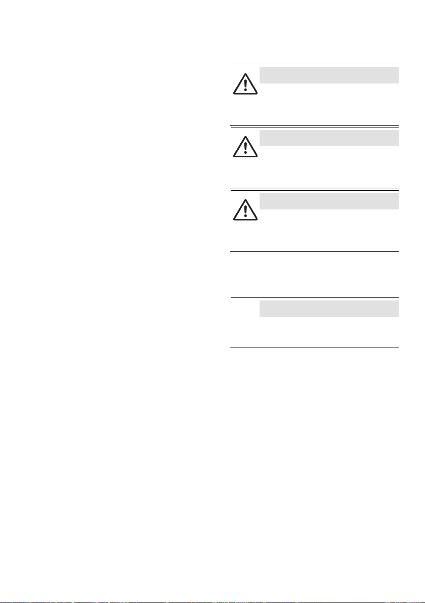
Risk of severe injuries
The equipment is under pressure during
operation and may be hot. Before carrying out
any work on the equipment make sure that the
following requirements are met:
The pipes must be depressurized (0 bar).
The fluid must be completely removed from
the pipes and the equipment.
During work on the equipment the
installation must be switched off and
protected against unauthorised or
unintended activation.
The pipes and the equipment must have
cooled down to room temperature (approx.
20 °C).
If the equipment is used in contaminated areas
there is a risk of severe injuries or death caused
by harmful substances in or on the equipment.
Before working on the equipment make sure
that it is completely decontaminated. Always
wear the protective clothing prescribed for
contaminated areas when working on the
equipment.
The equipment must only be used with fluids
that do not attack the material and the gaskets
and sealings of the equipment. Otherwise leaks
may occur and hot or toxic fluid could escape.
The equipment and its component parts must
only be mounted or removed by qualified
personnel. A qualified person must be
acquainted with and experienced in the
following:
Making pipe connections.
Selecting suitable lifting gear and
understanding the rules for its safe use.
Working with dangerous (contaminated, hot
or pressurized) fluids.
If the admissible temperature and pressure
limits are exceeded the equipment may be
destroyed and hot or pressurized fluid may
escape. Make sure that the equipment is only
operated within the admissible service range
and limits.
For more information on limits and pressure &
temperature ratings see name plate and the
section "
Technical Data
".
Risk of minor injuries
Sharp edges on internals present the danger of
cuts to hands. Always wear industrial gloves
when servicing the equipment.
If the equipment is inadequately supported
during installation, there is a risk of getting
crushed if it falls. Use the eyebolt to secure
lifting gear, if available. Secure the equipment
during installation so it cannot fall. Use the
eyebolt to do this, if available. Wear sturdy
safety boots.
Information on property damage
or malfunctions
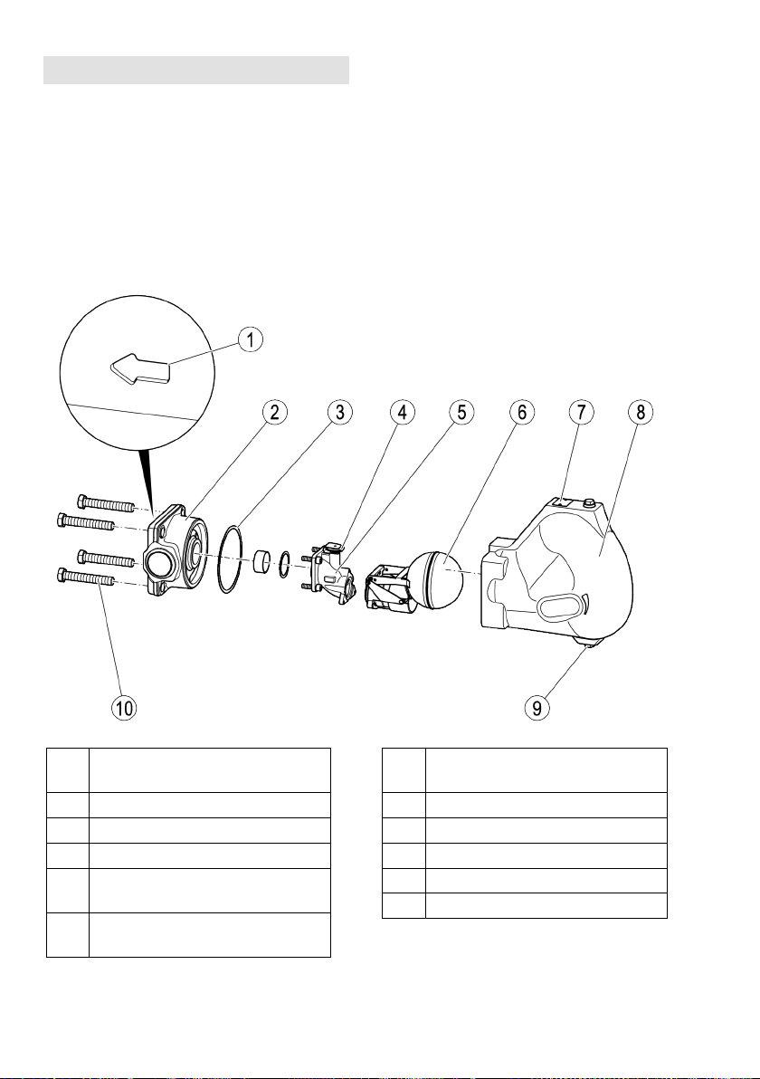
Malfunctions will occur if the equipment is
installed in a wrong position or with the flow
arrow pointing in the opposite direction of the
fluid flow. This may result in damage to the
equipment or the installation. Make sure that
the flow arrow on the equipment body matches
the indicated direction of the fluid flow in the
pipe.
If the material is unsuitable for the fluid,
increased wear may occur and fluid may
escape. Make sure that the material is suitable
for the fluid used in your installation.

5
Qualification of personnel
A qualified person must be acquainted with and
experienced in the following:
the pertinent on-site rules and regulations for
preventing fire and explosions as well as
industrial safety regulations
working on pressure equipment
making pipe connections
working with dangerous (hot or pressurized)
fluids
lifting and transporting loads
observing all notes and instructions in this
installation & operating manual and the
applicable documents
Protective gear
The operator must ensure that anyone working on
the equipment must wear the required protective
clothing and safety gear stipulated for the site of
installation. The protective clothing must be suitable
for the used media and must protect the wearer
against safety and health hazards associated with a
particular job to be carried out at the site of
installation. Protective clothing & equipment must
provide protection from potential hazards, in
particular from injuries to:
Head
Eyes
Body
Hand
Feet
Hearing
Note that this list is not exhaustive. The operator
must establish personal protective equipment
guidelines and specify any additional protective
gear that is required if the worker is exposed to a
specific risk at the site of installation.
Typographic features of warning
notes
DANGER
Notes with the heading DANGER warn
against imminent dangerous situations that
can lead to death or serious injuries.
WARNING
Notes with the heading WARNING warn
against possibly dangerous situations that
could lead to death or serious injuries.
CAUTION
Notes with the heading CAUTION warn
against dangerous situations that could
lead to minor or moderate injuries.
Formatting features for warnings
of property damage
Attention!
This information warns of a situation
leading to property damage.

6
Description
Scope of supply and equipment
specification
Scope of supply
Our equipment is delivered packed and ready for
assembly.
Equipment specification
Item
no.
Designation
1
Direction of flow arrow
2
Body
3
Body gasket
4
Capsule support with membrane
regulator capsule
5
Adapter (shown here: control unit
DUPLEX)
Item
no.
Designation
6
Control unit
7
Name plate
8
Cover (shown here: standard cover)
9
Drain with sealing plug
10
Hexagon-head cap screws (4 pcs.)

7
Optional extras
The following items are available as optional extra:
No.
Designation
11
Sealing plug
12 Manual vent valve with socket wrench
(socket wrench not shown)
The hole in the cover for the
manual vent
valve can also be used to connect an air
balance pipe.
13
Sightglass with glass water level gauge
for function check
1
No.
Designation
14
Sealing ring
15 Manual float-lifting lever with socket
wrench
16
Adapter with SIMPLEX control unit
17
Electrode cover with connection options
for electrodes NRG 16-19 or NRG 16-
27
1
1
Not for UNA 47 MAX
In equipment with control unit SIMPLEX the
hand
-vent valve is included as standard.

8
The different equipment versions allow you to adjust
the flow direction of the equipment to the flow
pattern of your installation. The flow arrow must
correspond to the direction of the fluid flow. The
following positions of installation are possible:
"v" for installation in vertical pipework with
downward flow
"hl" for flow from right to left (when viewed from
the body end)
"hr" for flow from left to right (when viewed from
the body end)
End connections
The equipment is available with the following end
connections:
Flanges
Screwed sockets
Socket-weld ends
Butt-weld ends via transition pieces
Screwed sockets are only available for
sizes DN 40 and 50.
Name plate/identification
The following items are indicated on the name
plate:
Manufacturer
Type designation
Design
Nominal size
Pressure rating
Design temperature
Design pressure
Max. service temperature
Max. admissible differential pressure
Mark (if required), e. g. CE, UKCA, EAC
Date of manufacturing
Material number
The following items are indicated on the equipment
body:
Material
Batch code
Direction of flow
The following items are indicated on the end
connections:
Flange size
Flange face type (RJ number)
Thread type

9
The limiting conditions and pressure &
temperature ratings specified in this
installation manual are applicable for
standard equipment. Note that these
values may differ for modified or
customized equipment.
All equipment specific values are indicated
on the nameplate.
Application of European Directives
Fluids
The equipment is designed for the following fluids
(in accordance with the EU Pressure Equipment
Directive or Pressure Equipment (Safety)
Regulations in the UK):
UNA 45 MAX
Fluids of group 2
UNA 46 MAX, UNA 46A MAX and UNA 47 MAX
Fluids of group 1
Fluids of group 2
Due consideration must be given to chemical and
corrosive influences.
Potentially explosive atmospheres
The equipment does not have its own potential
source of ignition (as per ATEX Directive). Please
pay attention to the following information:
When installed, static electricity may arise between
the equipment and the connected system.
When used in potentially explosive atmospheres,
the plant manufacturer or plant operator is
responsible for discharging or preventing possible
static charge.
If it is possible for medium to escape, e.g. through
actuating mechanisms or leaks in threaded joints,
the plant manufacturer or plant operator must take
this into consideration when dividing the area into
zones.

10
Task and function
Purpose
UNA 45 MAX, UNA 46 MAX, UNA 46A MAX and
UNA 47 MAX models are used to discharge
condensate from water vapour on steam-heated
consumers.
UNA 45 MAX models can also be used to discharge
condensate from compressed air.
UNA 46 MAX, UNA 46A MAX and UNA 47 MAX
models can also be used to discharge condensate
from other gases or gas mixtures.
Function
A ball float opens the orifice as a function of the
liquid level, thereby controlling the condensate
flowrate to be discharged. The max. discharge
capacity depends on the size of the fully open
orifice (O).
The float (6) rises with the liquid level and pulls the
nozzle stem (19) off the pilot valve (18), allowing a
small amount of fluid to flow through the pilot valve.
The fluid compresses the bellows of the control unit
and, as a consequence, the discharge orifice (20) is
completely uncovered.
Equipment with control unit SIMPLEX is particularly
suitable for cold condensates and superheated
steam.
Equipment with control unit DUPLEX may also be
used for air venting the installation. The control unit
DUPLEX consists of a float and a temperature
dependent air-venting facility. The air venting is
controlled by the membrane regulator. Equipment
with this type of control unit is particularly suitable
for saturated steam systems. Do not expose the
membrane regulator capsule of the DUPLEX control
unit to superheat conditions above 5 K.
The optional float-lifting lever allows you to lift the
float manually.
The optional hand-vent valve allows you to air vent
the pipe manually.

11
Storing and transporting the
equipment
Attention!
Equipment can be damaged if stored or
transported improperly.
Close all openings with the sealing
plugs or covers supplied with the
equipment or use similar sealing
covers.
Protect the equipment against
moisture and corrosive atmospheres.
Please contact the manufacturer if the
specified transport and/or storage
requirements cannot be met.
Storing the equipment
Please observe the following items when storing
the equipment:
Do not store the equipment for more than 12
months.
Use the supplied sealing plugs or other suitable
seal caps in order to seal off all openings of the
equipment.
Protect the sealing surfaces and contact areas
against mechanical damage.
Protect the equipment and all components
against hard shocks and impacts.
Store the equipment only in closed rooms that
meet the following environmental conditions:
Air humidity below 50 %, not condensing
Indoor air: clean, salt-free and non-corrosive
Temperature 5–40 °C.
Make sure that all these requirements are
always met when storing the equipment.
Please contact the manufacturer if you cannot
comply with the recommended storage
conditions.
Transporting the equipment
CAUTION
Do not drop the equipment. If it falls down
it may cause bruises and injuries.
To trans
port and mount the equipment
safely use suitable lifting gear.
Connect the noose strap of the lifting
gear to the body.
Provide sufficient support for the
equipment during transport and
installation.
Wear protective safety footwear.
Lightweight equipment may be transported and
mounted without using any lifting gear.
To lift equipment the weight of which exceeds
approx. 25 kg, you need the help of a second
person or suitable lifting gear.
Your physical strength and on-site regulations and
conditions determine what weight can be lifted and
if support is required.
Meet the requirements for storage also when
transporting the equipment.
Prior to transport seal off connections with
sealing plugs.
If you do not have the sealing plugs
supplied with the equipment use
appropriate seal caps to seal off the
connections.
For short distances (only a few metres) you can
transport the equipment unpacked.
When transporting the equipment over larger
distances use the original packaging.
If you do not have the original packaging use a
box that protects the equipment adequately
against corrosion and physical damage.
For a short period of time the equipment
may be transported even if the
temperature is below 0
°C, provided that
the equipment is completely empty and
dry.

12
Mounting and connecting the
equipment
Preparing installation
Take the equipment out of the transport
packaging.
Check the equipment for transport damage.
Contact the manufacturer if you detect any kind
of shipping damage.
When supplied by the factory, the connections may
be sealed off with sealing plugs.
Remove sealing plugs before mounting the
equipment.
Keep the sealing plugs and the packing for
further use.
DANGER
Personnel working on pipes are exposed to
safety risks and may suffer severe injuries,
poisoning or even loss of life.
Make sure that no hot or hazardous
fluid is in the equipment or the pipes.
Make sure that the pipes upstream
and
downstream of the equipment are
depressurised.
Make sure that the installation is
switched off and protected against
unauthorised or unintended activation.
Make sure that the equipment and the
pipes have cooled down to room
temperatures.
Wear protective clothing that is
suitable for the fluid and, if necessary,
wear protective gear.
For more information on suitable protective clothing
and safety gear refer to the safety data sheet of the
fluid in question.
Drain pipes until they are empty.
Switch the installation off and protect it against
unauthorised or unintended re-activation.
Orientation of the equipment
The different equipment versions allow you to adjust
the flow direction of the equipment to the flow
pattern of your installation. The following positions
of installation are possible:
with horizontal connections "hl" and "hr" for
installation in horizontal pipes
with vertical connections "v" for installation in
vertical pipework with downward flow
Attention!
Malfunctions may occur if the control unit
is installed incorrectly.
When installing the equipment make
sure that the name plate points
upwards and the float arm is free to
move up and down.
Make sure that the flow arrow on the
equipment body matches the direction
of flow in the pipe.
To avoid malfunctions make sure the following
requirements are met when mounting the
equipment:
The flow arrow on the equipment body must
match the fluid flow direction.
The name plate on the cover must point
upwards.
Contact the manufacturer if you want to mount
the equipment in a different position of
installation.

13
To change the position of installation remove the
adapter with the control unit attached to it.
In equipment with control unit DUPLEX the capsule
support is also attached to the adapter.
To remove the adapter proceed as follows:
Remove the cover from the body as described in
the section "
Removing cover
" from page 19.
Remove the four socket-head cap screws (21)
from the adapter (5).
Remove the adapter with the control unit from
the body (2).
Remove the adapter gasket (22).
For the disposal of the adapter gasket observe
the pertinent on-site regulations concerning
waste disposal.
Check all removed parts for signs of damage.
Replace all worn or damaged parts.
Clean all dirty parts.
Apply high-resistant lubricant to all threads,
bearing faces of screws, nuts and bolts.
The lubricant must have the same properties as
OKS®217.
Attention!
Equipment may leak if the gasket is
damaged.
Replace all gaskets that you loosen
during your work.
Use only new gaskets of the same
type.
Replace all gaskets with new ones of the same
type.
Turn the adapter (5) by 90° or 180° into the
desired position of installation.
Make sure that the float arm is free to move up
and down.
Put a new adapter gasket (22) onto the body.
Make sure that the adapter is not tilted or
skewed when fitted into the body (2).
Fix the adapter in place using the four socket-
head cap screws (21).
Tighten the socket-head cap screws with a
torque of 14 Nm.
Attach the cover to the body as described in the
section "
Mounting cover
" from page 22.

14
Connecting the equipment
DANGER
Incorrectly connected equipment can result
in accidents with extremely severe injuries
or death.
Make sure that only specialist
personnel connect the equipment to
the pipe.
Make sure that the direction of flow in
the pipe matches the flow direction
arrow on the equipment.
Make sure that the connected pipe
does not subject the body to any
stress (forces or torques) during
installation and operation.
Specialist personnel must have knowledge and
experience of the type of pipe connection used.
CAUTION
Do not drop the equipment. If it falls down
it may cause bruises and injuries.
To transport and mount the equipment
safely use suitable lifting gear.
Connect the noose strap of the lifting
gear to the body.
Provide sufficient support for the
equipment during transport and
installation.
Wear protective safety footwear.
Lightweight equipment may be transported and
mounted without using any lifting gear.
To lift equipment the weight of which exceeds
approx. 25 kg, you need the help of a second
person or suitable lifting gear.
Your physical strength and on-site regulations and
conditions determine what weight can be lifted and
if support is required.
Attention!
Equipment will be damaged if the end
connections are undersized.
Make sure that the connections are
strong and rigid enough t
o support the
weight of the equipment and to
withstand the forces that occur during
operation.
Consider space required for servicing the
equipment and/or exchanging components and
observe the necessary withdrawal distance to
remove the cover. For more information on the
required withdrawal distances see section
"
Dimensions and weights
" on page 36.
Some applications require that the
equipment is fitted with an air
-balance
pipe:
Equipment with control unit SIMPLEX MAX,
float traps for compressed air line drainage
and equipment installed in plants where
condensate is lifted upstream of the
equipment.
In this case connect the air balance pipe
to the bore on top of the cover.
Make sure that the pipe system of the plant is
clean.
Make sure that the equipment is free from
foreign matter.
Install the equipment in the desired, permitted
installation position.
Make sure that the pipes meet the following
requirements:

15
The layout of the pipelines must prevent the
formation of water pockets.
The pipeline must have a gradient so that the
condensate is free to fall towards the equipment
The cross section of the air balance pipe must
be at least DN 8 (¼ ") .
If the equipment is fitted with control unit
SIMPLEX, an air balance pipe must be
connected to the vent hole for the hand-vent
valve. The air balance pipe must have the
following end connection dimensions:
Standard cover and sightglass cover: G⅜ "
Cover with electrode connections: G¼ "
If one or more of the above mentioned
requirements cannot be met, please contact our
Technical Service or authorized agency in your
country.
Connect the end connections of the equipment
properly to the pipes.
If necessary, connect the air balance pipe to the
equipment as shown in the following drawing.
Make sure that the equipment is safely mounted
and that all connections are made correctly.

16
Mounting the measuring electrode
If the equipment has a cover with electrode
connections you can attach one or two measuring
electrodes of the following type:
To detect banking-up of condensate: NRG 16-
19 or NRG 16-27 installed on top of the body
(24)
To detect loss of water seal: NRG16–19 or
NRG16–27 installed at the side of the body (25)
If the equipment is fitted with a standard cover you
can fit the measuring electrode laterally.
The following tool is required for installation work:
Combination spanner to DIN 3113 form B:
Connection G¼ ”: A. F. 13
Connection G⅜ ”: A. F. 17
NRG16-19: A. F. 22
NRG16-27 (new): A. F. 27
NRG16-27 (old): A. F. 32
Torque spanner (US: wrench) 60-120 Nm to
DIN ISO 6789
Attention!
The measuring electrode might get
damaged if it is mounted incorrectly.
Do not insulate the equipment after
installation of the measuring
electrode.
Observe and follow all instructions
given in the installation & operating
manual for the measuring electrode.
To mount the measuring electrodes proceed as
follows:
Apply heat resistant lubricant to the threads and
the terminal box side of the measuring
electrode.
The lubricant must have the same properties as
OKS®217.
Use a suitable combination spanner to screw
the measuring electrode into the desired
connection (24 or 25) on the body.
Tighten the measuring electrode with a torque
of 75 Nm.
Connect the body to the pipework as described
in the previous section.
Attach an air balance pipe to the connection
G¼ ” (23).
Before mounting measuring electrodes
please note:
If a measuring electrode type NRG
16–27
is mounted on top of the body, only a
screwed union for a pipe with cross
section 8
mm will fit into the bore G¼”. If a
screwed union for a pipe with cross
section 10
mm were used, the hexagon
connection would press onto the
measuring electrode.

17
Operation
WARNING
Hot liquids and steam can cause scalding.
Wear protective clothing that is
suitable for the fluid and, if necessary,
wear protective gear.
Protective clothing and protective gear must protect
the whole body against contact with escaping hot
steam.
For more information on suitable protective clothing
and safety gear refer to the safety data sheet of the
fluid in question.
During operation you can undertake the following
work:
Open and close the optional hand-vent valve
Open and close the optional manual float-lifting
lever
To do this, use the socket spanner (stock code #
526110) supplied with the equipment.
The optional hand vent valve allows manual air
venting.
To air vent the equipment turn the hand-vent
valve (viewed from top) anticlockwise.
To close the hand-vent valve after air-venting
turn it clockwise.
Fasten the hand-vent valve hand tight.
The optional float-lifting lever allows the float to be
manually lifted irrespective of the liquid level. It can
be used to purge any dirt away from the seat area
and out of the equipment by opening the orifice and
draining the liquid.
The cast arrow on the body indicates the correct
direction of rotation.
To open the orifice turn the socket spanner from
the tip of the arrow towards the end of the
arrow.
To close the orifice turn the socket spanner
from the end of the arrow towards the tip of the
arrow.
After operation
DANGER
If fluid escapes personnel may suffer
severe injuries, poisoni
ng or even loss of
life.
After working on the equipment make
sure that all connections and valves
are tight.
Make sure that the gaskets of the
body are leakproof.
DANGER
Personnel working on pipes are exposed to
safety risks and may suffer severe injuries,
poisoning or even loss of life.
Make sure that no hot or hazardous
fluid is in the equipment or the pipes.
Make sure that the pipes upstream
and downstream of the equipment are
depressurised.
Make sure that the installation is
switched off and protected against
unauthorised or unintended activation.
Make
sure that the equipment and the
pipes have cooled down to room
temperatures.
Wear protective clothing that is
suitable for the fluid and, if necessary,
wear protective gear.
For more information on suitable protective clothing
and safety gear refer to the safety data sheet of the
fluid in question.

18
DANGER
If the equipment is used in contaminated
areas there is a risk of severe injuries or
death
caused by harmful substances in or
on the equipment.
Only qualified personnel are allowed to
perform work on contaminated
equipment.
Always wear the protective clothing
prescribed for contaminated areas
when working on the equipment.
Make sure that the equipment is
completely decontaminated before
carrying out any service work.
Follow the pertinent instructions for
handling the hazardous substances in
question.
Attention!
Frost damage may occur when the
installation is shut down.
Drain the equipment if ambient
temperatures below 0 °C (frost) are to
be expected.
Provide a device that collects any fluid that may
escape.
Remove the sealing plug (9) at the bottom of the
body.
Allow all liquid to escape and wait until the body
is completely empty.
To seal the drain hole screw in the sealing plug
and tighten it with a torque of 75 Nm.
Removing external dirt deposits
To remove dirt deposits rinse the equipment
with fresh water and wipe it with a clean, lint-
free cloth.
To remove any persistent residues use a
cleaning agent that is suitable for the material
and carefully wipe the equipment with a clean,
lint-free cloth.

19
Maintaining the equipment
For work on the equipment you will need the
following tools:
Combination spanner form B to DIN 3113, sizes
A. F. 17
A. F. 22
A. F. 24
A. F. 27
A. F. 32 for equipment with measuring
electrodes
Torque spanner to DIN ISO 6789
up to 10 Nm
10 – 60 Nm
60 – 120 Nm
120 – 300 Nm
Allen key to DIN ISO 2936, sizes
A. F. 5
A. F. 6
Screwdriver 5.5/125 to DIN 5265
Malfunctions may occur if the equipment is
used with different types of condensate:
The following condensates in particular
cause problems:
very oily condensates
condensates that resinify or become
gummy
condensates that recrystallize
condensates that contain solid matter.
In these cases check the equipment at
regular intervals for contamination and, if
necessary, remove dirt deposits.
To reduce con
tamination we recommend
installing a sedimentation vessel or a dirt
pocket arrangement upstream of the
equipment.
Normally you do not have to clean the internal parts
of the equipment.
To clean the equipment completely take off the
cover and remove the control unit.
The following drawings show equipment
type UNA
45 MAX with standard cover.
Removing cover
Remove the measuring electrode(s) if
mounted, before lifting off the cover.
Use a suitable combination spanner to
DIN 3113, form B, to remove the
measuring electrode.
Remove the four hexagon-head cap screws (10)
in the body.
Lift the cover (8) off the body (2).
Remove the body gasket (3).
For the disposal of the body gasket observe the
pertinent on-site regulations concerning waste
disposal.

20
Removing control unit
Remove the cover from the body as described in
the section "
Removing cover
" from page 19.
Remove the three socket-head cap screws (27).
Remove the control unit (6) together with the
orifice (28) from the adapter (5).
Remove the gasket (26) for the control unit.
For the disposal of the gaskets observe the
pertinent on-site regulations concerning waste
disposal.
Cleaning the equipment
Check the equipment at regular intervals for
contamination. The intervals depend on the amount
of dirt in the system. The operator must determine
the maintenance intervals.
Remove any parts that are dirty and cannot be
cleaned properly.
To clean the inside of the equipment proceed as
follows:
Remove the cover from the body as described in
the section "
Removing cover
" from page 19.
Remove the control unit as described in the
section "
Removing control unit
" on page 20.
To remove dirt deposits rinse the equipment
with fresh water and wipe it with a clean, lint-
free cloth.
To remove any persistent residues use a
cleaning agent that is suitable for the material
and carefully wipe the equipment with a clean,
lint-free cloth.
Secure the control unit to the body as described
in the section "
Mounting the control unit
" from
page 21.
Attach the cover to the body as described in the
section "
Mounting cover
" from page 22.
Cleaning and checking the membrane
regulator capsule
On models with DUPLEX control unit and control
membrane, clean the control membrane as follows.
The bimetallic vent is installed fixed in the
control unit. It cannot be removed.
Remove the cover from the body as described in
the section "
Removing cover
" from page 19.
Remove the control unit as described in the
section "
Removing control unit
" on page 20.
Remove the membrane regulator capsule as
described in section "
Exchanging the membrane
regulator capsule
" on page 29.
Clean the membrane regulator capsule with cold
clean water.
Use a depth gauge to check the dimension x of
the membrane regulator capsule as shown in
the following drawing.
The membrane regulator capsule is intact if
dimension x exceeds 4.0 mm.
Discard and replace defective membrane
regulator capsule with a new one.
Mount the membrane regulator capsule as
described in section "
Exchanging the membrane
regulator capsule
" on page 29.
This manual suits for next models
3
Table of contents
Other GESTRA Plumbing Product manuals
Popular Plumbing Product manuals by other brands

Fonteyn Spas
Fonteyn Spas Modern-2 Installation & owner's manual

Allen + Roth
Allen + Roth LWSG30VBR Assembly instructions

Tylo
Tylo SENSE COMBI installation guide

Luxart
Luxart VELERO VE341-LFDV Installation

VIGO
VIGO VGRA3618BLSF manual

American Standard
American Standard MONTERREY 6545 Series installation instructions

Artweger
Artweger Twinline 2 Operation and care guide

Omnires
Omnires SYSYW01BSB Installation and Maintenance

American Standard
American Standard 2474 Product user manual

Aquasanita
Aquasanita TERA 2763 installation instructions

noken
noken ZEN 100263141 N343120136 manual

Hans Grohe
Hans Grohe Talis E2 31687000 Instructions for use/assembly instructions