Follow instruction manual
The instruction manual is part of the product and an important element within the safety
concept.
• Read and follow instruction manual.
• Always keep instruction manual available for the product.
• Pass on instruction manual to all subsequent users of the product.
1. Intended use
The product is applicable for liquids with specific conductivity over 10 µS/cm. The
switching unit can sense the resistance between probes. Conductivity measurement is
suitable only for detecting the presence of liquid at a given level of the tank. This level
is represented by the length of the probe. The conductive switch is suitable for filling /
emptying control or level limit.
2. Safety and responsibility
In order to provide safety in the plant, the operator is responsible for the following
measures:
• Products may only be used for its intended purpose, see intended use
• Never use a damaged or defective product.
Immediately sort out damaged product.
• Make sure that the piping system has been installed professionally and serviced
regularly.
• Products and equipment shall only be installed by persons who have the required
training, knowledge and experience.
• Regularly train personnel in all relevant questions regarding locally applicable
regulations, safety at work, environmental protection especially for pressurised pipes.
The personnel is responsible for the following measures:
• Know, understand and follow the instruction manual and the advices therein.
3. Function
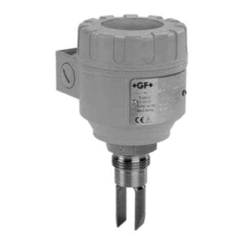
The level switch consists of a switching unit and the KLN-2 type probes. Probes are to
be connected to the 2281 probe socket head that can be screwed into the tank. lf the
material of the tank or its internal insulation is not conductive then a reference probe
should be used in addition to the one, two, three or four probe(s), if the material of the
tank is conductive, the tank can be used as a reference probe.
4. Technical Data
4.1 Technical Data of the switching unit
Probe Voltage 3.5 V AC
Probe current < 0.5 mA AC
Sensitivity Adjustable: 5 kΩ ... 100 kΩ
Max. cable capacity 800 nF
Response max. 400 ms
Setting accuracy (mech.) ± 5 %
Delay Adjustable: 0.5 ... 10 s
t1delay 1.5 s
Relay output 1x SPDT
Switching voltage 250 V AC1, 24 V DC
Switching current 8A AC1
Switching power 2500 vA AC1. 240 W DC
Electrical strength 3.75 kV
Mechanical life-span 3 x10⁷switches
Electrical life-span 0,7x10⁵ switches
Power supply Un 24V-240V AC/ DC
Voltage range allowed nominal voltage -15 %...+100 %
Power consumption max. 2.5 VA/ W
Ambient temperature -20°C ... +55°C
Electrical connection max. 2.5 mm2/ with insulation 1.5 mm2
Electrical protection Class II.
Ingress protection IP 20
Mechanical connection DIN EN 60715 rail
Mass 72 g
5. Dimensions
Switching unit: 2281-1-Relay Probe KLN-2XX
M20x1,5
1 ½BSP
M6
12180
33
43
12
C
38
38
Ø6
6. Installation
• Mount switching unit on DIN EN 60715 rail.
• Cut the KLN-2 type probes to the length required for level detection on site.
• Screw probes into the sockets.
• Tighten the probe with an M6 nut.
• Use separators at every 0.5 m for multiple probe devices to keep the probes apart.
7. Electrical Connection
lf the wall of the tank is conductive no reference probe is needed, ln this case terminal C
is to be connected to the tank. On multiple probe units E1 and E2 are marked with
1,,.4, the reference probe is marked with C. Admissible length of cable between signal
processor and probes depends on cable capacity and conductivity.
max
min
A1, A2 - power supply
C - reference probe
E1 - upper level probe
E2 - bottom level probe
15, 16, 18 - relay output
A1 A2
E1 E2
16 C
15 18
Un
Georg Fischer Piping Systems Ltd CH-8201 Schaffhausen
Phone +41(0)52 631 30 26 / info.ps@georgfischer.com /
www.gfps.com
GFDO 6353_4 (07.14)
© Georg Fischer Rohrleitungssysteme AG
CH-8201 Schaffhausen/Schweiz, 2014
Printed in Switzerland
Instruction manual
2281 Conductive multipoint switch
with single channel relay
GF Piping Systems


