manuals.online logo
Brands
  1. Home
  2. •
  3. Brands
  4. •
  5. Endress+Hauser
  6. •
  7. Switch
  8. •
  9. Endress+Hauser Liquiphant FTL33 IO-Link Technical specifications

Endress+Hauser Liquiphant FTL33 IO-Link Technical specifications

Other manuals for Liquiphant FTL33 IO-Link

2

Other Endress+Hauser Switch manuals

Endress+Hauser Soliphant T FTM20 User manual

Endress+Hauser

Endress+Hauser Soliphant T FTM20 User manual

Endress+Hauser FEC 22 User manual

Endress+Hauser

Endress+Hauser FEC 22 User manual

Endress+Hauser Liquicap M FTI51 User manual

Endress+Hauser

Endress+Hauser Liquicap M FTI51 User manual

Endress+Hauser Liquiphant M FTL50 User manual

Endress+Hauser

Endress+Hauser Liquiphant M FTL50 User manual

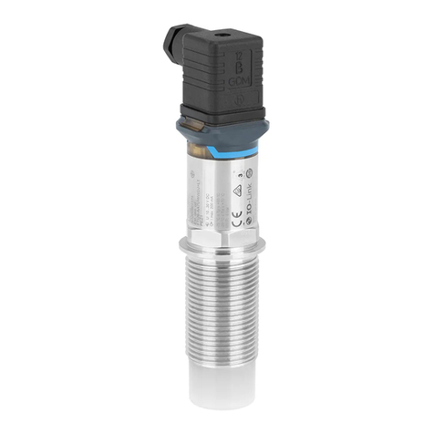
Endress+Hauser Liquiphant FTL33 IO-Link User manual

Endress+Hauser

Endress+Hauser Liquiphant FTL33 IO-Link User manual

Endress+Hauser Flowphant T DTT31 User manual

Endress+Hauser

Endress+Hauser Flowphant T DTT31 User manual

Endress+Hauser prosonic T FTU 230 User manual

Endress+Hauser

Endress+Hauser prosonic T FTU 230 User manual

Endress+Hauser Solicap M FTI55 User manual

Endress+Hauser

Endress+Hauser Solicap M FTI55 User manual

Endress+Hauser Thermophant T TTR 31 User manual

Endress+Hauser

Endress+Hauser Thermophant T TTR 31 User manual

Endress+Hauser Liquipoint T FTW31 User manual

Endress+Hauser

Endress+Hauser Liquipoint T FTW31 User manual

Endress+Hauser Liquiphant M FTL50 Installation instructions

Endress+Hauser

Endress+Hauser Liquiphant M FTL50 Installation instructions

Endress+Hauser Liquiphant FTL51B Technical specifications

Endress+Hauser

Endress+Hauser Liquiphant FTL51B Technical specifications

Endress+Hauser Liquipoint T FTW32 User manual

Endress+Hauser

Endress+Hauser Liquipoint T FTW32 User manual

Endress+Hauser nivotester FTC 420 User manual

Endress+Hauser

Endress+Hauser nivotester FTC 420 User manual

Endress+Hauser Liquiphant FTL64 User manual

Endress+Hauser

Endress+Hauser Liquiphant FTL64 User manual

Endress+Hauser Liquiphant FTL51B User manual

Endress+Hauser

Endress+Hauser Liquiphant FTL51B User manual

Endress+Hauser MPC2000 MPC2 User manual

Endress+Hauser

Endress+Hauser MPC2000 MPC2 User manual

Endress+Hauser Liquiphant FTL31 User manual

Endress+Hauser

Endress+Hauser Liquiphant FTL31 User manual

Endress+Hauser Proline Promag 55 User manual

Endress+Hauser

Endress+Hauser Proline Promag 55 User manual

Endress+Hauser Soliphant M FTM52 User manual

Endress+Hauser

Endress+Hauser Soliphant M FTM52 User manual

Endress+Hauser OFTE20 User manual

Endress+Hauser

Endress+Hauser OFTE20 User manual

Endress+Hauser Liquiphant FTL64 Technical specifications

Endress+Hauser

Endress+Hauser Liquiphant FTL64 Technical specifications

Endress+Hauser Liquiphant FTL51B Technical specifications

Endress+Hauser

Endress+Hauser Liquiphant FTL51B Technical specifications

Endress+Hauser Nivotester FTC325 User manual

Endress+Hauser

Endress+Hauser Nivotester FTC325 User manual

Popular Switch manuals by other brands

SMC Networks SMC6224M Technical specifications

SMC Networks

SMC Networks SMC6224M Technical specifications

Aeotec ZWA003-S operating manual

Aeotec

Aeotec ZWA003-S operating manual

TRENDnet TK-209i Quick installation guide

TRENDnet

TRENDnet TK-209i Quick installation guide

Planet FGSW-2022VHP user manual

Planet

Planet FGSW-2022VHP user manual

Avocent AutoView 2000  AV2000BC AV2000BC Installer/user guide

Avocent

Avocent AutoView 2000 AV2000BC AV2000BC Installer/user guide

Moxa Technologies PT-7728 Series user manual

Moxa Technologies

Moxa Technologies PT-7728 Series user manual

Intos Electronic inLine 35392I operating instructions

Intos Electronic

Intos Electronic inLine 35392I operating instructions

Cisco Catalyst 3560-X-24T Technical specifications

Cisco

Cisco Catalyst 3560-X-24T Technical specifications

Asante IntraCore IC3648 Specifications

Asante

Asante IntraCore IC3648 Specifications

Siemens SIRIUS 3SE7310-1AE Series Original operating instructions

Siemens

Siemens SIRIUS 3SE7310-1AE Series Original operating instructions

Edge-Core DCS520 quick start guide

Edge-Core

Edge-Core DCS520 quick start guide

RGBLE S00203 user manual

RGBLE

RGBLE S00203 user manual

Thrustmaster FLIGHT SIMULATOR X quick guide

Thrustmaster

Thrustmaster FLIGHT SIMULATOR X quick guide

Southwire SURGE GUARD 41390 RVC troubleshooting guide

Southwire

Southwire SURGE GUARD 41390 RVC troubleshooting guide

Buhler Nivotemp NT 61 Brief instructions

Buhler

Buhler Nivotemp NT 61 Brief instructions

Kramer VS-41HDCP user manual

Kramer

Kramer VS-41HDCP user manual

Techly IDATA AU-270 user manual

Techly

Techly IDATA AU-270 user manual

Belkin F1U109 user manual

Belkin

Belkin F1U109 user manual

manuals.online logo
manuals.online logoBrands
  • About & Mission
  • Contact us
  • Privacy Policy
  • Terms and Conditions

Copyright 2025 Manuals.Online. All Rights Reserved.

These Brief Operating Instructions are not a substitute for the Operating Instructions pertaining to the device.
Detailed information is provided in the Operating Instructions and other documentation.
Available for all device versions via:
• Internet: www.endress.com/deviceviewer
• Smartphone/tablet: Endress+Hauser Operations app
Basic safety instructions
Requirements for the personnel
The personnel performing installation, commissioning, diagnostics and
maintenance must satisfy the following requirements:
• Trained, qualified specialists: must have a relevant qualification for this
specific function and task
• Are authorized by the plant owner/operator
• Are familiar with federal/national regulations
• Before starting work: read and understand the instructions in the manual and
supplementary documentation as well as the certificates (depending on the
application)
• Follow instructions and comply with basic conditions
Intended use
The device described in this manual may be used only as a point level switch for
liquids. The device is suitable for use in areas with strict hygiene requirements.
Incorrect use of the device may pose a hazard.
To ensure that the device remains in proper condition for the operation time:
• Use the device only for media to which the wetted materials have an adequate
level of resistance
• Comply with the limit values, see the "Technical data" section of the Operating
Instructions
Operational safety
Danger of injury!
‣Operate the device only if it is in proper technical condition, free from errors
and faults.
‣The operator is responsible for the interference-free operation of the device.
Mounting
The mounting process is illustrated in the following section on the basis of
sample configurations. For detailed information, see the Operating
Instructions.
Mounting requirements
L1
L2
L3
L4
AB
2
1
32 mm
32 mm
3 3
ADevice with weld-in adapter
B Device in customer socket
1 Flat seal
2 Weld-in adapter
3 Tuning fork
L1 With G 1" thread: 66,4 mm (2,61 in) / With G ¾" thread: 63,9 mm (2,52 in)
L2 With G 1" thread: 48,0 mm (1,89 in) / With G ¾" thread: 38,0 mm (1,5 in)
L3 With G 1" thread: 66,4 mm (2,61 in)
L4 With G 1“ thread:47,9 mm (1,8 in)
Installation is possible in any position in a vessel, pipe or tank under the
following conditions:
• When installed horizontally in a vessel, the tuning fork may be located in an
installation socket only if liquids with low viscosity (< 2 000 mPa⋅s) are used.
• Minimum diameter of installation socket: 50 mm (2.0 in)
• Select a maximum length for the installation socket that enables the tuning
fork to project freely into the vessel.
• Ensure that there is sufficient distance between the expected buildup on the
tank wall and the fork. Recommended distance from wall ≥10 mm (0.39 in).
Important process conditions
Pressure and temperature (maximum):
• With weld-in adapter
• +25 bar (+362 psi) at +150 °C (+302 °F)
• +40 bar (+580 psi) at +100 °C (+212 °F)
• In customer socket
+40 bar (+580 psi) at +150 °C (+302 °F)
Operating altitude:
Up to 2 000 m (6 600 ft) above sea level
In the case of seals used at the customer site, pay attention to the
temperature and pressure specifications.
Products Solutions Services
Brief Operating Instructions
Liquiphant FTL33
Point level switch for liquids in the food industry
KA01619F/00/EN/01.22-00
71588702
2022-10-03
*71588702*
71588702
KA01619F
2 Endress+Hauser
Mounting the device
An open-ended wrench (32 mm) is required for mounting.
For the NTP thread (ANSI B 1.20.1): use sealing material (PTFE) if
necessary.
For the weld-in adapter with a flush-mount seal: remove the supplied flat
seal (1) from the thread.
For the weld-in adapter with leakage hole: make sure the leakage hole
points downwards.
Aligning the tuning fork
The markings for the material specification (e.g. 316L) or the thread
designation (e.g. G 3/4") on the device are aligned with the opening of the
tuning fork and therefore aid orientation.
G 3/4
316L
G 3/4
316L
A0047633
 1 In the pipe: align the opening of the tuning fork parallel to the flow direction in such a
way that the liquid can flow unhindered between the two tuning fork elements.
A0050834
 2 For horizontal installation in a vessel: align the tuning fork in such a way that both
tuning fork elements are simultaneously covered with liquid.
‣Fix the device with a maximum torque of 30 Nm (22 lbf ft). Also pay
attention to the alignment of the tuning fork when doing so.
Electrical connection
The connection with the M12 plug is presented in the following section. For
other connection options, see the Operating Instructions.
In accordance with IEC/EN61010 a suitable circuit breaker must be
provided for the device.
Power supply
Electronic version Supply voltage Power consumption Current consumption
3-wire DC-PNP 10 to 30 V DC < 975 mW < 15 mA
2-wire AC/DC 20 to 253 V < 850 mW < 3.8 mA
Reverse polarity
protection
2-wire AC/DC
• AC mode: the device has reverse polarity protection.
• DC mode: in the event of reverse polarity the maximum
safety mode is always detected. Check the wiring and
perform a function check before commissioning. The device
is not damaged in the event of reverse polarity.
3-wire DC-PNP
Integrated. In the event of reverse polarity, the device is
deactivated automatically.
Connection with M12 plug
Maximum safety
Terminal assignment MAX output Yellow LED
2
1
3
4
L–
L+
0.5A
K
A0051048
12
A0045069
2
1
A0045070
Minimum safety
Terminal assignment MIN output Yellow LED
2
1
3
4
L–
L+
0.5A
K
A0051049
4
11
A0045076
14
A0045075
LED indicator
2
3
1
A0047656
1 LED is green: the device is operational
2 LED is yellow: tuning fork is covered by liquid
3 LED is red: warning/maintenance required (LED flashing) or fault/device failure (LED is
lit)
On the metal housing cover (IP69), there is no external signaling via LEDs.