E.J.A. Engineering Guardmaster Centaur User manual


SPECIALISTS IN MACHINERY SAFETY
FOOT OPERATED SWITCHES
FUSS-SCHALTER
PEDALE DE COMMANDE AVEC CONTACTS ELECTRIQUES
(c) RETAIN THESE INSTRUCTIONS
Installation must be in accordance with the following steps
and must be carried out by suitably competent personnel.
Ensure that the Centaur switch is located in a comfortable
and safe position free from obstruction, debris or waste
from any machine in the locality.
Einbauanleitung
(b) Installation Instructions Notice D'installation
Deutsch / Français
(a) Description
The Centaur foot-operated switch is for use in
direct or general control of circuits where
either a momentary or latching pedal action is
required. With momentary pedal action the
pedal is depressed to the run position and
allows the power to the machine. When the
pedal is released the power is issolated and
the machine stops. With latching pedal
action the pedal is depressed to the run
position and allows the power to the
machine. The pedal can now be released and
the power will remain on until a further
depresion of the pedal releases the switch
and isolates the power.
Beschreibung
Der Fußschalter Centaur wird in direkten oder
allgemeinen Steuerkreisen eingesetzt, wenn
entweder eine Tast- oder eine Rast-Funktion
benötigt wird. Bei der Tast-Ausführung wird
das Pedal bis zur EIN-Stellung durchgedrückt,
wodurch die Maschine aktiviert wird. Beim
Loslassen des Pedals wird die Maschine
abgeschaltet. Bei der Rast-Ausführung wird
das Pedal ebenfalls bis zur EIN-Stellung
durchgedrückt, wodurch die Maschine aktiviert
wird. Beim Loslassen des Pedals bleibt die
Maschine angeschaltet. Erst bei erneutem
Drücken des Pedals wird die Maschine
abgeschaltet (Fortschrittschaltung).
Description
La pédale de commande Centaur est utilisée
pour la commande directe des moteurs ou des
circuits généraux de contrôle. Elle est
disponible en version à action momentanée ou,
à action par accrochage de la pédale. La
version à action momentanée permet de
démarrer la machine par une simple pression
du pied. Le retrait du pied coupe l’alimentation
et arrête la machine. La version à accrochage
permet le maintien de la marche de la machine
dès la première impulsion du pied, même si le
pied est par la suite retiré. Elle maintiendra la
machine en marche jusqu'à la pression
suivante qui décrochera la pédale et ouvrira
les circuits d’alimentation de la machine.
Centaur
1(d) Centaur for use in direct control or general control circuits
DIESE ANLEITUNG AUFBEWAHREN
Die Installation ist entsprechend den folgenden Schritten von
qualifiziertem Elektro-Personal durchzuführen. Sicherstellen, daß
der Schalter an einer geeigneten und sicheren Stelle ohne
Behinderungen, Schmutz oder Abfälle montiert wird.
INSTRUCTIONS A RETENIR
L’installation devra suivre les étapes suivantes et devra
être effectuée par du personnel formé et compétent.
Assurez vous que chaque pédale est installée de manière
ergonomique pour l’opérateur, à un endroit libre
d’accès, non obstrué par des débris ou objets.
Ø6mm
219mm
25mm
M6 (x3)
50mm
M4 (x2)
(e) Foot switch without pedal cover
Part no. 38003, 2N/O, latching, direct control of motor and
general control circuit
Part no. 38001, 2N/O, momentary, direct control of motor and
general control circuit
Part no. 38009, 1N/O+1N/C, momentary, general contol circuit
(f) Foot switch without pedal cover
Part no. 38005, 2N/O, latching, direct control of motor and
general control circuit
Part no. 38007, 2N/O, momentary, direct control of motor and
general control circuit
Part no. 38013, 1N/O+1N/C, latching, general contol circuit
Part no. 38011, 1N/O+1N/C, momentary, general contol circuit
Part no. 38019, 2N/O+2N/C, momentary, general contol circuit
M4 (x2)
(g) 2 x M20
Conduit entry
1N/O+1N/C
2N/O+2N/C
Ensure switch is securely fixed on a flat surface
(h)
11
12
23
24
2N/O
1
2
3
4
11
12
23
24
31
32
43
44
(i) Contact arrangements
(j) Ensure that the wiring is suitably
protected and does not pose a
tripping hazard.
(d) Centaur in direkten oder allgemeinen Steuerkreisen
Pédale Centaur utilisée pour la commande directe des
moteurs ou des circuits généraux de contrôle
(e) Fußschalter ohne Abdeckhaube
Bestell-Nr. 38003, 2 Schließer, rastend, direkte
Ansteuerung von Motoren oder allgemeinen Steuerkreisen
Bestell-Nr. 38001, 2 Schließer, tastend, direkte
Ansteuerung von Motoren oder allgemeinen Steuerkreisen
Bestell-Nr. 38009, 1 Schließer + 1 Öffner, tastend,
direkte Ansteuerung von allgemeinen Steuerkreisen
Pédale de commande sans couvercle
Ref N
°
38003, 2 N/O, accrochage, commande directe
des moteurs ou des circuits généraux de contrôle
Ref N
°
38001, 2 N/O, momentanée, commande directe
des moteurs ou des circuits généraux de contrôle
Ref N
°
38009, 1N/O+1N/C, momentanée, commande
directe des circuits généraux de contrôle
(f) Fußschalter mit Abdeckhaube
Bestell-Nr. 38005, 2 Schließer, rastend, direkte
Ansteuerung von Motoren oder allgemeinen Steuerkreisen
Bestell-Nr. 38007, 2 Schließer, tastend, direkte
Ansteuerung von Motoren oder allgemeinen Steuerkreisen
Bestell-Nr. 38013, 1 Schließer + 1 Öffner, rastend,
direkte Ansteuerung von allgemeinen Steuerkreisen
Bestell-Nr. 38011, 1 Schließer + 1 Öffner, tastend,
direkte Ansteuerung von allgemeinen Steuerkreisen
Bestell-Nr. 38019, 2 Schließer + 2 Öffner, tastend,
direkte Ansteuerung von allgemeinen Steuerkreisen
Pédale de commande avec couvercle
Ref N
°
38005, 2 N/O, accrochage, commande directe
des moteurs ou des circuits généraux de contrôle
Ref N
°
38007, 2 N/O, momentanée, commande directe
des moteurs ou des circuits généraux de contrôle
Ref N
°
38013, 1N/O+1N/C, accrochage, commande
directe des circuits généraux de contrôle
Ref N
°
38011, 1N/O+1N/C, momentanée, commande
directe des circuits généraux de contrôle
Ref N
°
38019, 2N/O+2N/C, momentanée, commande
directe des circuits généraux de contrôle
(g) 2 x M20 Leitungseinführungen
Sorties câbles : 2 X M20
(Pour la France presse-étoupe fourni)
(h) Sicherstellen, daß Fußschalter gut auf
ebener Unterfläche befestigt ist.
Assurez vous que la pédale est fixée
sur un sol plat
(i) Kontaktkonfigurationen
Présentation des contacts
(j) Sicherstellen, daß die Verdrahtung geeignet
geschützt ist und keine Gefährdung darstellt.
Assurez-vous que les câblages sont bien
protégés et qu’il ne sont pas sujets à un
risque de court-circuit

2(k)
After wiring replace the lid. Before allowing routine machine use, ensure machine operates and stops when the foot switch is operated according to instructions.
The foot switch and system should be subject to routine inspection to ensure that the conditions referred to in these instructions are maintained.
Nach Anschließen Deckel aufsetzen. Vor normalen Maschinenbetrieb überprüfen, ob Maschine bei Betätigen des Fußschalters korrekt startet und stoppt.
Fußschalter und Installation sollten regelmäßig überprüft werden, um sicherzustellen, daß die hier genannten Bedingungen erfüllt werden.
Replacer le capot après câblage. Avant l’utilisation en production de la machine, assurez-vous que celle-ci démarre et s’arrête quand la pédale et actionnée suivant
les fonctionnements décrits dans la notice. La pédale et le circuit de commande doivent être soumis à des routines d’inspection pour s’assurer que les conditions de fonctionnement
décrites dans la notice sont respectées.
1M
(m)
MOMENTARY TYPE - OPERATING INSTRUCTIONS
(v)
LATCHING TYPE - OPERATING INSTRUCTIONS
2M
(s)
Machine running
3M
1L 2L
(s)
Machine running
(y)
Machine still running
3L
(w) Foot movement. Down then up
(w) Foot movement. Down then up
(t) Foot lifted off pedal
(a1) Machine stops
(p) Machine stationary
(p) Machine stationary(p) Machine stationary
(z) Stage 4 - Stop position
(x) Stage 3 - Run position(r ) Stage 2 - Run position
4L 5L
(n) Stage 1 - Off position
(p) Machine stationary
(t) Foot lifted off pedal
(b1) Stage 5 - Off position
(n) Stage 1 - Off position (r) Stage 2 - Run position
(q) Foot movement (t) Foot lifted off pedal
(u) Stage 3 - Return to off position
(m)Tastversion – Bedienungsanleitung
Fonctionnement de la pédale
à action momentanée
(n) Zustand 1 – AUS-Stellung
ETAPE 1 : Le pied reste en dehors de la pédale.
(p) Maschine steht
Machine immobile
(q) Fußbetätigung
Mouvement du pied
(r) Zustand 2 – EIN-Stellung
Etape 2 : Position MARCHE
(s) Maschine läuft
Machine en marche
(t) Fuß vom Pedal entfernt
Le pied quitte la pédale
(u) Zustand 3 – Zurück zur AUS-Stellung
Etape 3 : retour à la position « OFF »
(v) Rastversion – Bedienungsanleitung
Fonctionnement de la pédale à accrochage
(w) Fußbetätigung: drücken und loslassen
Mouvement du pied. Enfoncer puis lacher
(x) Zustand 3 – EIN-Stellung
ETAPE 3 : Position MARCHE
(y) Maschine läuft
Machine encore en marche
(z) Zustand 4 – AUS-Stellung
ETAPE 4 : Demande d’arrêt
(a1)Maschine steht
La machine s’arrête
(b1) Zustand 5 – AUS-Stellung
ETAPE 5 : Le pied reste en dehors de la pédale.

(g1) Technical Specifications
Conforming to standards EN292, EN60947-5-1
Contacts general control type 2N/O or 1N/O+1N/C or 2N/O+2N/C
Utilisation cat
1N/O+1N/C & 2N/O+2N/C types AC 15
220-240V 6A
380V-440V 4A
500V 3A
2N/O types AC 15
220-240V 6A
380V-440V 4A
500V 3A
AC 3
4kw 220-240V, 3~
5.5kw 380-440V, 3~
7.5kw 500V, 3~
7.5kw 660-690V, 3~
Thermal current (lth) 25A
Rtd. insulation voltage (Ui) 690V
Rtd. impulse withstand voltage (Uimp) 6000V
Case material: Enclosure cover Cast alluminium
Non safety cover, treadle Shockproof thermoplastic
Protection IP65
Conduit entry 2 x M20
Operating temperature -15°C to +60°C
Fixings 3 x M4
Mechanical life 1 x 10⁶
Colour: with safety cover Black treadle, yellow safety cover
Entspricht den Normen: DIN EN 292, EN 60947-5-1
Kontakte (Steuerschalter): 2 S oder 1S+1Ö oder 2S+2Ö
Gebrauchskategorie:
1S+1Ö u. 2S+2Ö AC-15
220-240 V 6 A
380-440 V 4 A
500 V 3 A
2Ö AC-15
220-240 V 6 A
380-440 V 4 A
500 V 3 A
AC-3
220-240 V 3~ 4 kW
380-440 V 3~ 5,5 kW
500 V 3~ 7,5 kW
660-690 V 3~ 7,5 kW
Therm. Dauerstrom Ith: 25A
Bemessungsisolationsspannung Ui: 690 V
Bemessungsstoßspannungsfestigkeit: 6000 V
Material: Gehäuse Al-Druckguß
Deckel Schlagfester Thermoplast
Schutzhaube Al-Druckguß
Schutzart: IP 65
Leitungseinführungen: 2 x M20
Betriebstemperatur: -15°C – 60°C
Befestigung: 3 x M4
Mech. Lebensdauer: 1 x 10⁶
Farbe: Mit Haube: Pedal schwarz, Haube gelb
Ohne Haube: Pedal schwarz, Deckel schwarz
Conforme aux normes : EN292, EN60947-5-1
Contacts 2N/O or 1N/O+1N/C or 2N/O+2N/C
Catégorie d’utilisation :
1N/O+1N/C & 2N/O+2N/C AC 15
220-240V 6A
380V-440V 4A
500V 3A
2N/O AC 15
220-240V 6A
380V-440V 4A
500V 3A
AC 3
4kw 220-240V, 3~
5.5kw 380-440V, 3~
7.5kw 500V, 3~
7.5kw 660-690V, 3~
Courant thermique (Ith) : 25A
Tension efficace (Ui) : 690V
Tension d’isolement ( Uimp) : 6000V
Boîtier : Aluminium
Couvercle : Plastic thermoformé antichoc
Indice de protection : IP65
Presse étoupe : 2 X M20 ( fournis pour la France )
Température : -15 à + 60°C
Fixation : 3 X M4
Vie mécanique : > 1000000
Couleur : Pédale jaune et noire, couvercle jaune
Technische Daten Specifications Techniques
(e1)
Contact Open
(f1)
Contact Closed
11-12
23-24
31-32
43-44
12
11
12
23
24
31
32
43
44
1-2
3-4
01
1
2
3
4
11-12
23-24
12
11
12
23
24
(d1) Pedal travel
(c1) Fixing centres
219
Ø6.5
3 x M10
50
70
3 x M10 fixings
3 x M10 fixings
155 70 144.5
19
67
19 220
247.5
(c1) Mitte-Mitte
Distance entre centres de fixation
(d1) Schaltweg am Pedal
Course de la pédale
(e1) Kontakt offen
Contact ouvert
(f1) Kontakt geschlossen
contact fermé

PART OF THE E.J.A. ENGINEERING GROUP
BETRIEB
(h1) USE UTILISATION
Type: Momentary footswitch
To run machine, depress pedal down with foot to "Run position". The
pedal must remain in this position to keep machine running.
When the pedal is lifted the machine will stop.
Type: Latching footswitch
Depress pedal down with foot to "Run position" then remove foot
from pedal to run machine. The machine remains running until the
pedal is again depressed and released by the foot. Upon lift off of
foot the machine will stop.
WARTUNG
(i1) MAINTENANCE MAINTENANCE
Every Week
Ensure there is no obsruction to full pedal travel.
Inspect the switch casing for damage. Of particular importance is
damage which causes loss of sealing. Replace where necessary. Also
check operation of the switching circuit.
Every 6 months
Isolate all power! Remove the lid. Inspect all terminals for tightness.
Clean out any accumulation of fine dirt etc,. Replace cover & fully
REPARATUR
(j1) REPAIR REPARATION
In the event of a problem contact Guardmaster Ltd. If there is any
malfunction or damage, no attempts should be made to repair it. The
switch should be replaced before machine operation is allowed. If
appropriate return the switch to Guardmaster.
DO NOT DISMANTLE THE UNIT.
Tastschalter
Zum Einschalten der Maschine Pedal in EIN-Stellung drücken.
Damit die Maschine weiter läuft, muß das Pedal in dieser Stellung
gehalten werden.
Rastschalter
Zum Einschalten der Maschine Pedal in EIN-Stellung drücken und
Fuß vom Pedal wegnehmen. Die Maschine läuft weiter, bis das
Pedal wieder gedrückt und losgelassen wird. Beim Loslassen hält
die Maschine an.
Wöchentlich
Sicherstellen, daß Pedal nicht in seinem Weg behindert wird.
Schaltergehäuse auf Schäden untersuchen. Von besonderer
Wichtigkeit sind Schäden, die die Schutzart beeinträchtigen könnten.
Ersetzen, falls notwendig. Auch Funktion der Stromkreise überprüfen.
Alle 6 Monate
Komplett abschalten. Deckel abnehmen. Alle Anschlüsse auf festen
Sitz überprüfen. Evtl. Ansammlungen von Schmutz entfernen. Deckel
wieder aufsetzen und Schrauben fest anziehen. Spannung wieder
einschalten und auf korrekte Funktion überprüfen.
Im Fall eines Problems bitte mit Guardmaster Kontakt aufnehmen.
Falls eine Fehlfunktion oder eine Beschädigung auftritt, sollten kein
Versuche zur Reparatur unternommen werden. Vor neuem
Maschinenanlauf Schalter ersetzen. Ggf. an Guardmaster zurückschicken.
GERÄT NICHT AUSEINANDERNEHMEN!
TYPE A ACTION MOMENTANEE
Pour activer le démarrage de la machine, appuyer sur la pédale
jusqu'à la position « RUN ». La pédale doit être maintenue dans cette
position pour assurer le fonctionnement de la machine. Cette dernière
s’arrêtera dès que le pied n’assurera plus sa pression sur la pédale.
TYPE A ACCROCHAGE
Pour activer le démarrage de la machine, appuyer sur la pédale jusqu'à
la position d’accrochage « RUN ». Le pied peut alors libérer sa pression
sur la pédale et la machine continue de tourner. Opérez de la même
manière avec le pied pour décrocher la pédale et arrêter la machine.
Chaque semaine :
ASSUREZ VOUS QUE RIEN NE BLOQUE LA COURSE DE LA PEDALE
Inspecter la pédale pour détecter tout dommage éventuel. En particulier
les chocs ayant entraîné la perte de la fixation. Remplacer la pédale si
nécessaire. Puis contrôler le bon fonctionnement des contacts.
Tous les 6 mois :
Couper l’alimentation ! retirer le capot, inspecter le bornier. Nettoyer
toute accumulation de poussière etc., serrer les connexions. Replacer
le capot et serrer les vis. Remettre l’alimentation et contrôler le bon
fonctionnement de la pédale, réarmement compris.
Pour tout problème, contacter Guardmaster. En cas de mauvais
fonctionnement ou dommage, n’attendez pas pour la réparer. La
pédale doit être remplacée avant toute utilisation de la machine. Si
nécessaire, retourner la pédale chez Guardmaster.
NE PAS DEMONTER LA PEDALE

SPECIALISTS IN MACHINERY SAFETY
FOOT-OPERATED SAFETY ENABLING SWITCH
FUSS-SCHALTER MIT ZUSTIMMFUNKTION
PEDALE DE SECURITE AVEC CONTACTS ELECTRIQUES
(c) RETAIN THESE INSTRUCTIONS
Installation must be in accordance with the following steps
and must be carried out by suitably competent personnel.
Ensure that the Centaur switch is located in a comfortable
and safe position free from obstruction, debris or waste
from any machine in the locality.
Einbauanleitung
(b) Installation Instructions Notice D'installation
Deutsch / Français
See enclosed Declaration of Conformity for details.
Siehe Anlage: Konformitätserklärung.
Voir la declaration de conformite ci-jointe pour details.
(a) Description
The Centaur foot-operated safety enabling
switch incorporates a reset knob. When the
pedal is depressed to the first position it
allows power to the machine. On further
pedal depression to the 2nd (lowest)
position, the Centaur locks out and the power
to the machine is isolated. Only releasing the
pedal completely and then rotating the knob
will reset the switch.
Beschreibung
Der Fußschalter Centaur mit Zustimmfunktion
weist einen Rückstellknopf auf. Wenn das
Pedal in die erste Stellung gedrückt wird,
kann die Maschine anlaufen. Beim weiteren
Durchdrücken in die zweite (unterste)
Stellung geht der Centaur in Raststellung, und
die Maschine wird abgeschaltet. Durch
vollständiges Loslassen des Pedals und Drehen
des Knopfes wird der Schalter wieder aktiviert.
Description
La pédale de sécurité avec contacts
électriques Centaur possède un bouton de
réarmement. En appuyant sur la pédale
jusqu'à la première position, la machine
reçoit un ordre de marche. En appuyant sur
la pédale jusqu'à la seconde position (la
plus basse), la pédale Centaur se déclenche
et coupe l’alimentation de la machine. Seul
le réarmement complet de la pédale grâce
au bouton de réarmement des contacts
permettra un nouveau démarrage.
Centaur
1(d) Centaur for use in safety critical circuits with safety reset
DIESE ANLEITUNG AUFBEWAHREN
Die Installation ist entsprechend den folgenden Schritten von
qualifiziertem Elektro-Personal durchzuführen. Sicherstellen,
daß der Schalter an einer geeigneten und sicheren Stelle ohne
Behinderungen, Schmutz oder Abfälle montiert wird.
INSTRUCTIONS A RETENIR
L’installation devra suivre les étapes suivantes et
devra être effectuée par du personnel formé et compétent.
Assurez vous que chaque pédale est installée de manière
ergonomique pour l’opérateur, à un endroit libre d’accès,
non obstrué par des débris ou objets.
Part no. 38015, 1N/O+1N/C, 3 position safety, for safety critical circuits
Part no. 38017, 2N/O+2N/C, 3 position safety, for safety critical circuits
(f)
M4 (x2)
25mm
219mm
M6 (x3)
2 x M20
Conduit entry
1N/O+1N/C
(part no. 38015)
2N/O+2N/C
(part no. 38017)
50mm
(g)
Ensure switch is securely fixed on a flat surface
(e)
(d) Centaur in sicherheitskritischen
Stromkreisen mit Rückstellung
Pédale Centaur utilisée dans un circuit
de sécurité avec réarmement
(e) Sicherstellen, daß Fußschalter gut auf
ebener Unterfläche befestigt ist.
Assurez vous que la pédale est fixée
sur un sol plat.
(f) Bestell-Nr. 38015,
1 Schließer + 1 Öffner, 3 Stellungen
für sicherheitskritische Stromkreise
Bestell-Nr. 38017,
2 Schließer + 2 Öffner, 3 Stellungen
für sicherheitskritische Stromkreise
Ref N
°
38015, 1N/O + 1N/C,
3 positions de sécurité, pour circuits de sécurité
Ref N
°
38017,2N/O + 2N/C,
3 positions de sécurité, pour circuits de sécurité
(g) 2 x M20 Leitungseinführungen
Sorties câbles : 2 X M20
(Pour la France presse-étoupe fourni)
(h) Kontaktkonfigurationen
Présentation des contacts
11
12
23
24
11
12
23
24
31
32
43
44
(h) Contact arrangements

3
2(i) External Connections
(u)
After wiring replace the lid. Before allowing routine machine use, ensure machine operates and stops when the foot switch is operated according to instructions.
The foot switch and system should be subject to routine inspection to ensure that the conditions referred to in these instructions are maintained.
Nach Anschließen Deckel aufsetzen. Vor normalen Maschinenbetrieb überprüfen, ob Maschine bei Betätigen des Fußschalters korrekt startet und stoppt.
Fußschalter und Installation sollten regelmäßig überprüft werden, um sicherzustellen, daß die hier genannten Bedingungen erfüllt werden.
Replacer le capot après câblage. Avant l’utilisation en production de la machine, assurez-vous que celle-ci démarre et s’arrête quand la pédale et actionnée suivant
les fonctionnements décrits dans la notice. La pédale et le circuit de commande doivent être soumis à des routines d’inspection pour s’assurer que les conditions de fonctionnement
décrites dans la notice sont respectées.
1
3
(v)
OPERATING INSTRUCTIONS
BETRIEBSANLEITUNG FONCTIONNEMENT
2
4
(c1)
Machine running
(y)
Machine stationary
(y)
Machine stationary
(f1)
Machine stopped
Machine
Power
Minotaur
Monitoring
Safety
Relay Unit
K1
K2
+V
Contactors
K1
K2
S13
S14
S33
S24 14 24
13 23
X2X1
V+ Machine Mode
control i.e. inch,
slow motion
Key
operated
control
Machine Guard Switches
123
(s) Foot switch
status indicator
(d1) Stage 3 - Emergency stop position (g1) Stage 4 - Reset lockout
(z) Stage 2 - Run position
(w) Stage 1 - Off position
(x) Stage 1 - Off position
(a1) Foot movement
(a1) Foot movement
(i1) Foot lifted
off pedal
(h1) Stage 4a -Rotate knob
to reset
(e1) Stage 3 - Emergency stop
(k1) 90˚ reset
(k)
(m)
(r)
(q)
(p)
(n)
(t)
Example application circuit for safety enabling type.
For enabling a maintenance operation that has to be undertaken by qualified personnel with guard door No.2 open.
(b1) Stage 2 - Run position
(j1) Stage 4b - Returns to Off position
(j) Ensure that the wiring is suitably protected
and does not pose a tripping hazard.
(i) Externe Anschlüsse
Câblage externe
(j) Sicherstellen, daß die Verdrahtung
geeignet geschützt ist und keine
Gefährdung darstellt.
Assurez-vous que les câblages sont bien
protégés et qu’il ne sont pas sujets à un
risque de court-circuit.
(k) Türsicherheitsschalter
Interverrouillage de porte pour machine
(m)Schütze
Contacteurs moteurs
(n) Minotaur Relais-Sicherheits-baustein
Relais de sécurité Minotaur
(p) Schlüsselschalter
Clé de contrôle opérateur
(q) Steuerung für Maschinenbetriebsart, z.B. Tipp
Contrôle mode machine vitesse lente
(r) Spannung für Maschine
Alimentation machine
(s) Fußschalter Zustandsanzeige
Lampe d’indication d’état de la pédale
(t) Anwendungsbeispiel: Schaltkreis zum
Ermöglichen eines Wartungsvorgangs,
der von qualifiziertem Elektro-Personal
bei offener Schutztür Nr. 2 ausgeführt
werden muß.
Exemple d’application : circuit avec shunt
(by-pass) d’une sécurité. Pour permettre une
opération de maintenance avec porte N
°
2
ouverte, autorisée par une personne qualifiée,
avec l’aide d’une pédale et d’une clé.
(w)Zustand 1 – AUS-Stellung
Etape 1 : position ARRET
(x) Zustand 1 – AUS-Stellung
ETAPE 1 : Le pied reste en dehors de la pédale.
(y) Maschine steht
Machine immobile
(z) Zustand 2 – EIN-Stellung
Etape 2 : Position MARCHE
(a1)Fußbetätigung
Mouvement du pied
(b1)Zustand 2 – EIN-Stellung
Etape 2 : Position MARCHE
(c1)Maschine läuft
Machine en marche
(d1)Zustand 3 – NOT-AUS
ETAPE 3 : Position d’arrêt d’urgence
(e1)Zustand 3 – NOT-AUS
Etape 3 : arrêt d’urgence
(f1) Maschine stoppt
Machine stoppée
(g1)Zustand 4 – Verrastung
ETAPE 4 : Réarmement des contacts
(h1)Zustand 4a – Knopf zum Rückstellen drehen
Etape 4a - Tourner le bouton pour réarmer
(i1)Fuß vom Pedal entfernt
Le pied quitte la pédale
(j1)Zustand 4b – Zurück zur AUS-Stellung
Etape 4b : retour à la position « OFF »
(k1) Um 90°drehen
Réarmement par rotation du bouton de 90
°

(r1) Technical Specifications
Conforming to standards EN292, EN60947-5-1
Contacts 1N/O+1N/C or 2N/O+2N/C
Utilisation cat
1N/O+1N/C & 2N/O+2N/C types AC15, DC13
220-240V 6A
380V-440V 4A
500V 3A
Thermal current (lth) 25A
Rtd. insulation voltage (Ui) 690V
Rtd. impulse withstand voltage (Uimp) 6000V
Case material: Enclosure & cover Cast aluminIum
Treadle Shockproof thermoplastic
Protection IP65
Conduit entry 2 x M20
Operating temperature -15°C to +60°C
Fixings 3 x M4
Mechanical life 1 x 10⁶
Colour Black treadle, yellow safety cover
Entspricht den Normen: DIN EN 292, EN 60947-5-1
Kontakte: 2 S oder 1S+1Ö oder 2S+2Ö
Gebrauchskategorie:
1S+1Ö u. 2S+2Ö AC-15, DC-13
220-240 V 6 A
380-440 V 4 A
500 V 3 A
Therm. Dauerstrom Ith: 25A
Bemessungsisolationsspannung Ui: 690 V
Bemessungsstoßspannungsfestigkeit: 6000 V
Material: Gehäuse u. Deckel: Al-Druckguß
Deckel Schlagfester Thermoplast
Schutzart: IP 65
Leitungseinführungen: 2 x M20
Betriebstemperatur: -15°C – 60°C
Befestigung: 3 x M4
Mech. Lebensdauer: 1 x 10⁶
Farbe: Pedal schwarz, Haube gelb
Conforme aux normes : EN 292, EN 60947.5.1
Contacts 1 N/O + 1 N/C ou 2N/O + 2N/C
Catégorie d’utilisation :
1 N/O+ 1 N/C & 2 N/O + 2 N/C AC15, DC13
220-240V 6A
380-440V 4A
500V 3A
Courant thermique (Ith) : 25A
Tension efficace (Ui) : 690V
Tension d’isolement ( Uimp) : 6000V
Boîtier : Aluminium
Couvercle : Plastic thermoformé antichoc
Indice de protection : IP65
Presse étoupe : 2 X M20 ( fournis pour la France )
Température : -15 à + 60°C
Fixation : 3 X M4
Vie mécanique : > 1000000
Couleur : Pédale jaune et noire, couvercle jaune
Technische Daten Specifications Techniques
3x M10 Fixings
3x M10
11-12
23-24
11-12
23-24
31-32
43-44
12
(o1)
Lockout
12
(o1)
Lockout
(m1) Pedal travel
11
12
23
24
(n1)
Contact Open
(p1)
Contact Closed
11
12
23
24
31
32
43
44
(q1) Fixing centres
(m1) Schaltweg am Pedal
Course de la pédale
(n1) Kontakt offen
Contact ouvert
(o1) Verrastung
Verrouillage
(p1) Kontakt geschlossen
contact fermé
(q1) Mitte-Mitte
Distance entre centres de fixation
247.519
144.5
219
50
Ø6.5
155 70

PART OF THE E.J.A. ENGINEERING GROUP
BETRIEB
(s1) USE UTILISATION
To enable machine control circuit, depress pedal with foot to "Run
position". In the event of an emergency situation push pedal down as
far as possible. The footswitch goes to latched "Emergency stop"
position and the machine will stop. To reset the footswitch lift foot
from pedal and rotate the reset knob 90˚ counter clockwise.
WARTUNG
(t1) MAINTENANCE MAINTENANCE
Every Week
ENSURE THERE IS NO OBSTRUCTION TO FULL PEDAL TRAVEL.
Inspect the switch casing for damage. Of particular importance is
damage which causes loss of sealing. Replace where necessary. Also
check operation of the switching circuit, lockout and reset functions.
Every 6 months
Isolate all power! Remove the lid. Inspect all terminals for tightness.
Clean out any accumulation of fine dirt etc. Replace cover & fully
tighten the screws. Reinstate the power & check for correct operation
including reset operation.
REPARATUR
(u1) REPAIR REPARATION
In the event of a problem contact Guardmaster Ltd. If there is any
malfunction or damage, no attempts should be made to repair it. The
switch should be replaced before machine operation is allowed. If
appropriate return the switch to Guardmaster.
DO NOT DISMANTLE THE UNIT.
Zum Einschalten der Maschine Pedal in EIN-Stellung drücken. Bei
einer Notsituation Pedal so weit wie möglich niederdrücken. Der
Fußschalter nimmt die verrastete Stellung ein und die Maschine
stoppt. Zum Rückstellen des Fußschalters Fuß vom Pedal abheben
und Rückstellknopf um 90°nach links drehen.
Wöchentlich
Sicherstellen, daß Pedal nicht in seinem Weg behindert wird.
Schaltergehäuse auf Schäden untersuchen. Von besonderer
Wichtigkeit sind Schäden, die die Schutzart beeinträchtigen könnten.
Ersetzen, falls notwendig. Auch Funktion der Stromkreise, der
Verrastung und Rückstellung überprüfen.
Alle 6 Monate
Komplett abschalten. Deckel abnehmen. Alle Anschlüsse auf festen Sitz
überprüfen. Evtl. Ansammlungen von Schmutz entfernen. Deckel wieder
aufsetzen und Schrauben fest anziehen. Spannung wieder einschalten
und auf korrekte Funktion überprüfen (einschließlich Rückstellung).
Im Fall eines Problems bitte mit Guardmaster Kontakt aufnehmen. Falls
eine Fehlfunktion oder eine Beschädigung auftritt, sollten kein Versuche
zur Reparatur unternommen werden. Vor neuem Maschinenanlauf
Schalter ersetzen. Ggf. an Guardmaster zurückschicken.
GERÄT NICHT AUSEINANDERNEHMEN!
Pour activer le circuit de commande de la machine, appuyer sur la
pédale jusqu'à la position de démarrage « RUN ». En cas de besoin
d’arrêt d’urgence, appuyer à fond sur la pédale le plus vite possible.
La pédale déclenchera l’arrêt d’urgence et arrêtera la machine. Pour
réarmer les contacts, retirer le pied de la pédale et tourner le bouton
de réarmement dans le sens des aiguilles d’une montre.
Chaque semaine :
ASSUREZ VOUS QUE RIEN NE BLOQUE LA COURSE DE LA PEDALE
Inspecter la pédale pour détecter tout dommage éventuel. En
particulier les chocs ayant entraîné la perte de la fixation. Remplacer
la pédale si nécessaire. Puis contrôler le bon fonctionnement des
contacts, du verrouillage et du réarmement.
Tous les 6 mois :
Couper l’alimentation ! retirer le capot, inspecter le bornier. Nettoyer
toute accumulation de poussière etc., serrer les connexions. Replacer
le capot et serrer les vis. Remettre l’alimentation et contrôler le bon
fonctionnement de la pédale, réarmement compris.
Pour tout problème, contacter Guardmaster. En cas de mauvais
fonctionnement ou dommage, n’attendez pas pour la réparer. La
pédale doit être remplacée avant toute utilisation de la machine. Si
nécessaire, retourner la pédale chez Guardmaster.
NE PAS DEMONTER LA PEDALE
Table of contents
Popular Switch manuals by other brands

SMC Corporation
SMC Corporation PFMB7201 Operation manual

Vantec
Vantec UGT-MH430U3 installation guide

Avaya
Avaya Hirschmann MACH1040 Technical configuration guide
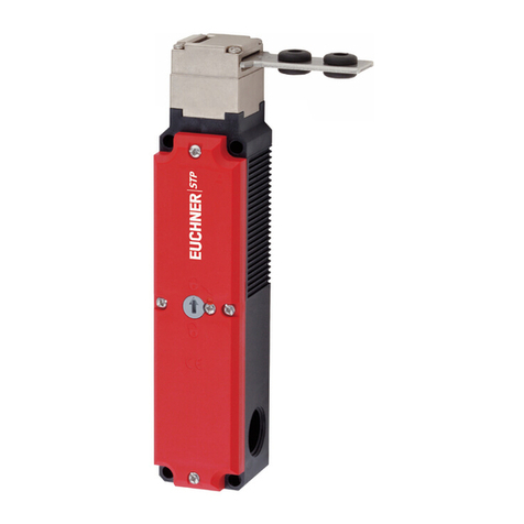
EUCHNER
EUCHNER STP3D-4141A024L024M operating instructions

Acoustic Research
Acoustic Research ARHD41 Installation and operation manual

Extron electronics
Extron electronics Matrix 12800 Series user manual
