Gigatrend Technology XP-M8VM800 User manual

M-050601
XP-M8VM800
AMD Socket 754 Processor Motherboard
User's Manual
www.DataSheet4U.com

Motherboard
XP-M8VM800
Aug. 18, 2005
Aug. 18, 2005
XP-M8VM800
Motherboard
Copyright Declaration
©2005 Gigatrend Technology Co., Ltd. All rights reserved. No part of this manual may be
reproduced, copied, translated, or transmitted in any form or by any means without express
permission from Gigatrend Technology. Companies and product names mentioned in this
document are trademarks or registered trademarks of their respective owners.
Legal Disclaimer
The information and content of this document is provided "as is", without warranty of any kind,
express or implied, including but not limited to the warranties of merchantability, fitness for a
particular purpose and non-infringement. Gigatrend Technology assumes no responsibility for
errors or omissions in this document or other documents which are referenced by or linked to
this document. The content of this document are subject to change without prior notice.
Gigatrend Technology may make improvements and/or changes in the product described in
this publication at any time and without prior notice. In no event shall Gigatrend Technology be
liable for any special, incidental, indirect or consequential damages of any kind arising out of
or in connection with the use or performance of this document. If you are uncertain about any
installation procedures, please consult a qualified computer technician.
Terms of Use
To avoid unnecessary errors of operation, please consult the user manual prior to hardware
installation. For more up-to-date information, please link to our company website at http://
www.axper.com.tw
Prior to beginning installation procedures, please make sure that your computer turned of f and
is connected to a grounded power outlet. If your system is not turned of f during installation,
this could result in harm or damage to the motherboard, the components as well as to the
user.
www.DataSheet4U.com

Contents
Motherboard Layout ...........................................................................5
1. Product Introduction ....................................................................6
1.1. Feature Summary ..........................................................................6
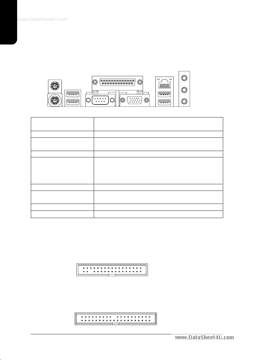
1.2. I/O Back Panel and Connectors&Jumper Setting ..........................7
1.2.1. I/O Back Panel .....................................................................................7
1.2.2. Connectors&Jumper Setting ..............................................................7
2. Hardware Installation .................................................................11
2.1. Installation of a Socket 754 CPU and Fan Sink ...........................11
2.2. Installation of Memory ..................................................................12
2.3. Installation of the Graphics Card .....
............................................13
3. BIOS Setup ..............................................................................14
3.1. Setup Screen Features (BIOS version:D2) ..................................14
3.2. Standard CMOS Features ............................................................15
3.3. Advanced BIOS Features ....
.........................................................17
3.4. Integrated Peripherals ...........................................
......................18
3.5. Power Management Setup ..........................................................20
3.6. PnP/PCI Configurations ...................
............................................22
3.7. PC Health Status ........................................................
.................23
3.8. Frequency/Voltage Control ...........................................................24
3.9. Load Fail-Safe Defaults ......................
.........................................26
3.10. Load Optimized Defaults .............................................................26
3.1 1. Set Supervisor/User Password ...................................................26
3.12. Save & Exit Setup ..............................................
...........................26
3.13. Exit Without Saving .......................................................................26
4. Driver Installation .......................................................................27
5. Installation of SATA RAID Disks .................................................29
www.DataSheet4U.com

5.1. Configuring the System BIOS for the SATA Channel ....................29
5.2. Creating RAID 0 ...........................................................................31
5.3. Creating RAID 1 ..
.........................................................................35
5.4. Deleting RAID Array ..........................
............................................39
5.5. Selecting Boot Array .......................................................
..............40
5.6. Viewing Serial Number ................................................................40
5.7. Making the SATA RAID Driver Disk ....................
............................41
5.8. Loading the VIA 8237 Serial A T A Driver .........................................41
www.DataSheet4U.com

5
English
Motherboard Layout
ATX
MS/KB
LPT
COMA
ATX_12V
Socket 754
R_USB
DDR2
DDR1
CODEC
IT8705
VIA 8237R
BIOS PCI1
PCI2
F_USB2
F_USB1
CLR_CMOS
SATA1
SYS_FAN
XP-M8VM800
F_PANEL
PCI3 BAT
F_AUDIO
CD_IN
VIA 6103L
AGP
PWR_LED
FDD
IDE2 IDE1
CPU_FAN
AUDIO
USB
LAN
VGA
SATA0
IR
SUR_CEN
SPDIF_IO
VIA K8M800
www.DataSheet4U.com

English
6
1. Product Introduction
The user manual provides steps related to quick installation. If you wish to view complete
product information, please select the " ",Open User Manual button located on the driver
CD or link to our website at http://www.axper.com to received the most up-to-date information.
1.1. Feature Summary
C P U Socket 754 for AMD AthlonTM
64 processor (K8)
1600MHz system bus
Chipset Northbridge:VIA K8M800
Southbridge:VIA 8237R
Memory 2 184-pin DDR DIMM sockets, supports up to 2GB DRAM (Max.)
Supports DDR400(Note 1) /DDR333/DDR266 DIMM
Supports only 2.5V DDR SDRAM
Slots 1 A G P slot device support
3 PCI slots support 33MHz & PCI 2.2 compliant
On-Board IDE 2 IDE controller provide IDE HDD/CD-ROM with PIO, Bus Master
(Ultra DMA33/ATA66/ATA100/ATA133) operation modes
Can connect up to 4 IDE devices
On-Board Floppy 1 Floppy port supports 2 FDD with 360K, 720K,1.2M, 1.44M and
2.88M bytes
On-Board SATA 2 SATA ports support 2 SATA devices with up to 150MB/s transfer
rate and can support data striping (RAID 0) and mirroring (RAID 1)
On-Board Peripherals 1 Parallel port supports Normal/EPP/ECP mode
1 Serial port (COMA), 1 VGA port
8 USB 2.0/1.1 ports (4 x Rear, 4 x Front by cable)
1 Front Audio connector
1 PS/2 Keyboard
1 PS/2 Mouse
On-Board VGA Built-in VIA K8M800 chip
On-Board LAN Built-in VIA6103L chip
1 RJ45 port
On-Board Sound ALC655 CODEC
Supports 2/4/6 channel
Line Out / Line In / Mic In
CD In
BIOS Licensed A W ARD BIOS
Supports BIOSNow!
I/O Control IT8705
Hardware Monitor CPU/System fan revolution detect
CPU/System temperature detect
System voltage detect
Form Factor Micro-ATX size form factor, 24.4cm x 21cm
www.DataSheet4U.com

7
English
1.2. I/O Back Panel and Connectors&Jumper Setting
1.2.2. Connectors&Jumper Setting
FDD (Floppy Disk Drive Connector)
The FDD connector is able to connect a single floppy disk drive via a FDD cable. Usually one
edge of the FDD cable is marked in red, please attach this marked edge to position 1 on the
connector.
IDE1/IDE2 (IDE Connector)
The IDE connector is able to connect two IDE devices via an IDE cable and requires checking
of the IDE jumper setting.
1.2.1. I/O Back Panel
PS/2 Mouse LAN
Parallel Port
PS/2 Keyboard
R_USB
VGACOMA
Line Out
Line In
MIC In
USB
139
240
1
342
33
(Note 1) Due to CPU limitations, if you wish to install DDR400 memory modules, install either one
double-sided or two single-sided DDR400 memory modules. The DDR400 speed will slow down
to DDR333 if two double-sided or three single-sided DDR400 memory modules are installed.
PS/2 Keyboard Connects PS/2 standard keyboard and PS/2 standard
PS/2 Mouse connector mouse
Parallel port (LPT) Connects to printer
COMA(Serial port) Connects to serial-based mouse or data processing de-
vices
VGA port Connects to 15pin D-Sub device such as a monitor
U S B Prior to use, please make sure that your system as well
(Universal Serial Bus Port) as the connected attachments support the USB interface.
If driver installation is required, please consult the USB
section of the user manual.
LAN (RJ45 LAN Port) Internet connection with speed of up to10/100Mbps
Line In Connects to optical devices, CD players and other audio
input devices
Line Out Connects to speakers or headphones
MIC In Connects to microphone
www.DataSheet4U.com

English
8
A TX_12V (+12V Power Connector)
The A TX_12V power connector provides power to the CPU. If this connector is not Attached,
the system will not start.
A TX (ATX Power Connector)
The A TX power connector provides power to the motherboard. Prior to connection, please
make sure that the power supply is disconnected.
CPU_FA N SYS_FA N
PIN SIGNAL
1 GND
2 GND
3 +12V
4 +12V
1
1
PIN SIGNAL
1 3.3V
2 3.3V
3 GND
4 VCC
5 GND
6 VCC
7 GND
8 Power Good
9 5VSB
(stand by +5V)
10 +12V
PIN SIGNAL
11 3.3V
12 -12V
13 GND
14 PS_ON
(soft on/off)
15 GND
16 GND
17 GND
18 -5V
19 VCC
20 VCC
CPU_FAN (CPU Fan Power Connector); SYS_FAN (System Fan Power Connector)
The cooler fan power connector supplies a +12V power voltage via a 3-pin power connector and possesses
a fool-proof connection design.
Most coolers are designed with color-coded power connector wires. A red power connector wire indi-
cates a positive connection and requires a +12V power voltage. The black connector wire is the
ground wire (GND).
Please remember to connect the power to the cooler to prevent system overheating and failure.
Caution!
Please remember to connect the power to the CPU fan to prevent CPU overheating and failure.
20
11
10
1
31
42
F_PANEL (Front Panel Control Connector)
The F_Panel Control Connector connects to certain connectors on the front panel of the
system casing such as IDE Hard Disk Active LED, speaker, reset, and power on/of f connectors.
Y ou can use the schematic diagram below as the basis for connection.
PIN SIGNAL
H D IDE Hard Disk Active LED
S P K Speaker Connector
R E S Reset Switch
P W Soft Power Connector
M S G Message LED/Power/Sleep LED
NC NC
1
2
19
20
HD-
HD+
RES+
RES-
NC
SPK-
MSG-
MSG+
PW-
PW+
SPK+
PIN SIGNAL
1 GND
2 +12V
3 Sense
www.DataSheet4U.com

9
English
F_AUDIO (Front Audio Connector)
Connects to the audio connector located on the front panel of the system casing
(dependent on case design). When use of the front panel audio connector is required,
please remove the 5-6 pin, 9-10 pin jumper.
Please note that use of only the front panel audio connector or the rear panel audio connector
is permitted. PIN SIGNAL
1 MIC
2 GND
3 MIC_BIAS
4 POWER
5 Front Audio (R)
PIN SIGNAL
6 Rear Audio (R)
7 Reserved
8 NO PIN
9 Front Audio (L)
10 Rear Audio (L)
S ATA0/SATA1 (Serial A T A Connector)
The SATA0/1 connector is able to connect a single Serial A TA device via a SATA cable.
For the connected SATA hard disk to work correctly , please check the related BIOS setting
and install proper driver for the SA T A controller .
PIN SIGNAL
5 RXN
6RXP
7 GND
PIN SIGNAL
1 GND
2 TXP
3 TXN
4 GND
CD_IN (Optical Drive Audio Connector)
Connects CD-ROM or DVD-ROM audio connector.
PIN SIGNAL
1 CD_L
2 GND
3 GND
4 CD_R
10
2
1
9
7
1
F_USB1 / F_USB2 (Front USB Connector)
Connects to the USB connector located on the front panel of the system casing (dependent on
case design). Note: Please make sure that each USB connection matches its designated
position. If connections are made incorrectly, the result can lead to inability to use the function
or even damage. PIN SIGNAL
6 USB Dy+
7 GND
8 GND
9 NO PIN
10 N C
PIN SIGNAL
1 POWER
2 POWER
3 USB Dx-
4 USB Dy-
5 USB Dx+
210
19
1
CLR_CMOS (Clear CMOS)
Y ou can clear the motherboard CMOS with the jumper to return your system to its initial
status. To prevent improper usage, the jumper does not include the jumper plug. If you wish
to use the Clear CMOS function, please short circuit the 1-2 Pin.
Short : Clear CMOS
Open : Normal
11
www.DataSheet4U.com

English
10
SUR_CEN (Surround Center Connector)
Please contact the place of purchase for the optional SUR_CEN cable.
65
12
PIN SIGNAL
1 SUR OUTL
2 SUR OUTR
3 GND
4 No Pin
5 CENTER_OUT
6 BASS_OUT
PWR_LED
Connects to the system power LED indicator whereby the power is indicated as ON or OFF.
However, the indicator will flash when the system is suspended.
PIN SIGNAL
1 MPD+
2 MPD-
3 MPD-
1
1
6
2
5
PIN SIGNAL
1 Power
2 No PIN
3 SPDIF
4 SPDIFI
5 GND
6 GND
SPDIF_IO
Be careful with the polarity of the SPDIF_IO connector. Check the pin assignment carefully
while you connect the SPDIF cable. Incorrect connection between the cable and connector
will make the device unable to work or even damage it. For optional SPDIF cable, please
contact your local dealer.
IR
Be careful with the polarity of the IR connector while you connect the IR. Please contact your
nearest dealer for optional IR device.
PIN SIGNAL
1 Power
2 No PIN
3 IR RX
4 GND
5 IR TX
1
B AT(Battery) The improper removal of the battery can result in harm. When replacing a
battery, please make sure you use one that is of similar brand and model
number.
For information related to battery specifications and precautions, please refer
to the manufacturer instructions.
If you wish to delete the data stored in the CMOS, please follow the steps
below:
1. Please turn of f your computer and unplug the power.
2. Remove the battery from the motherboard.
3. Wait 10 minutes and then replace the battery onto the motherboard.
4. Plug in the power supply and turn on your system.
www.DataSheet4U.com

11
English
2. Hardware Installation
1. Please make sure that the CPU used is supported by your motherboard.
2. Please be aware of the placement position of the CPU. If the CPU does not
insert properly, do not apply force but check the placement position.
3. Please make sure that an even layer of heat sink paste is added between the
CPU and the fan sink.
4. Please do not turn on the power prior to installing the fan sink. Doing so can
result in overheating and lead to permanent damage to the CPU.
5. Please follow the CPU specifications when setting the frequency. It is not
recommended that system speed settings exceed that of hardware
specifications. If you wish to set your system speed to exceed the recom
mended specifications, please check your hardware specifications eg: CPU,
graphics card, memory, hard drive
2.1. Installation of a Socket 754 CPU and Fan Sink
2. When the CPU is inserted into its position, gently press
the metal lever downwards until a click is heard. Then
add an even layer of heat sink paste between the CPU
and fan sink for heat dissipation.
1. Note the small gold colored triangle on one corner of the
CPU. Place the triangle in the corner of the CPU socket
that also have a triangle marking and gently insert the
CPU into its position.
3. Hook the clip on one side (the side without the cam
lever) of the fan sink to the mounting lug on the retention
frame.
www.DataSheet4U.com

English
12
5. Connect the 3-pin cooler power connector to the CPU
fan connector located on the motherboard.
4. Please do the same for the clip on the other side and
then gently turn the cam lever to the installed position.
(Please consult the fan sink manual for more installation
information)
2.2. Installation of Memory
1. Before installing or removing memory, please make sure that the computer
power is turned off to prevent hardware damage.
2. Please make sure that the memory used is supported by the motherboard.
3. Memory modules have a foolproof insertion design. The memory can be in
stalled only when facing the correct position. If you cannot insert the module,
please switch directions.
4. It is recommended that memory of similar capacity, specifications and brand be
used.
The motherboard supports DIMM memory modules, whereby BIOS will automatically detect
memory capacity and specifications. Memory modules are designed so that they can be
inserted only in one direction.
1. Unfasten the clips on each end of the memory
slots. Correctly align the memory module in the slot
and push downwards..
2. Once the memory module is correctly inserted, the
clips will automatically refasten. If the memory
module is positioned in the wrong direction, it will
not insert. If this occurs, please switch directions.
www.DataSheet4U.com

13
English
2.3. Installation of the Graphics Card
1. Before installing the graphics card, please carefully read the accompanying user manual.
As well, make sure the computer power is turned of f.
2. When installing or removing the graphics card, first pull out the white A G P knob before
insertion or removal. Releasing the A G P knob will hold the graphics card firmly in place.
www.DataSheet4U.com

English
14
3. BIOS Setup
BIOS (Basic Input and Output System) stores all the information of the motherboard settings
that is needed for system initiation within the CMOS. The CMOS SETUP utility allows the user
to make changes in BIOS configurations that are required or to activate certain features.
The CMOS SETUP saves each item configuration in the CMOS SRAM of the motherboard.
When the power is turned off, the battery on the motherboard supplies the required power to
the CMOS SRAM.
When the power is turned on, pushing the <Del> button during the BIOS POST (Power-On
Self Test) will bring up the CMOS SETUP screen. If you wish to enter the BIOS setup, please
press "Ctrl + F1" at the BIOS setup screen.
When using BIOS setup for the first time, it is recommended that you save the present BIOS
onto a disk in case you need to reset the BIOS back to its original settings. If you wish to
update to a new BIOS, the "BIOSNow!" can be used.
The user can select "BIOSNow!" as a way to quickly and easily update or back up BIOS
without entering the operating system.
Instructions
< , , , ,Enter> Movement in all four directions to highlight a desired option,
pressing <Enter> will select the option and take you to its
appropriate screen
<Page Up,Page Down> Used to toggle up and down the available options for a
particular item, whereby <Page Up> can also be used to
increase value option and <Page Down> to decrease
value option
<Esc> Return to main setup screen or exit setup
<F1> Gives the list of options available for each item
<F2> Gives the list of options available for the current item
<F5> Returns settings to previous values (not applicable to main setup
screen)
3.1. Setup Screen Features (BIOS version:D2)
ÚWhen you enter the CMOS SETUP screen, you will see the following screen and setting
selections as shown below.
CMOS Setup Utility-Copyright (C) 1984-2005 Award Software
Standard CMOS Features
Advanced BIOS Features
Integrated Peripherals
Power Management Setup
PnP/PCI Configurations
PC Health Status
Frequency/Voltage Control
Load Fail-Safe Defaults
Load Optimized Defaults
Set Supervisor Password
Set User Password
Save & Exit Setup
Exit Without Saving
ESC: Quit : Select Item
F8: BIOSNow! F10: Save & Exit Setup
Time, Date, Hard Disk Type...
www.DataSheet4U.com

15
English
<F6> Gives the list of options available for each item
<F7> Return to Optimized default values (not applicable to main
setup screen)
<F8> Enters BIOSNow! feature
<F9> Displays system information
<F10> Saves settings and exits setup
3.2. Standard CMOS Features
ÚIncludes the settings for items such as date, time, floppy disk drive specifications, and
hard drives connected to the IDE interface.
Date (mm:dd:yy)
Allows you to setup the date in the mm:dd:yy fashion.
Time (hh:mm:ss)
Allows you to set up the date in the hh:mm:ss fashion. The time must be entered in the
24-hour format.
IDE Channel 0/1 Master(Slave) [IDE Device Setup]
IDE HDD Auto-Detection Press "Enter" to select this option for automatic device
detection.
IDE Channel 0/1 Master(Slave) Y ou can use one of three methods:
Auto Allows BIOS to automatically detect IDE devices during POST(default)
None Select this if no IDE devices are used and the system will skip the
automatic detection step and allow for faster system start up.
Manual User can manually input the correct settings
Access Mode Use this to set the access mode for the hard drive. The four
options are:CHS/LBA/Large/Auto(default:Auto)
IDE Channel 2/3 Master
[IDE Device Setup]
IDE HDD Auto-Detection Press "Enter" to select this option for automatic device
detection.
CMOS Setup Utility-Copyright (C) 1984-2005 Award Software
Standard CMOS Features
Date (mm:dd:yy) Fri, Jan 9 2005
Time (hh:mm:ss) 22:31:24
IDE Channel 0 Master [None]
IDE Channel 0 Slave [None]
IDE Channel 1 Master [None]
IDE Channel 1 Slave [None]
IDE Channel 2 Master [None]
IDE Channel 3 Master [None]
Drive A [1.44M, 3.5"]
Drive B [None]
Floppy 3 Mode Support [Disabled]
Halt On [All, But Keyboard]
Base Memory 640K
Extended Memory 127M
Total Memory 128M
: Move Enter: Select +/-/PU/PD: Value F10: Save ESC: Exit F1: General Help
F5: Previous Values F6: Fail-Safe Defaults F7: Optimized Defaults
Item Help
Menu Level
Change the day, month,
year
<Week>
Sun. to Sat.
<Month>
Jan. to Dec.
<Day>
1 to 31 (or maximum
allowed in the month)
<Year>
1999 to 2098
www.DataSheet4U.com

English
16
Drive A / B
Allows user to configure the type of floppy drive his/she installs.
Options: None (No floppy drive installed)
360K, 5.25" (5.25 inch PC-type high-density drive; 360K bytes
capacity.)
1.2M, 5.25" (5.25 inch A T -type high-density drive; 1.2M bytes
capacity.)
720K, 3.5" (3.5 inch double-sided drive; 720K bytes capacity.)
1.44M, 3.5" (3.5 inch double-sided drive; 1.44M bytes capacity.)
2.88M, 3.5" (3.5 inch double-sided drive; 2.88M bytes capacity.)
Floppy 3 Mode Support
Allows user to configure a Japanese standard 3 Mode floppy drive.
Options: Disabled (No 3 Mode drive installed)
Drive A (3 Mode Drive installed in A:)
Drive B (3 Mode Drive installed in B:)
Both (3 Mode Drive installed in A: and B:)
Halt on
Tells the BIOS specifically which types of errors will halt the computer during the power-
on self test (POST) section of the boot.
Options: No Errors (Never halt when an error is detected)
All Errors (Halt whenever an error is detected)
All, But Keyboard (Halt whenever an error is detected with the
exception of the keyboard)
All, But Diskette (Halt whenever an error is detected with the ex
ception of the diskette)
All, But Disk/Key (Halt whenever an error is detected with the
exception of the diskette and keyboard) (default:All, But Keyboard)
Memory
When BIOS is displayed during POST, memory capacity is also displayed as shown
below:
Base Memory, Extended Memory,Total Memory (the user can verify the accuracy of
these values)
Extended IDE Drive You can use one of two methods:
Auto Allows BIOS to automatically detect IDE devices during POST(default)
None Select this if no IDE devices are used and the system will skip the
automatic detection step and allow for faster system start up.
Access Mode Use this to set the access mode for the hard drive. The two
options are:Large/Auto(default:Auto)
Hard drive information should be labeled on the outside drive casing. Enter the
appropriate option based on this information.
www.DataSheet4U.com

17
English
3.3. Advanced BIOS Features
ÚAllows the configuration of advanced settings such as boot sequence, password
check, etc.
Hard Disk Boot Priority
The user can select the boot order for hard disks connected to onboard IDE, SATA,
SCSI, RAID controllers or other add-on cards.
First / Second / Third Boot Device
The user can select the order in which the system will boot.
Options: Floppy, LS120,Hard Disk, CDROM, ZIP,USB-FDD, USB-ZIP, USB-
CDROM, USB-HDD, Legacy LAN, Disabled
Password Check
Allows user to set a password. To remove the password entry requirement, enter
SETUP and make sure there is no entry and then press <Enter>.
Options: System (Password entry is required during system start up and to enter
CMOS SETUP)
Setup (Password entry is required to enter CMOS SETUP)(default:Setup)
CMOS Setup Utility-Copyright (C) 1984-2005 Award Software
Advanced BIOS Features
Hard Disk Boot Priority [Press Enter]
First Boot Device [Floppy]
Second Boot Device [Hard Disk]
Third Boot Device [CDROM]
Password Check [Setup]
: Move Enter: Select +/-/PU/PD: Value F10: Save ESC: Exit F1: General Help
F5: Previous Values F6: Fail-Safe Defaults F7: Optimized Defaults
Item Help
Menu Level
Select Hard Disk Boot
Device Priority
www.DataSheet4U.com

English
18
3.4. Integrated Peripherals
ÚThis menu allows you to control the various ports of the computer such as IDE,
S ATA, USB, IEEE1394, COM port, LPT port, AC97 audio, etc.
CMOS Setup Utility-Copyright (C) 1984-2005 Award Software
Integrated Peripherals
: Move Enter: Select +/-/PU/PD: Value F10: Save ESC: Exit F1: General Help
F5: Previous Values F6: Fail-Safe Defaults F7: Optimized Defaults
Item Help
Menu Level
IDE DMA transfer access [Enabled]
On-Chip IDE Channel 0 [Enabled]
On-Chip IDE Channel 1 [Enabled]
OnChip Serial ATA [Enabled]
SATA Mode [RAID]
AC97 Audio [Auto]
VIA Onboard LAN [Enabled]
USB 1.1 Controller [Enabled]
USB 2.0 Controller [Enabled]
USB Keyboard Support [Disabled]
USB Mouse Support [Disabled]
On-Chip LAN Boot ROM [Disabled]
Onboard FDC Controller [Enabled]
Onboard Serial Port 1 [3F8/IRQ4]
Onboard Serial Port 2 [2F8/IRQ3]
UART Mode Select [Normal]
x UR2 Duplex Mode Half
Onboard Parallel Port [378/IRQ7]
Parallel Port Mode [SPP]
CMOS Setup Utility-Copyright (C) 1984-2005 Award Software
Integrated Peripherals
: Move Enter: Select +/-/PU/PD: Value F10: Save ESC: Exit F1: General Help
F5: Previous Values F6: Fail-Safe Defaults F7: Optimized Defaults
Item Help
Menu Level
Midi Port Address [Disabled]
x Midi Port IRQ 10
IDE DMA transfer access
Allows the user to enable or disable IDE DMA transfer access (default:Enabled)
OnChip IDE Channel 0
Allows the user to enable or disable the first onboard IDE channel (default:Enabled)
OnChip IDE Channel 1
Allows the user to enable or disable the second onboard IDE channel (default:Enabled)
www.DataSheet4U.com

19
English
OnChip Serial A TA
Allows the user to enable or disable the onboard SATA channel (default:Enabled)
S ATA Mode
Allows the user to set the SATA mode for the onboard SATA channel
Options: RAID, IDE (default:RAID)
AC97 Audio
Allows the user to use the onboard AC97 audio (default:Auto)
VIA onboard LAN
Allows the user to enable or disable the onboard LAN (default:Enabled)
USB 1.1 Controller
Allows the user to enable or disable the onboard USB 1.1 (default:Enabled)
USB 2.0 Controller
Allows the user to enable or disable the onboard USB2.0 (default:Enabled)
USB Keyboard Support
Allows user to use a USB-based keyboard (Enable if you are using a USB keyboard,
otherwise Disable) (default:Disabled)
USB Mouse Support
Allows user to use a USB-based mouse (Enable if you are using a USB mouse,
otherwise Disable) (default:Disabled)
OnBoard LAN Boot ROM
Allows user to enable or disable booting from a network drive (default:Disabled)
OnBoard FDC Controller
Allows user to enable or disable onboard FDC Controller (default:Enabled)
Onboard Serial Port 1
Allows the user to enable or disable the first onboard serial port
Options: Auto, 3F8/IRQ4, 2F8/IRQ3, 3E8/IRQ4, 2E8/IRQ3, Disabled (default:3F8/IRQ4)
Onboard Serial Port 2
Allows the user to enable or disable the Second onboard serial port
Options: Auto, 3F8/IRQ4, 2F8/IRQ3, 3E8/IRQ4, 2E8/IRQ3, Disabled (default:2F8/IRQ3)
UART Mode Select
Allows the user to determine which Infra Red(IR) function of Onboard I/O chip.
Options: Normal, IrDA, ASKIR (default:Normal)
UR2 Duplex Mode
This function is available only when UART Mode Select is not set to Normal.
Options: Half, Full (default:Half)
Onboard Parallel Port
Allows the user to enable or disable the onboard parallel port.
Options: 378/IRQ7, 278/IRQ5, 3BC/IRQ7, Disabled (default:378/IRQ7)
www.DataSheet4U.com

English
20
Parallel Port Mode
Use this to select the operation mode for the parallel port.
Options: SPP (normal) (default:SPP)
EPP (Enhanced Parallel Port)
ECP (Extended Capabilities Port)
ECP+EPP (both ECP and EPP)
Midi Port Address
Allows the user to select the Midi Port Address
Options: 300, 330, Disabled (default:Disabled)
Midi Port IRQ
Allows the user to select the Midi Port IRQ
Options: 5, 10 (default:10)
3.5. Power Management Setup
ÚThis is used to control the various power saving features of the PC.
CMOS Setup Utility-Copyright (C) 1984-2005 Award Software
Power Management Setup
: Move Enter: Select +/-/PU/PD: Value F10: Save ESC: Exit F1: General Help
F5: Previous Values F6: Fail-Safe Defaults F7: Optimized Defaults
Item Help
Menu Level
[S1]
Set suspend type to
Power On Suspend under
ACPI OS
[S3]
Set suspend type to
Suspend to RAM under
ACPI OS
ACPI Suspend Type [S1(POS)]
x USB Device Wake-Up From S3 Disabled
Soft-Off by PWRBTN [Instant-Off]
AC Back Function [Soft-Off]
Keyboard Power On [Disabled]
Mouse Power On [Disabled]
PME Event Wake Up [Enabled]
Modem Ring Resume [Enabled]
Resume by Alarm [Disabled]
x Date (of Month) Alarm Everyday
x Time (hh:mm:ss) Alarm 0 : 0 : 0
ACPI Suspend Type
Allows user to select the Advanced Configuration and Power Interface(ACPI) as S1/
POS (Power On Suspend) or S3/STR(Suspend To RAM) (default:S1/POS)
USB Device Wakeup From S3
Allows user to use a USB device to wakeup system from S3.(default:Disabled)
Soft-off by PWRBTN
Controls whether the PC shuts off immediately after hitting the power button or delaying
a few seconds. (default:Instant-off)
Options: Instant-off (PC shuts off immediately)
Delay 4 Sec. (PC shuts off after a 4sec. delay)
www.DataSheet4U.com
Table of contents
Other Gigatrend Technology Motherboard manuals