English
9
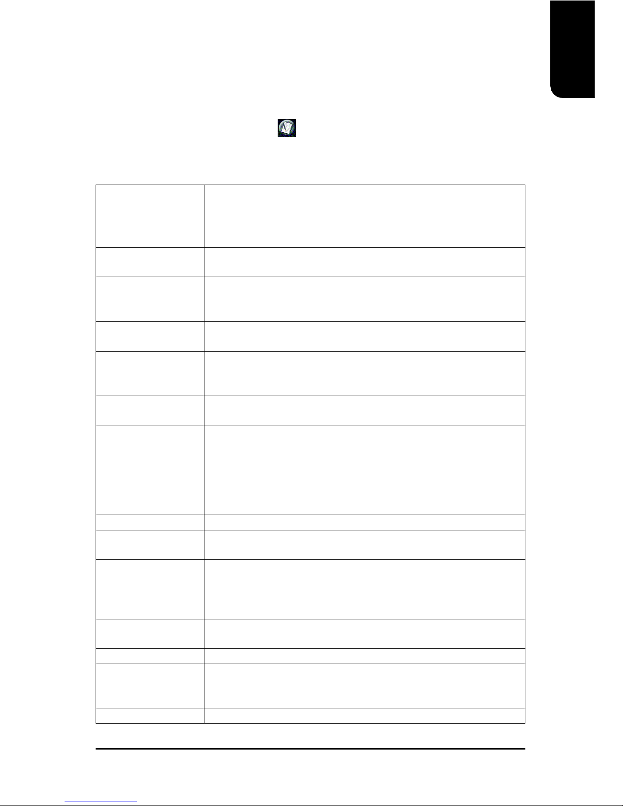
The improper removal of the battery can result in harm. When replacing a
battery, please make sure you use one that is of similar brand and model
number.
For information related to battery specifications and precautions, please refer
to the manufacturer instructions.
If you wish to delete the data stored in the CMOS, please follow the steps
below:
1. Please turn off your computer and unplug the power.
2. Remove the battery from the motherboard.
3. Wait 10 minutes and then replace the battery onto the motherboard.
4. Plug in the power supply and turn on your system.
BATTERY
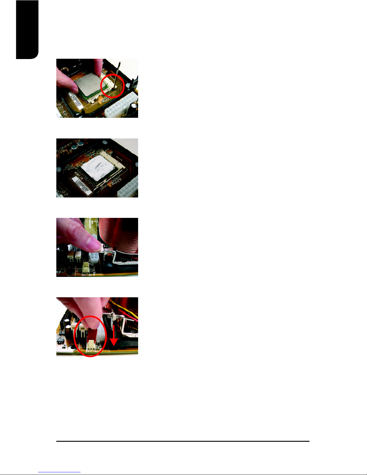
1. Please make sure that the CPU used is supported by your motherboard.
2. Please be aware of the placement position of the CPU. If the CPU does not
insert properly, do not apply force but check the placement position.
3. Please make sure that an even layer of heat sink paste is added between the
CPU and the fan sink.
4. Please do not turn on the power prior to installing the fan sink. Doing so can
result in overheating and lead to permanent damage to the CPU.
5. Please follow the CPU specifications when setting the frequency. It is not
recommended that system speed settings exceed that of hardware
specifications. If you wish to set your system speed to exceed the
recommended specifications, please check your hardware specifications eg:
CPU, graphics card, memory, hard drive
The following must be supported to allow the use of Hyper-Threading Technology:
- an Intel Pentium 4 CPU with HT
- a motherboard supporting HT
- HT selection feature within BIOS
- an operating system supporting HT
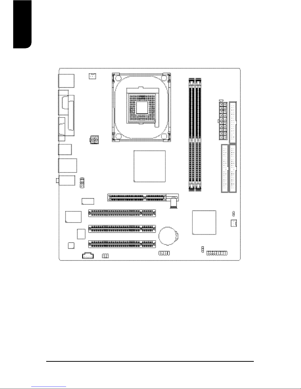
2. Hardware Installation
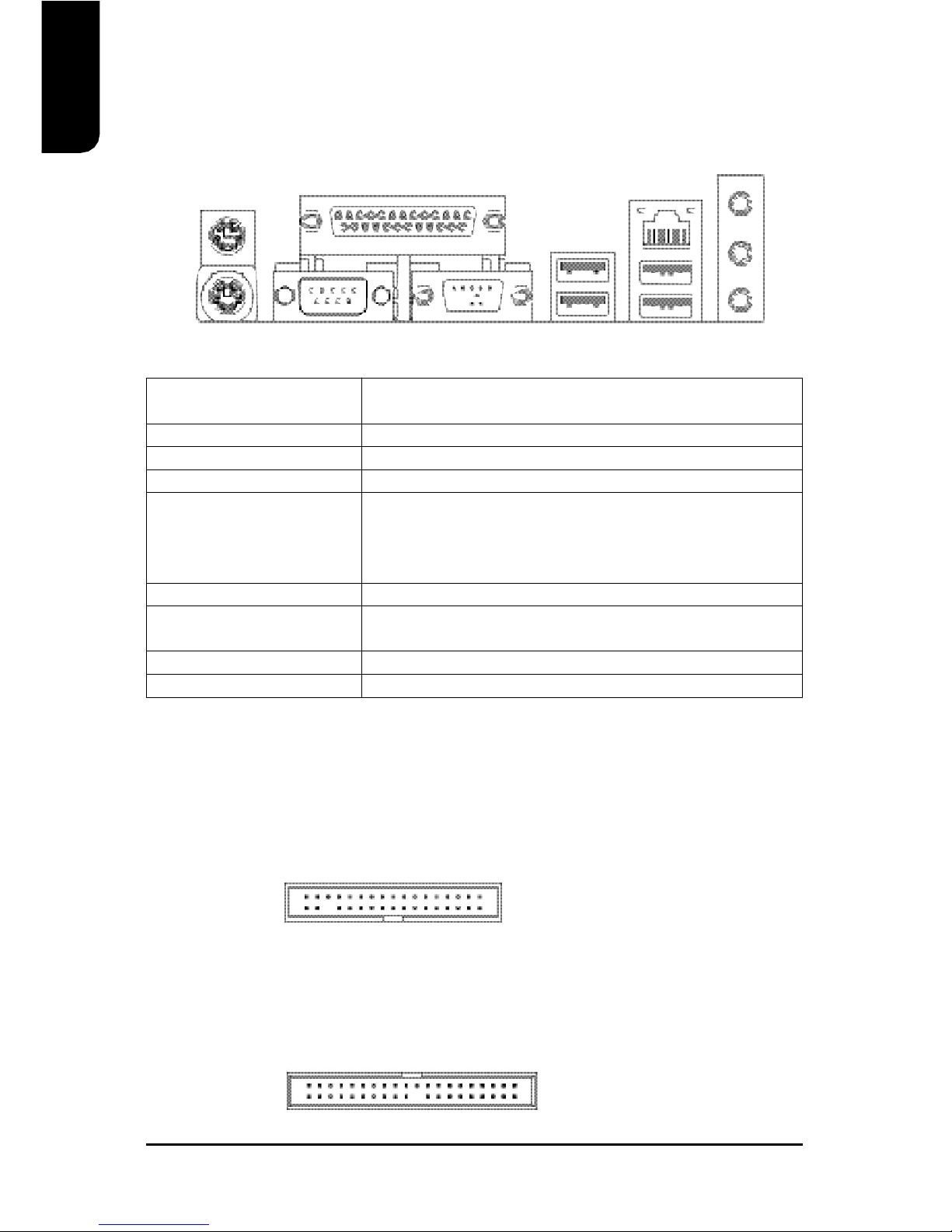
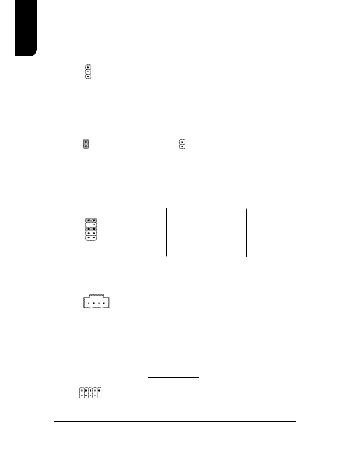
SUR_CEN (Surround Center Connector)
Connects to the optional surround center cable.
PIN SIGNAL
1SUR OUTL
2SUR OUTR
3GND
4No Pin
5CENTER_OUT
6LEF_OUT
2 6
15