Giorik Steambox Evolution SEHE Series Owner's manual

10/2016
ENGLISH: Installation, Operation and Maintenace Manual
SEHE.... - SETE.... - SEHG.... - SETG....
Steambox Evolution
MOD. HT


3
Indice
1. INSTALLATION 5
1.1 General and safety warnings �����������������������������������������������5
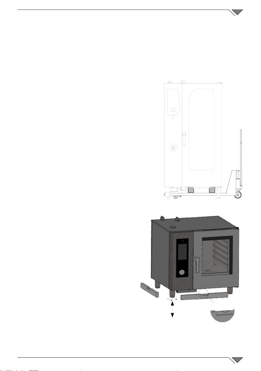
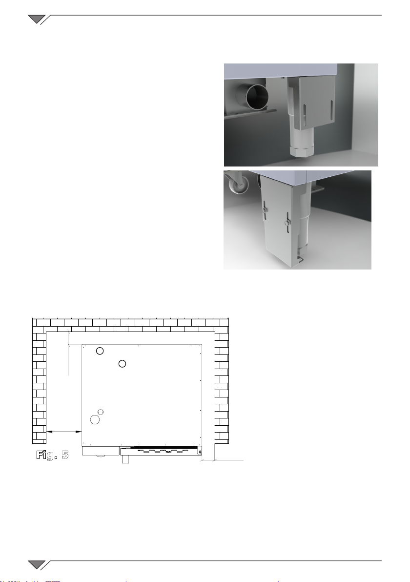
1.2 Positioning ��������������������������������������������������������������������������9
1.3 Water connection ��������������������������������������������������������������11
1.4 Connection to the drain �����������������������������������������������������11
1.5 Connection to detergent and rinse ������������������������������������12
1.6 Electric connection ������������������������������������������������������������12
1.7 Connecting the gas (gas ovens only) ��������������������������������14
1.8 Smoke exhaust ������������������������������������������������������������������15
1.9 Gas oven operating values (for gas versions only)��������������16
1.10 Adjusting the hinges and the closing pin on the door �������������17
1.11 Oven commissioning and testing ������������������������������������18
2. COOKING 20
2.1 Pictograms key �����������������������������������������������������������������20
2.2 Home Screen ��������������������������������������������������������������������22
2.3 How to interact with the touch-screen ������������������������������22
2.4 Manual cooking mode �������������������������������������������������������23
2.4a Cooking modes: convection, mixed and steam �����������������24
2.4b HOLD Mode ����������������������������������������������������������������������26
2.4c Smoking mode ����������������������������������������������������������������26
2.4d Messagge mode ���������������������������������������������������������������27
2.4d Starting and stopping cooking �����������������������������������������28
2.5 Customised cooking programs �������������������������������������������28
2.6 Creating a cooking program�����������������������������������������������29
2.7 Saving a cooking program������������������������������������������������ 30
2.8 Modifying a cooking program���������������������������������������������32
2.9 Copy, move, rename and delete �����������������������������������������32
2.10 Selecting a program from the menu���������������������������������33
2.11 The RecipeTuner interfaces����������������������������������������������34
2.12 Rack Control service mode�����������������������������������������������35
2.12a Using the Rack Control function �������������������������������������36
2.12b Creating a new RackControl program�����������������������������39
2.13 Using the EasyService function in RackControl����������������40
2.14 The scheduled departure��������������������������������������������������������������������� 41
2.15 The Regeneration function ������������������������������������������������������������41
2.15a Regeneration Programs �������������������������������������������������42
2.16 The core probe and cooking in ΔT �����������������������������������43
2.17 Recommendations for cooking: roasting, grilling and frying ������������������44
2.17a Cooking advice: cooking uniformity ������������������������������44

4
Dear Customer,
Thank you for purchasing one of our products�
This oven is part of a series of electrical equipment designed for the food sector� Our ovens
are easy to use, ergonomic and enable cooking control, while boasting a pleasant and
modern design�
The oven has a 12 month warranty that covers any manufacturing defects from the date
indicated on the Bill of Sale� The warranty covers normal operation of the oven and does
not include consumables (lamps, seals etc��) and damages caused by incorrect installation,
wear, maintenance, repair, incorrect cleaning and descaling, tampering and improper use�
2.17b Cooking recommendations: vacuum cooking and pasteurisation ��45
2.17c Cooking recommendations: hydration of the steam�������45
3. FUNCTIONS MENU 46
3.1 WASHING �������������������������������������������������������������������������46
3.2 COOLING ��������������������������������������������������������������������������48
3.3 SERVICE ���������������������������������������������������������������������������48
3.3.1 CONFIGURATION ������������������������������������������������������������49
3.3.1a Date and Time���������������������������������������������������������������49
3.3.1b Info System ������������������������������������������������������������������49
3.3.1c Language ����������������������������������������������������������������������49
3.3.1d Shower Block/Unblock��������������������������������������������������49
3.3.1e Lighting ������������������������������������������������������������������������50
3.3.2 BOILER CLEANING ����������������������������������������������������������50
3.3.3 LOG DISPLAY������������������������������������������������������������������50
3.3.4 ADVANCED SERVICES �����������������������������������������������������51
3.3.5 DATE IMPORT / EXPORT �������������������������������������������������51
4. MAINTENANCE and CLEANING 51
4.1 HUMIDITY DISCHARGE ������������������������������������������������������52
4.2 CLEANING THE GLASS��������������������������������������������������������52
4.3 CLEANING THE CONTROL PANEL VENTILATION FILTER����������52
5. CHECKS THAT CAN ONLY BE PERFORMED BY AN AUTHORIZED
TECHNICIAN 53
5.1 RESET THE SAFETY THERMOSTAT ������������������������������������������� 53
5.2 MOTOR CIRCUIT BREAKER PROTECTION����������������������������53
5.3 PROTECTION FUSES����������������������������������������������������������53
5.4 FLAME CONTROL����������������������������������������������������������������53
5.5 SPARE PARTS MANAGEMENT����������������������������������������������54
6. ALARMS DESCRIPTION 54
7. DISPOSAL OF THE APPLIANCE 56

5
1. INSTALLATION
1.1 General and safety warnings
• Read this manual thoroughly
before installation and use
of the oven, since it gives
important instructions
regardingitssafeinstallation,
use and maintenance�
• Keep the manual in a
location that can be easily
accessed by the operators
for further consultation�
• Always include the manual
if the oven is transferred; if
necessary, request a new
copy from the authorized
dealer or directly from the
manufacturer�
• As soon as the packaging
is removed, make sure
the appliance is in good
condition and there was
no damage caused during
transport� Never install or
use a damaged appliance;
if in doubt, contact the
after-sales technical
assistance or your local
dealer immediately�
• Since the packaging
material is potentially
dangerous, it must be kept
out of the reach of children
or animals and disposed
of correctly in compliance
with local regulations�
• Before installing the
equipment, check that the
plants are compliant with
the regulations in force
in the country of use and
with that stated on the
information plate�
• Installation or maintenance
different to those indicated
in the manual can cause
damage, injury or fatal
accidents�
• Installation, extraordinary
maintenance and repair
operationsontheequipment
must only be performed
by professionally qualied
personnel and following the
manufacturer'sinstructions�
• During assembly of the
equipment, the transit or
permanence of staff not
assigned to installation is
not allowed in the work
area�
• The appliance has been
designedtocookfoodstuffs

6
in closed environments
and must be used only for
this function� Any different
use must therefore be
avoided as it is considered
improper and dangerous�
• The appliance must only
be used by personnel who
have been appropriately
trained in its use� To avoid
the risk of accidents or
damage to the equipment,
it is essential that the staff
is constantly trained with
regard to safe operation�
• The appliance must not
be used by persons with
reduced physical, sensory
or mental capacities or by
those who do not have
the necessary experience
or knowledge unless
they are supervised or
instructed in the use
of the equipment by a
person who is responsible
for their safety�
• The appliance must
be placed in a suitably
ventilated room to
prevent the excessive
accumulation of harmful
substances in the air�
• Children must be supervised
to ensure they neither play
with or use the appliance�
• During operation, pay
attention to the hot areas
on the exterior surfaces
of the equipment which,
during operation, can
exceed 60°C�
• The use of hearing
protection is not necessary
since the sound pressure
level of the oven is lower
than 70 dB(A)�
• In the event of failure
or malfunctioning, the
equipment must be
deactivated; any repairs
must only be performed
by an assistance centre
authorized by the
manufacturer and original
spare parts must be used�
• Disconnect the appliance
from the electric power
supply before performing
any installation or
maintenance intervention�
• Interventions, tampering or
modicationsnotexpressly
authorised, which do not
respect that stated in this

7
manual, will make the
warranty null and void�
• Do not place other heat
sources, such as fryers
or cooking plates, near to
the oven�
• Do not deposit or use
ammable substances
near the equipment�
• In the event of prolonged
non-use, the electricity,
water and gas must be
turned off�
• Before commissioning the
appliance, make sure that
all parts of the packaging
have been removed,
making sure they are
disposed of in compliance
with current legislation�
• Any changes to appliance
installation that become
necessary must be
approved and performed
by authorized technicians�
• The appliance is intended
for professional use only�
• No changes of any kind are
permitted to the wiring of
the equipment�
• Failure to comply with the
previous warnings can
compromise both your
safety and the safety of the
equipment�
• When the cooking
chamber is hot, be careful
when opening the door�
BURNS HAZARD!!
• The trays and grills must
be extracted from the hot
oven using heat-resistant
protective gloves for the
hands�
• Use protective glasses
and suitable gloves during
cooking chamber cleaning
operations�
• ATTENTION: the oor
near to the oven could be
slippery�
• The information plate
provides important technical
information: these are
essential if interventions
must be requested for
maintenance or repairs of
the appliance; therefore,
it must not be removed,
damagedormodied.
• The version of the gas

8
ovens conform to the Gas
Directive 2009/142/EEC
and have therefore been
issuedwithaCEcerticate
byanotiedbody.
• The equipment complies
with the essential
requirements of the
Machinery Directive
2006/42/EC�
• The equipment complies
with the essential
requirements of the
Electromagnetic
Compatibility Directive
2014/30/EC�
• The equipment complies
with the essential
requirements of the
Low Voltage Directive
2014/35/EC�

9
1.2 Positioning
The appliances have been designed to be installed indoors� They cannot
be used outdoors and cannot be exposed to atmospheric agents�
The place designated for the installation of the oven must have a rigid, level
and horizontal surface, which must be able to safely support the weight of
the device/support assembly and the load at maximum capacity�
The appliance must be transported to the
place of installation packed on the wooden
pallet� The oven must be handled using a
transpallet, taking all precautions that it does
not overturn� Also at the end of its life span
the oven must be loaded onto a pallet and
handled with great care in order to prevent
the hazard of overturning� Two wooden
beams are inserted into the packaging of
the free-standing ovens in order to handle
the oven without damaging it� Position
the beams as in Fig. 1 and proceed with
handling�
The appliance must be placed in a suitably
ventilated room to prevent the excessive
accumulation of harmful substances in the air�
All of the materials used for
packaging are compatible with the
environment; they can be stored
without danger or be disposed of
according to local regulations�
The oven must be level: to adjust
the height of the levelling feet use
a spirit level, as indicated in Fig. 2�
Unevenness or inclinations of a
certain importance can compromise
the operation of the oven�
Remove the entire protective lm
from the external panels of the
appliance, detaching it slowly to
remove all traces of adhesive�
Make sure that all openings and
holes designed for heat intake/
discharge are not obstructed�
Fig. 1
-
+
-
+
Fig. 2

10
Ifitisdeemednecessary,theovenswithawheeledstructurecanbexed
totheoorusingthebracketssuppliedwiththeoven.
Remove the two screws that x the
rear foot to the frame, position the
blocking bracket as per Fig. 3 and use
the screws that have just been removed
toxittotheframe
Placethe bracketonthe ooras per
Fig. 4� Trace the position of the holes
ontheoorandblockthebracketusing
suitable xing systems. Perform the
same procedure on the rear foot on the
opposite side�
The oven should be installed exclusively
on a stable support�
Remove the packaging from the
appliance and make sure it is intact�
Arrange it in the place of use being
careful not to place it on top of or against
walls, bulkheads, partition walls, kitchen
furnitureorcoatingsinammablematerial.
Werecommendyoustrictlycomplywithre-preventionregulationsinforce.
A minimum distance of
50 mm on each side must
be maintained between
the oven and the walls
or other equipment� It is
recommended to leave 500
mm space between the left
side of the oven and the
corresponding wall of the
room (Fig. 5) to allow the
oven to be installed easily
and facilitate successive
maintenance�
It is good practice to have the periodic maintenance of the ovens performed
every year by an authorised technician and in compliance with specic
regulations� On this occasion all controls regarding the operation of electric
components (switches, electronics, solenoid valves, heating elements, motors,
cooling fans, etc�) and the mechanical controls relative to functionality of the
doors, hinges, closing mechanisms, and gaskets will be performed�
Fig. 3
Fig. 4
50
mm
500
mm
50
mm
Fig. 5

11
1.3 Water connection
The maximum water pressure must be (600 kPa) 6 bars� If the water
pressure of the mains water should be over this value, a pressure reducer
must be installed upstream from the oven�
The minimum water pressure for correct operation of the oven must be
above 1,5 bars�
The oven has two inlet for water,
one for mains water(1) and another
for softened water(2) (Fig. 6)� The
installation of a softener-lime scale
eliminator is always recommended
to bring the hardness of inlet water
to valuesbetween 8° and 10°F�
Before connection, drain off a
sufcientamountofwatertoclean
the pipe from metal residues�
Connect the "Water" pipeline to
water mains and install a shut-off
valveandalteronthepipe.
Ensure that the shut-off valve is
positioned so that it can be easily operated by the operator at any time�
Attention: if the water supply pipe malfunctions, it should be replaced
with a new one while the old broken one should not be used again�
1.4 Connection to the drain
The oven has a water drain; it is placed at the lower rear part of the appliance
and has a tube with diameter of 50 mm�
Connect the pipe that projects from
the drainage device (Fig. 7, ref. A)�
The draining system consists of a
trap; it is advisable to connect the
pipe to an open funnel�
Make sure the internal trap is full
of water; otherwise ll it up with
water through the drain present in
the cooking chamber�
Fig. 7
A
Fig.6
1 2

12
1.5 Connection to detergent and rinse
For proper startup of washing steps you need to
connect the oven to the tanks of detergent and
rinse aid� To connect you must insert the two pipes,
white one for detergent and red one for the rinse
agent in the respective canisters� The two pipes
are located at the bottom left of the oven(g.8)�
1.6 Electric connection
As prescribed, the electrical system
musthaveanefcientearthsystem,
as required by the regulations in
force� The electrical safety of the
appliance can only be ensured when
the electrical system is conform�
Before making the electrical connection,
check the mains voltage and frequency
values to ensure that they conform to
the requirements of the appliance, as
indicated on its data plate (Fig. 9)�
For direct connection to the mains,
a device, sized according to the load,
must be placed between the appliance
and the mains itself, which ensures
disconnection� Its contacts should have a
minimum opening distance that enables
complete disconnection under the
conditions of category III overvoltage,
according to installation rules; this device
should also be located so that it can be
easily used by the operator at any time�
Turn the master switch, to which the
Fig. 9
POWER SUPPLY
TOT. POWER kW
OVEN POWER kW
MOD NR
BOILER POWER kW 1,0
3N 400V AC 50 HZ
10,0
SEHE061W
000000/01/16
11,4 IP
Fig. 10
Electric Model SEHE061 SETE061 SEHE062 SETE062 SEHE101 SETE101 SEHE102 SETE102 SEHE201 SETE201 SEHE202 SETE202
Weight 107 107 170 170 140 140 190 190 260 260 340 340
Voltage 3N 400V 3N 400V 3N 400V 3N 400V 3N 400V 3N 400V 3N 400V 3N 400V 3N 400V 3N 400V 3N 400V 3N 400V
Frequency(Hz) 50 50 50 50 50 50 50 50 50 50 50 50
Absorbed
power (kW)
11.4 10.4 21.4 20.4 16.7 15.7 28.3 25.8 33.3 30.8 54.1 51.6
Minimum
power cable
section
(mm2)
5 x 2.5 5 x 2.5 5 x 10 5 x 10 5 x 4 5 x 4 5 x 10 5 x 10 5 x 10 5 x 10 5 x 16 5 x 16
Fig. 8

13
power supply plug will be connected, to position 0 (zero)� Have the socket
cable section checked by qualied staff to make sure it suits the power
absorbed by the device�
Loosen the screws that x the
left side of the oven and remove it
(Fig. 10). The exible cable must
be in polychloroprene or equivalent
oil-resistant synthetic elastomer
sub-sheath� Use a cable with section
suitable to the load corresponding to
every appliance, as indicated in the
table (tab. 1)�
Insert the power cord into the hole of the cable gland located on
the left bottom side of the oven�
Connect the cable to the terminal block following the instructions
given in tab. 2�
Secure the cable with the cable gland�
The supply voltage of the appliance is operation must not
deviate from the nominal voltage by ± 10%�
Theappliancemustbeincludedintoanequipotentialsystemwhoseefciency
is checked in compliance with the standards in force� For the connection use
the clamp, placed on the frame and marked with the symbol Fig. 11, to
which a cable with the minimum section of 10 mm² must be connected�
For gas ovens, wait until the gas connection to the appliance has also been
completed before re-mounting the side panel of the oven; instead, for electric
ovens,onnishingtheelectricconnection,re-mountthesidepanel.
Gas Model SEHG061 SETG061 SEHG062 SETG062 SEHG101 SETG101 SEHG102 SETG102 SEHG201 SETG201 SEHG202 SETG202
Weight 135 135 190 190 165 165 220 220 270 270 350 350
Voltage 1N 230V 1N 230V 1N 230V 1N 230V 1N 230V 1N 230V 1N 230V 1N 230V 1N 230V 1N 230V 1N 230V 1N 230V
Frequency (Hz) 50 50 50 50 50 50 50 50 50 50 50 50
Absorbed power
(kW)
1.4 0.4 1.4 0.4 1.7 0.7 3.3 0.8 3.3 0.8 4.1 1.6
Minimum power
cable section
(mm2)
3 x 1 3 x 0.75 3 x 1 3 x 0.75 3 x 1 3 x 0.75 3 x 1 3 x 0.75 3 x 1 3 x 0.75 3 x 2.5 3 x 1
tab. 1
Electric ovens Gas ovens
L1 L2 L3 N L N
Between phase
and
there must be
a difference in
potential of 230 V�
tab. 2
Fig.11

14
1.7 Connecting the gas
(gas ovens only)
Nota bene:
The oven is calibrated originally
for operation with the type of gas
speciedonplacingtheorder.
The type of gas for which the oven
is adjusted is given on the technical
plate positioned on the appliance
(Fig. 12, ref. A)�
During the inspection, make sure
that the factory calibrations on the
burners are appropriate for the
specic type of installation, through
the analysis of the gases produced by
combustion(CO2andCO)andthevericationoftheheatoutput.
Specically,with theovenoperatingat fullregime, thevaluesofundiluted
CO at the exhaust must remain within 1000 ppm� Should there be any
undiluted CO beyond this parameter, the burner adjustments must be checked
exclusively by a technician authorised by the manufacturer, who will make the
necessary changes to the devices which take care of the combustion and to
their parameters�
The data detected must be noted and become an integral part of the technical
documentation of said appliance�
Installation prescriptions
The oven installation and commissioning operations must be performed by
qualiedstaffonlyincompliancewithrulesandregulationsinforce.
The gas plants, the electric connections and the places of installation of the
appliances must be in compliance with the regulations and the standards in force�
Remember that the air necessary for combustion of the burners is 2 m³/h per kW
of power installed�
In businesses open to the public, accident-prevention regulations must be
compliedwithalongwithre-preventionsafetyandanti-panicregulations.
Theconnectiontothegassupplyttingcanbemadeusingexiblemetal
hoses; placing a type-approved cut-off cock in an easily accessible point�
Makesurethattheexiblemetalhose,forconnectiontothegasinlettting,
does not touch the hot parts of the oven and that it is not subjected to twisting
or extension�
Usexingstrapsthatareincompliancewiththeinstallationregulations.
Fig. 12
A

15
Checks to perform before installation
Check on the technical plate on the left-hand side of the oven that the
appliance has been tested and approved for the type of gas that the
user's premises (Fig. 12, ref. A)�
Check, using the data on the technical plate (Fig. 12), to make sure that
thepressure reducercapacityis sufcientfor theappliancesupply. Do not
install section reducers between the reducer and the appliance�
It is recommended to install a gas
lter upstream from the pressure
regulator in order to ensure optimal
operation of the oven�
Connect the oven to the gas supply
plant via a tube with diameter of 3/4” and
internal section no smaller than 20 mm
(Fig. 13)� Envision cocks or drain valves
with an internal diameter no smaller than
thettingtubementionedabove.
After connecting the pipe, make sure that
the joints and couplings have no leaks� To
dothis,usesoapywaterorspecicfoamy
product to identify the leak�
It is good practice to have the periodic
maintenance of the gas ovens performed
every year by an authorised technician;
onthisoccasiontheue gases willbeanalysedandthe heatoutputwillbe
checked�
1.8 Smoke exhaust
In compliance with the installation
regulations, the ovens must be
used in premises suitable for the
evacuation of combustion products�
The oven drain can be connected
via a forced evacuation system,
such as a hood with mechanical
extractor (Fig. 14)� In this case,
the gas supply to the appliance
must be controlled directly by this
system and must cut-off whenever
the suction ow rate drops below
Fig. 13
Fig. 14

16
the values prescribed� When the appliance is installed under the extraction
hood, check that the following indications are respected:
a) the volume extracted must be higher than that of the ue gases
generated (see current regulation);
b) the material with which the hood lter is made must resist the
temperatureoftheuegaseswhich,onexitingtheconveyor,canreach300°C;
c) the end part of the appliance evacuation pipe must be positioned
inside the base perimeter projection of the hood;
d) the gas supply must be restored manually following a block caused by
insufcientsuction.
1.9 Gas oven operating values (for gas versions only)
Model SBHG061 SBTG061 SEHG101 SETG101 SEHG102 SETG102 SEHG201 SETG201 SEHG202 SETG202
Voltage 1N 230V 1N 230V 1N 230V 1N 230V 1N 230V 1N 230V 1N 230V 1N 230V 1N 230V 1N 230V
Frequency (Hz) 50 50 50 50 50 50 50 50 50 50
Absorbed power
(kW)
1�4 0�4 1�7 0�7 3�3 0�8 3�3 0�8 4�1 1�6
Nom� heat input (kW)
12 12 19 19 27 27 36 36 54 54
Section power
cable (mm 2 )3 x 1�5 3 x 1�5 3 x 1�5 3 x 1�5 3 x 1�5 3 x 1�5 3 x 1�5 3 x 1�5 3 x 1�5 3 x 1�5
Nominal heat input
Gas consumption
SExG061 SExG101 SExG102 SExG201 SExG202
G30 kg/h 0�94 1�49 2�13 2�84 4�26
G20 m3/h 1�26 2�01 2�86 3�81 5�71
G25 m3/h 1�47 2�33 3�32 4�43 6�65

17
1.10 Adjusting the hinges and the closing pin on the door
Once the oven has been positioned correctly in the designated installation
location, the closure and seal of the gasket on the oven chamber door must
be checked�
The hinges of the door should be adjusted so as to ensure maximum
sealing of oven's door during the cooking cycles� Both the upper and lower
hinges can be adjusted�
To adjust the door seal when needed, loosen the bolt (Fig.15) and move the
door to the desired position� When the adjustment is complete, tighten the bolt�
COUNTRY CAT G30 G31 G20 G25 G27
G2�350
G25�1
IT - ES - IE
PT - GB - CH II2H3+ P mbar 28-30 37 20 // // // //
DK - FI - EE - NO
LV - CZ - SI - SE II2H3B/P P mbar 30 30 20 // // // //
FR - BE II2E+3+ P mbar 28-30 37 20 25 // // //
GR II2H3+ P mbar 28-30 37 20 // // // //
II2H3B/P 30 30 20 // // // //
CY II2H3+ P mbar 28-30 37 20 // // // //
II2H3B/P 30 30 20 // // // //
LT II2H3+ P mbar 28-30 37 20 // // // //
II2H3B/P 30 30 20 // // // //
AT II2H3B/P P mbar 50 50 20 // // // //
CH II2H3+ P mbar 28-30 37 20 // // // //
II2H3B/P 50 50 20 // // // //
MT - IS I3B/P P mbar 30 30 // // // //
DE II2ELL3B/P P mbar 50 50 20 20 // // //
NL II2L3B/P P mbar 30 30 // 25 // // //
RO
II2H3B/P
P mbar
30 30 20 // // // //
II2E3B/P 30 30 20 // // // //
II2L3B/P 30 30 // 20 // // //
SK
II2H3+
P mbar
28-30 37 20 // // // //
II2H3B/P 30 30 20 // // // //
II2H3B/P 50 50 20 // // // //
TR II2H3+ P mbar 28-30 37 20 // // // //
II2H3B/P 50 50 20 // // // //
PL II2ELwLs3B/P P mbar 37 37 20 // 20 13 //
LU I2E P mbar 20 // // // //
HU II2HS3B/P P mbar 30 30 25 // // // 25
Gas pressure

18
The closing pin on the door can be
adjusted in depth to eliminate any
steam leakage during cooking�
The pressure exerted by the door
on the gasket can be adjusted by
tightening the pin to increase it or
loosening the pin to decrease it
(Fig.16)�
When the adjustment is complete,
tighten the bolt, making sure the
closing anchor is located at the bottom�
1.11 Oven commissioning and testing
Before putting the oven into operation, you should carefully carry out all
the necessary checks to ascertain the conformity of the equipment and
installation of the appliance as provided by law and according to the technical
and safety instructions given in this manual�
The compliance of the following must also be checked:
The temperature in the oven installation area must be greater than +4° C�
The cooking chamber must be empty�
Allpackagingmustbeentirelyremoved,includingtheprotectivelmapplied
on the oven walls�
The vents and air slots must be open and free of obstructions�
Any pieces of the oven that were removed for installation must be replaced�
The general electrical switch must be closed and the water and gas cut-off
cocks upstream of the appliance must be open�
Testing
The oven should be tested by completing a cooking cycle to verify that
the equipment works properly, without any anomalies or problems�
Fig. 15
Fig. 16

19
Switch the oven on by pressing the “ON / OFF” key (Fig. 17 / Rif. 1)
Set a cooking cycle with temperature at 150 ° C, time set to 10 min� and
humidity at 5%�
Carefully check the points given in the following list:
The lights in the cooking chamber turn on when pressing the button and
turn off automatically after 45 seconds if they are not turned off early by
pressing the button again�
The oven stops if the door is opened and starts again when the door is closed�
The fan/s motor reverses the direction of rotation automatically; reversal takes
place every 3 minutes approx� (time varies depending on the cooking time)�
For the ovens with two fans in the cooking chamber, the motors have the
same direction of rotation�
Check the water escaping in the direction of the fan from the humidity inlet
tube in the cooking chamber�
At the end of the cooking cycle, the oven emits an audible signal�
Venerdì 11 marzo 2016 16:20
Manual
Steamed Grilled Roasted
Fried Braised Au Gratin
Baked Low Temp� Smoked
Eggs Rack Control Regenerated
Recipes
Rif� 1
ON / OFF
Rif� 3
FUNCTION button
Rif� 4
CHAMBER LIGHTS
Rif� 4
KNOB
Fig. 17
Rif� 2
HOME Screen
Rif� A
Rif� B
Rif� C

20
2. COOKING
2.1 Pictograms key
Start screen
Recipe screen by product type
Pasta and Rice
Meat
Poultry
Fish and seafood
MANUAL
STEAMED GRILLED
RECIPES
ROASTED
LOW TEMP�
BAKED (bread
and pastry
AU GRATINBRAISED
FRIED and
SAUTÉED
RACK CONTROL RIGENERATION
SMOKED
EGGS
FUNCIONS CHAMBER LIGHTS
This manual suits for next models
27
Table of contents
Other Giorik Oven manuals