Gira 5122 00 User manual

RF remote control
RF remote control, 2-gang
Order no.: 5122 00
RF remote control, 4-gang
Order no.: 5124 00
Operating instructions
1 Safety instructions
Electrical devices may only be mounted and connected by electrically skilled persons.
Serious injuries, fire or property damage possible. Please read and follow manual fully.
The radio communication takes place via a non-exclusively available transmission path, and is
therefore not suitable for safety-related applications, such as emergency stop and emergency
call.
These instructions are an integral part of the product, and must remain with the end customer.
2 Battery safety instructions
This device or its accessories are supplied with batteries in the form of button cells.
DANGER! Batteries can be swallowed. This can lead directly to death by suffocation. Danger-
ous substances may cause severe internal burns leading to death within 2 hours.
Keep new and used batteries away from children.
Do not use devices if the battery compartment does not close securely and keep away from
children.
If you suspect that a battery has been swallowed or is in any orifice of the body, seek immediate
medical attention.
WARNING! Improper handling of batteries can result in explosion, fire or chemical burn due to
leakage.
Do not heat or throw batteries into fire.
Do not reverse polarity, short-circuit or recharge batteries.
Do not deform or disassemble batteries.
Replace batteries only with an identical or equivalent type.
Remove empty batteries immediately and dispose of in an environmentally friendly manner.
3 Function
System information
This device is a product of the KNX system and complies with the KNX directives. Detailed tech-
nical knowledge obtained in KNX training courses is a prerequisite to proper understanding.
The range of a radio system depends on various external circumstances. The range can be op-
timised by the choice of installation location. The product documentation for this device contains
application basics for the KNX radio system.
Planning, installation and commissioning are carried out with the aid of KNX-certified software
of version ETS5 or higher. You can find the up-to-date product database, technical descriptions
and Declaration of Conformity on our Internet site.
Intended use
– Operation of loads, e.g. light on/off, dimming, Venetian blinds up/down, brightness values,
calling up and saving light scenes
– Operation in cabled KNX systems via media coupler (see chapter Accessories)
1 / 5
32590832 10867223 20.12.2019

RF remote control
Product characteristics
– The pushbutton functions switching, dimming, controlling blinds, value transmitter, calling
up moods, etc.
– Two or four button pairs for rocker or push-button function
– Two-colour LED to display actuation, sending status and actuator feedback
– Battery-powered device
To ensure good transmission quality, keep a sufficient distance from any possible sources
of interference, e.g. metallic surfaces, microwave ovens, hi-fi and TV systems, ballasts or
transformers.
Energy saving mode
The device switches to the energy saving mode after a preset time. In energy saving mode, the
LEDs remains switched off. During operation, the energy saving mode is exited.
Operations from the energy saving mode are executed immediately.
Semi-bidirectional mode
Battery-operated KNX RF devices work in semi-bidirectional mode. If this device is not the only
control panel, we recommend the use of the "Rocker function", as otherwise two button-presses
may be necessary for operation.
4 Operation
Figure1: Radio hand transmitter 2-gang and 4-gang
(1) Status LED
(2) Release the
Operating a function or load
■ Switch: Short press on button.
■ Dim: Long press on the button.
■ Move Venetian blind: Long press on button.
■ Stop or adjust Venetian blind: Short press on button.
■ Call up light scene: Short press on button.
■ Save light scene: Long press on button.
■ Set value: Press button briefly.
LED function
The two-colour LED (1) indicates actuations, sending status and actuator feedback. The colour
assignment may deviate or the function may sometimes be invisible, depending on the pro-
gramming.
2 / 5
32590832 10867223 20.12.2019
RF remote control
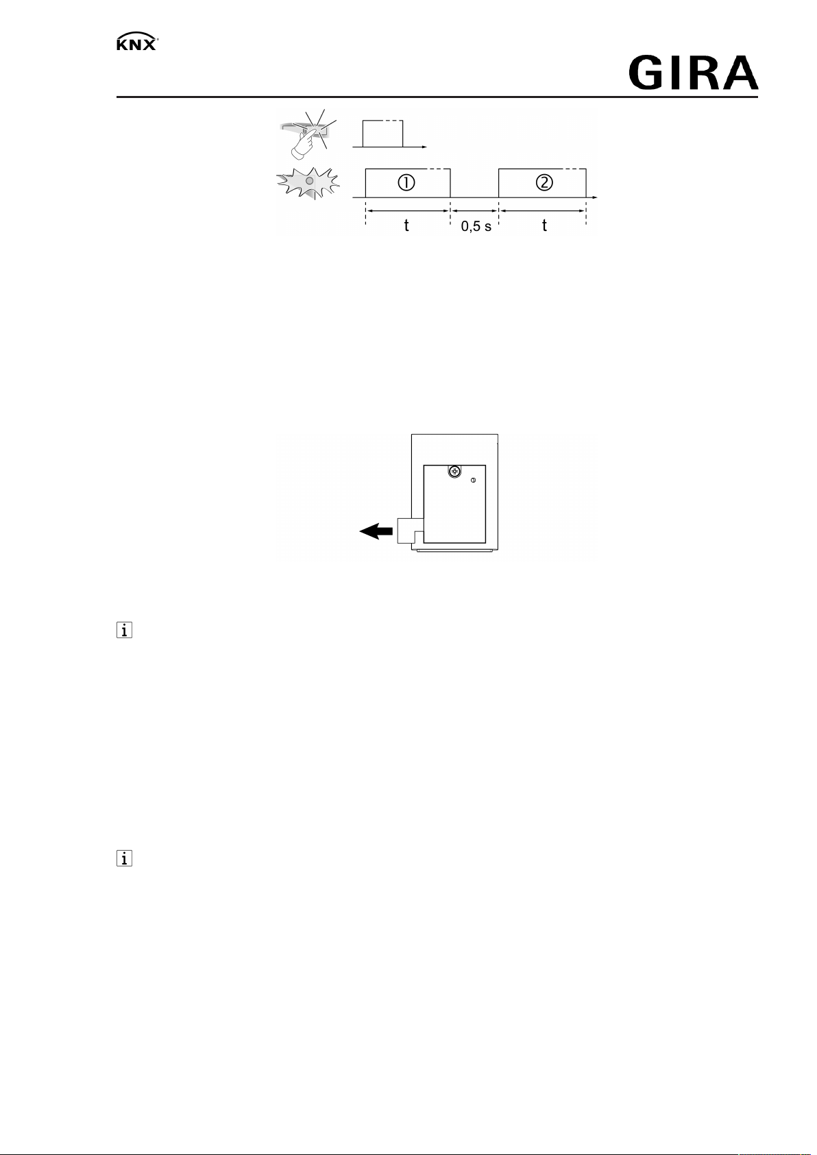
Figure2: LED function
Phase 1: Actuation/sending display (red) or low battery level (flashing)
Phase 2: Actuator feedback (red/green) or sending error (flashing)
5 Commissioning
Activating the battery
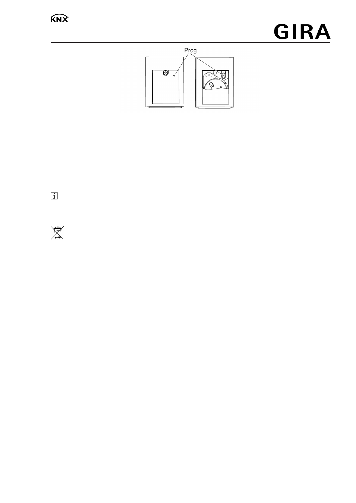
The battery is already inserted in the state as supplied. Pull the plastic strip (Figure 3) to activ-
ate.
Figure3: Activating the battery
Changing the battery
Obey the battery safety instructions.
■ Unscrew the battery compartment on the back of the hand-held transmitter. Use a small
flat head screwdriver or Phillips screwdriver PH1 for this.
■ Keep contacts of batteries and device free of grease.
■ Remove the old battery.
■ Apply battery to the positive contact of the battery holder. Observe polarity: the positive
pole of the battery must be at the top.
■ Press gently on battery to snap it in.
■ Close and screw the battery compartment with max. 0.3Nm.
Load the address and the application software
Project design and commissioning with ETS5 or more recent.
If the device does not contain any application software, or the wrong application software,
then the Status LED (1) flashes slowly in red and green for 3 seconds after a button-
press.
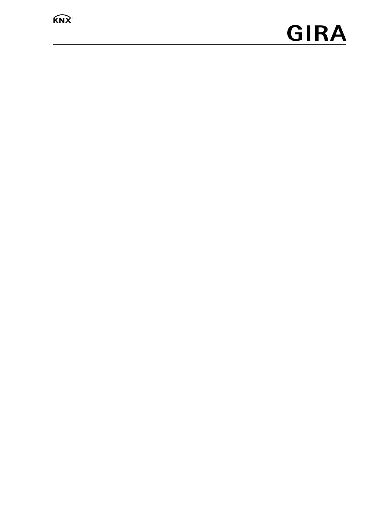
The Prog (Figure 4) button can be pressed with a thin wire or paper clip through the hole in the
battery cover.
3 / 5
32590832 10867223 20.12.2019
RF remote control
Figure4: Button Prog
■ Press the Prog button.
The status LED (1) lights up red.
■ Load the physical address and domain address into the device.
The status LED goes out.
■ Write the physical address and domain address on the inner side of the battery compart-
ment lid.
■ Load the application software into the device.
Before updating the system software or changing the application software, replace a bat-
tery with a new, unused battery.
6 Disposal of batteries
Remove empty batteries immediately and dispose of in an environmentally friendly
manner. Do not throw batteries into household waste. Consult your local authorities
about environmentally friendly disposal. According to statutory provisions, the end
consumer is obligated to return used batteries.
7 Technical data
Rated voltage DC 3 V
Battery type 1×Lithium CR 2450N
Ambient temperature -5 ... +45 °C
Degree of protection IP20
Dimensions L×W×H
Order no. 5122 00 55×40.5×15 mm
Order no. 5124 00 93×53×15.5 mm
KNX
KNX medium RF1.R
Commissioning mode S-mode
Radio frequency 868.0 ... 868.6 MHz
Transmission capacity max. 20 mW
Transmitting range in free field typ. 100 m
Receiver category 2
8 Troubleshooting
After a button has been pressed, the status LED flashes red slowly for 3 seconds.
Cause: Battery in the hand-held transmitter is almost empty.
Changing the battery (see chapter Commissioning – Changing the battery).
4 / 5
32590832 10867223 20.12.2019
RF remote control
Receiver does not react, status LED displays a transmission error. Status LED flashes red
quickly for 3 seconds.
Cause: The hand-held transmitter cannot send the telegram, e.g. due to a missing group ad-
dress.
Correct the programming.
Receiver does not react, actuator feedback is not displayed.
Cause 1: Radio range exceeded. Structural obstacles reduce the range.
Using a radio repeater.
Cause 2: Receiver or media coupler is not ready for operation.
Check the receiver and mains voltage or media coupler.
Cause 3: There are radio faults, e.g. through outside radio.
Eliminate radio interference.
9 Accessories
RF/TP media coupler or RF repeater Order no. 5110 00
KNX RF USB data interface (USB stick) Order no. 5120 00
10 Conformity
Hereby Gira Giersiepen GmbH & Co. KG declares that the radio system type
Order no. 5122 00 , 5124 00
corresponds to the directive 2014/53/EU. You can find the full article number on the device. The
complete text of the EU Declaration of Conformity is available under the Internet address:
www.gira.de/konformitaet
11 Warranty
The warranty is provided in accordance with statutory requirements via the specialist trade.
Please submit or send faulty devices postage paid together with an error description to your re-
sponsible salesperson (specialist trade/installation company/electrical specialist trade). They will
forward the devices to the Gira Service Center.
Gira
Giersiepen GmbH & Co. KG
Elektro-Installations-
Systeme
Industriegebiet Mermbach
Dahlienstraße
42477 Radevormwald
Postfach 12 20
42461 Radevormwald
Deutschland
Tel +49(0)21 95 - 602-0
Fax +49(0)21 95 - 602-191
www.gira.de
5 / 5
32590832 10867223 20.12.2019
This manual suits for next models
1
Table of contents
Other Gira Remote Control manuals


