Gira 1220 00 User manual

Operating Instructions
External Camera
1220 00


3
Table of contents
Device description .......................................................................................... 3
Installation ...................................................................................................... 4
Cable feed ................................................................................................ 4
Preparing installation ............................................................................... 4
Mounting base plate ................................................................................ 5
Inserting camera module ......................................................................... 5
Mounting dome ....................................................................................... 6
Connection .................................................................................................... 6
Start-up........................................................................................................... 7
Aligning lens ............................................................................................ 7
Setting focus and zoom........................................................................... 8
Setting camera parameters...................................................................... 9
Technical data.............................................................................................. 10
Warranty ...................................................................................................... 11
Device description
External camera for wall and ceiling mounting with wide-range lens,
integrated IR lighting and automatic white balance. The external camera
can be installed anywhere in the entrance area and can be integrated into
the Gira door communication system via the DCS-camera-gateway. The
integrated temperature-dependent camera heating prevents condensation
from forming on the camera cover due to changing climactic conditions
and thus provides a clear view.
An overview of the most important functions:
• Light-sensitive chip set for clear imaging in weak light conditions
• Settable IR LEDs for video monitoring in complete darkness
• Easy-plug camera module and mounting plate for simple, rapid
installation
• Second video output for connecting a monitor during start-up
• Camera module adjustable in 3 axes
• IP 66 protection type for outdoor use
4
Installation
Cable feed
Cable feed can be either surface-mounted or flush-mounted. The accompa-
nying cable gland with strain relief must be used to ensure IP 66 protection.
If cable feed is flush-mounted then installation should be via a flush-mounted
wall box to ensure sufficient space for screw fastening. The second opening
is closed with the pre-installed cover on the underside.
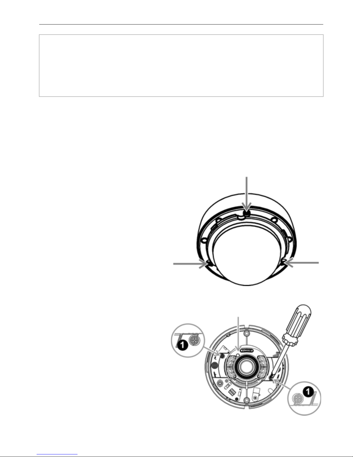
Preparing installation
The white design ring and dome
must be removed before
installation.
1. Loosen and remove the white
design ring by turning counter-
clockwise.
2. Loosen the three attachment
screws of the dome and
remove the dome.
The camera module may also be
removed to prevent damage to
the sensitive optic when
mounting the base plate.
3. Loosen both screws of the
camera module (1) and
carefully pull the camera
module upwards.
J
ESD warning
Important: Electrostatic charging! Before opening the housing and
working on cabling please discharge by contacting with earthed metal
parts to avoid damage to the device.
Camera module
5
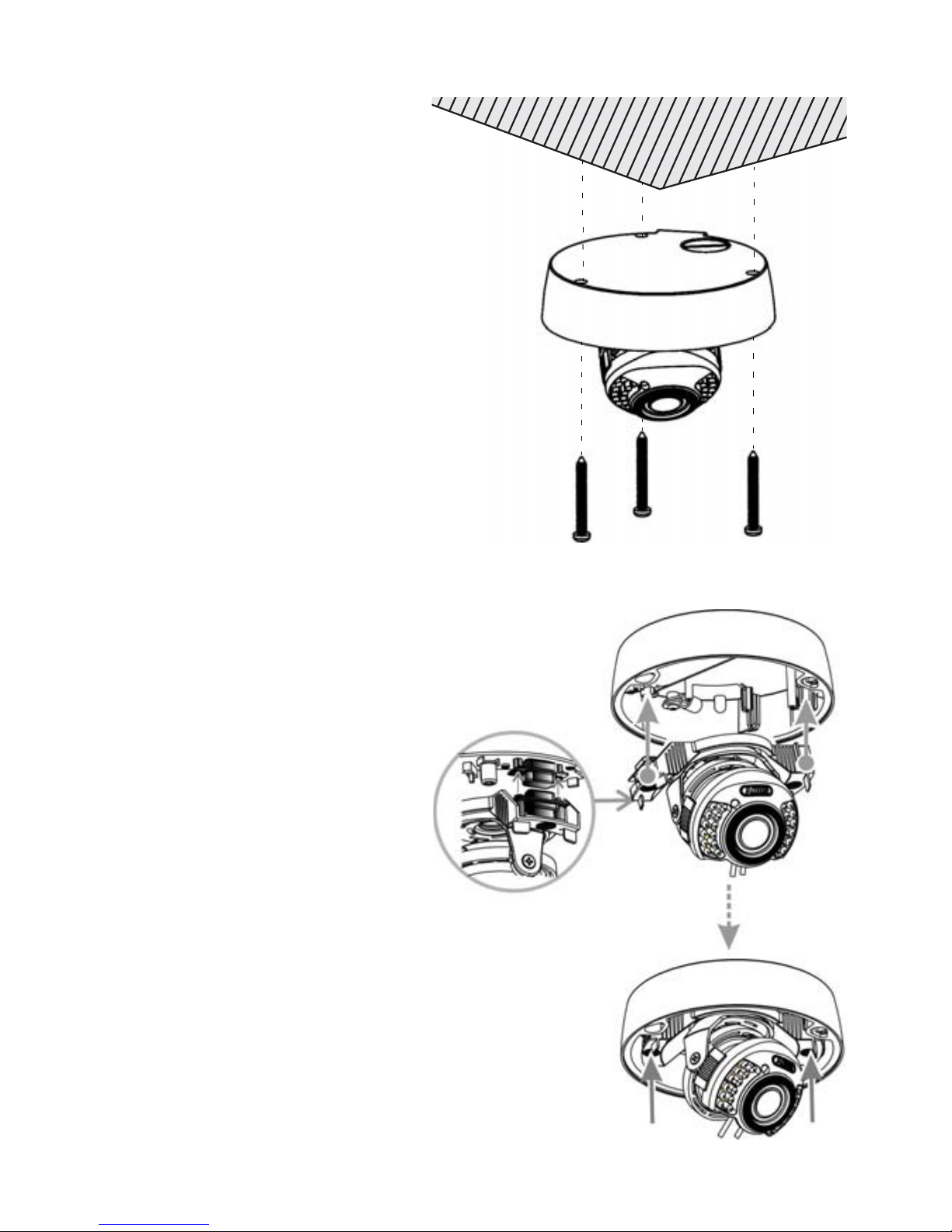
Mounting base plate
1. Position the accompanying
hole template at the intended
installation location and mark
the drilling holes.
2. Drill the mounting holes and
fasten the base plate with the
accompanying screws and
plugs.
Inserting camera module
1. Position the camera module
and base plate so that the
15-pole plug and 15-pole pin
jack face each other.
2. When the plug and pin jack
are one above the other,
press the camera module on
both sides towards the base
plate until the plug has
completely engaged into the
pin jack.
3. Tighten both screws of the
camera module.

6
Mounting dome
Before mounting the dome, carry out connection and start-up of the
camera.
Mounting the dome:
1. Pay attention to proper seating of the seal when mounting the dome.
2. Fasten the dome to the base plate with 3 screws.
3. Attach the white design ring and engage by turning clockwise.
Connection
1. Connect the 12 VDC power supply either via the circular connector or
via the accompanying terminal adapter.
If using the terminal adapter, comply with polarity specified.
2. The video signal is output via the BNC pin jack of the video output.
i
Permanent power supply
To ensure camera heating functionality, the camera must be permanently
connected to the power supply.
+ –
Terminal adapter
BNC video output
12 VDC power supply
7
Start-up
During start-up, a monitor can be connected to the secondary video output
for checking the camera image.
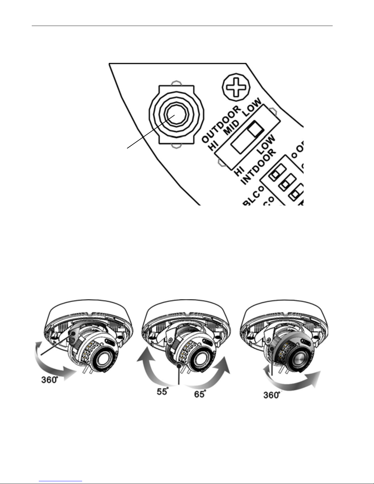
Aligning lens
The camera lens can be adjusted in 3 axes. Module rotation (1st and 3rd
axis) must not exceed 360°.
Video output
Swivelling Tilting Rotating
(1st axis) (2nd axis) (3rd axis)
8
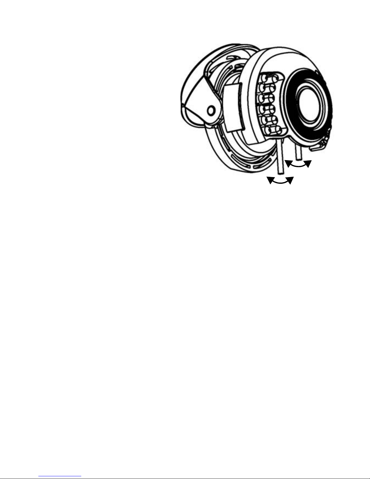
Setting focus and zoom
The zoom factor and focus each
have a setting screw on the
underside of the lens. These
screws also function as fixing
screws for the lens.
Setting zoom and focus:
1. Loosen the setting screws.
2. Carry out settings for zoom
and focus according to
requirements.
3. Secure the setting screws.
Zoom factor setting:
• W (WIDE) – wide angle of vision, zoom 0x (max.)
• T (TELE) – narrow angle of vision, zoom 3.75x (max.)
Focus setting:
• F (FAR) – far focus
• N (NEAR) – near focus
WT
N
F

9
Setting camera parameters
The following setting options are available on the device PCB:
Iris level potentiometer (1)
For setting the basis aperture of the auto iris lens
Slider switch for IR range (2)
The range of the IR light can be set in 3 steps
(HI: 20 metres; MID: 10 metres; LOW: 5 metres).
DIP switch (3)
• BLC – Background lighting compensation
(BLC=on; OFF=off)
• AGC – Automatic gain control
(AGC=normal; HI=AGC+6dB)
• DAY – Day/night switching
(AUTO=B/W mode at night;
DAY=colour mode also at night)
• IR – Infrared LED activation
(AUTO=automatic activation of IR LED in weak
light conditions;
IR OFF=IR LEDs permanently deactivated)
1
2
3

10
Technical data
Power supply: 12 V DC
Current consumption: max. 120 mA (IR off),
max. 310 mA (IR on)
Protection type: IP 66
Operating temperature: -20 °C to +50 °C
Humidity: 0 to 85%, non-condensing
Dimensions (HxØ): 99.5 x 145 mm
Standard: PAL
TV lines: 550 TVL
Image sensor: 1/3" Sharp HQ CCD
Pixels (effective): 752 (V) x 582 (H)
Signal-noise ratio: 48 dB
Minimal lighting (day): 0.03 lux @ F2.0
Minimal lighting (night): 0 lux @ F2.0
Day/night: IR swivel filter (ICR), colour / B/W
Lens: 2.8-10.5 mm, F2.0
IR LED: 24 LEDs, 850 nm
IR range: 5 / 10 / 20 m
Horizontal angle of vision: 27.4° to 101.8°
Electronic shutter: AI
Gain control (AGC): 20 dB / 26 dB (HI)
Background lighting
compensation: BLC
White balance: AWB, 2700 K to 9500 K
Video signal: 2 x FBAS, 1 Vss, 75 ohms (BNC, cinch)
Camera heating
Current consumption: 1 A
Switch-on current: max. 1,5 A
Switch-on temperature: < 8 °C
Switch-off temperature: >14 °C

11
Warranty
We provide a warranty in accordance with the statutory requirements.
Please send the device postage paid with error description via the
specialist trade to our central customer service centre.
Gira
Giersiepen GmbH & Co. KG
Service Center
Dahlienstraße 12
42477 Radevormwald
Gira
Giersiepen GmbH & Co. KG
Electrical Installation
Systems
P.O. Box 1220
42461 Radevormwald
Phone +49 (0) 2195 / 602 - 0
Fax +49 (0) 2195 / 602 - 339
www.gira.com
05/11 49 92 59
Table of contents
Other Gira Security Camera manuals


