Girard Products G-2000 User manual

GIRARD SYSTEMS
RV AWNING PRODUCTS
G-2000 CASSETTE PATIO AWNING
G-1500 DOOR AWNING
OWNERS MANUAL
INSTALLATION, OPERATION, ADJUSTMENT AND REPAIR
Rev. 010112
1361 CALLE AVANZADO, SAN CLEMENTE, CA 92673 (949)259-4000 FAX (949)276-5500

5 | Page
TABLE OF CONTENTS
BASIC SYSTEM OVERVIEW PG. 6
IMPORTANT REMINDERS PG. 7
QUICK START PG. 8
INSTALLATION MANUAL
PRODUCT DESCRIPTION PG. 9
TOOLS REQUIRED PG. 9
UNPACKING PG. 11
LAYOUT, MOUNTING THE BRACKETS PG. 12-15
BRACKET PLACEMENT CHART PG. 14
MOUNTING THE AWNING TO THE BRACKETS PG. 16
INSTALLATION OF COUPLED AWNINGS PG. 17-21
WEATHERSTRIPPING INSTALLATION PG. 22
ANEMOMETER INSTALLATION PG. 23
MOTION SENSOR PG. 24
TESTING AND ADJUSTMENTS
ADJUSTING MOTOR LIMIT SWITCHES PG. 25-26
ADJUSTING PITCH ARM HEIGHT PG. 27-28
TESTING THE ANEMOMETER PG. 29
ADJUSTING THE LEAD RAIL PG. 29
TROUBLESHOOTING GUIDE PG. 30-31
WARRANTY LABOR TIME GUIDELINES PG. 32
COMMON REPAIR PROCEDURES
MOTOR REPLACEMENT PG. 33-35
FABRIC REPLACEMENT PG. 36-38
ARM REPLACEMENT PG. 38-40
CARE AND MAINTENANCE GUIDE PG. 41-43
TECHNICAL DRAWINGS PG. 44-47

6 | Page
Basic System Overview
Your G-2000 and G-1500 Awnings consist of three main components:
1. Mechanical System – consisting of:
•The enclosure (or cassette) protects the fabric while closed.
•The roller tube which is mounted within the cassette.
•
The top cover or fabric rolled onto the roller tube and connected to the lead
rail that extends from the enclosure when the awning is opened.
•The folding arms that supports the lead rail and the fabric.
•The tubular motor which is mounted inside of the roller tube that allows the awning to
extend and retract.
2. Electronic controls – to power and operate the motor
•Anemometer (wind sensor) automatically retracts the awning in case of high wind that
may damage the awning system.
•Motion Sensor – This can be used in place of the anemometer.
•G-Links model GC136 Motor Control (single motor) to power and operate the motor.
•DC motor control.
•Wireless Motor – This motor does not require a motor control.
3. User Controls – for awning operation
GC136
98GC230

7 | Page
Important Reminders
Before using your awning make sure that all of your electrical circuits are operating correctly.
Recreational Vehicles can generate AC power from three separate sources; shore power
(hookup), generator, or inverter. The electrical system transfer switch in your vehicle will select
power for the awning as follows:
Shore Power – if connected;
Generator Power – if generator is running;
Inverter Power – batteries must be charged for inverter operation.
Your G-2000 is usually operated using a 110Volt AC motor. However, some awnings are
equipped with 12Volt DC motors. Your G-1500 is usually operated using a 12 Volt DC motor.
However, some awnings are equipped with a 110 Volt AC motor.
NOTICE
For a detailed description and user instructions for all
electronic and user controls please refer to the Girard Link
System (G-Link) manual supplied with the awning. If you
do not have a copy of the G-Link manual you may
download a copy from the Girard Systems website at
www.girardrv.com.

8 | Page
Extending/Retracting Awning
1. Programming the Remote Control
Wireless remote controls must first be programmed to your awning. Programming is usually
done at the factory and the user does not need to program his units.
2. Using the Remote Controls
G-Linkshand held Remote Controls are capable of controlling several awnings and use a
different communication channel for each awning. If your unit can control only two channels it
will indicate the channel selected using one of two LEDs above the control buttons. If your unit
can operate more than two channels an LCD display shows the number of the channel that is
currently selected. Your remote control will have the capability to control every Girard System
product installed on your coach up to a maximum of 15 units.
•To operate the hand held Remote Control you only need to press the button labeled
with the appropriate icon shown on the round rocker switch below the channels display.
•Channel selection is made by pressing the two icons marked on the round rocker switch
below the display.
•Pressing the center button will stop the motor.
•The custom LCD display, when activated by pressing any of the above buttons, shows
the active channel and the direction of motion.
•The operation of wall mounted switches is self-explanatory and normally UP indicates the
RETRACT function and DOWN the EXTEND function.

9 | Page
INSTALLATION MANUAL
Product Description
The G-2000 and G-1500 awning systems provide protection from the sun at a touch of a
button. The G-2000 and G-1500 awnings are built to your specifications with the highest
quality materials available, your units features:
•A standard motor that operates with a wireless motor control, or a wireless motor
that operates with an integrated motor control.
•An anemometer (wind sensor) or a Motion Sensor that will retract the awning to
prevent damage from the wind.
•A hand held Remote Control
•A wall mounted Remote Switch
•Options include; electronic automation controls to ensure proper closing at all
times, a control to retract all awnings when the vehicles’ motor is started, and
more….
Your G-2000 and G-1500
awnings controls’ use a RF (radio frequency) link to communicate
with each other. This simplifies the installation and maintenance by removing the need for
extensive wiring. This RF network is called the G-Link system. For more information please
refer to the G-Link manual that was included with your awning. All necessary power cables are
supplied with this product.
Getting Started
Tools required:
•Electric Drill
•Tape measure
•(2) ladders
•Socket wrench: 7/16” deep socket
•Chalk line
•Flat head screwdriver (small)
•Phillips screwdriver
•Caulking gun
•(2) tubes silicone caulking
•Drill bits: 1/8”, 3/8”, and 7/16”
•Allen wrenches: 5mm and 4mm
•Open-end wrenches: 10mm, 19mm
•Keyhole saw

10 | Page
Duration:4.5 hours (based on two installers)
Prior to beginning installation sequence:
1. Insert end of crank into manual override receiver, located at extreme end of awning.
2. Push in and rotate handle 1/4-turn clockwise. Let handle drop approximately 1/2”. (Handle
should lodge in receiver and awning may now be extended/opened.)
3. Extend awning approximately 12” by turning handle clockwise (see Fig. 1); confirm that
awning shoulders are in proper locations; make note of shoulder locations; and retract/close
awning by turning handle counter-clockwise.
NOTE: Roof mount awnings will have the manual override receiver positioned on the
top of the awning.
(FIGURE 1)
WARNING
ALL ELECTRICAL WORK MUST CONFORM TO APPLICABLE
ELECTRICAL CODES AND STANDARDS.
•Turn off power before beginning any electrical work.
•Please consult your RV’s wiring diagram to locate any wiring
prior to any drilling or any installation procedures.
•Ensure that placement of controls, cables, and wires are not
in any way obstructed. This can damage the components and
obstruct electrical current.
•Use only certified components.

11 | Page
FOR PERSONAL SAFETY AND QUALITY OF INSTALLATION, TWO
INSTALLERS ARE RECOMMENDED FOR THIS PRODUCT
A. UNPACKING
1. Before starting any of the installation procedures unpack the awning and inspect the
product for any possible damage that may have occurred during shipping.
2. Before starting any of the installation procedures review the length and motor
placement of your awning for correctness.
3. When you have determined that the product is to your satisfaction, remove the
mounting brackets and place the awning in a safe location while preparing the RV.
A. To remove the brackets locate the slide lock that retains the bracket to the
housing. (Figure. 2)
B. Using a 5mm Allen wrench loosen the set screws on the slide locks.
C. Once the set screws have been loosened the slide locks should slide freely,
clear the slide lock away from the bracket.
D. You should now be able to remove the bracket.
4. If you have discovered any damage or missing parts please follow the instructions in
the Warranty section of this manual.
(FIGURE 2)

12 | Page
B. LAYOUT, MOUNTING THE BRACKETS
ROOFMOUNT APPLICATION –The clearance needed for the roof mount application of
the G-2000 varies by manufacturer. The shape of the roof, the depth of installation, type
of roof mount bracket used and all other factors should be taken into consideration
when installing this product. It is up to the installer to find adequate structure to fasten
the roof mount brackets. All caution must be taken to weather seal all installation
perforations. Please consult Girard Systems if there are any questions regarding your
installation.

13 | Page
NOTE: Please consult your RV’s wiring diagram to ensure that no wiring will be
damaged while drilling the hole.
A. SIDEWALL APPLICATION
NOTE: Please take into consideration all possible clearances, and obstacles before
installing this awning. Items such as slide rooms, etc. vary from one manufacturer to
another. Please consult Girard Systems if there are any questions regarding your
installation.
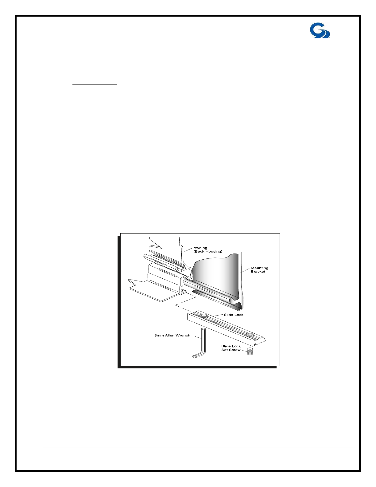
1. The mounting brackets and hardware used for this application are included with
your awning.
2. Determine the location for the final installation position of the awning, including
height to be installed.
3. Mounting brackets must be installed within two (2) inches of the ends of the
awning. Once you have determined the location of the two end brackets snap a
chalk line between the two points to ensure straightness of the installation. You
will be able to use this reference line to install the smaller center bracket at a
later time.
4. To find the location of the smaller center bracket please refer to chart on the
following page. NOTE: The location of the center bracket must fall directly
centered behind the center shoulder location. Failure to follow these
instructions will void the warranty of this product.
5. Now that you have located the bracket locations, using the bracket as your
template, mark the holes for fastening the bracket.
6. Using a 1/8” bit (8” long), pilot drill the centers of the marked holes. Inside of the
RV verify the locations of the backing plates. NOTE: Please consult your RV’s
wiring diagram to ensure that no wiring will be damaged while drilling the
hole.
7. Pre-drill six 7/16” holes per mounting bracket through the pilot holes.
8. Apply a liberal amount of silicone caulking around each hole before installing the
brackets.
9. Install the two (2) outer brackets, and then the center bracket (if required) with six
7/16” carriage bolts, washers, nylon nuts and two(2) backing plates per bracket.
(Figure 3) Tighten bolts and then apply silicone caulking to the top edge and both
sides of each bracket.
10.On the motor side of the awning drill a 7/16” hole for the awning motor cable to
enter the RV near the electrical source. Position the hole 1” to the left or right of
the bracket depending on motor location. Do not drill hole higher or lower than
the bracket. This will ensure that it will not be seen after the awning is installed.

14 | Page

15 | Page
11.On the motor side of the awning drill a 7/16” hole for the awning motor cable to
enter the RV near the electrical source. Position the hole 1” to the left or right of
the bracket depending on the location of the motor. Do not drill hole higher or
lower than the bracket. This will ensure it will not be seen after the awning is
installed.
12.
If you are using a 12V Motion Sensor locate the wire, then drill the
appropriate sized hole to rout the wire to your interior 12V source. Make sure to
seal any perforations made in the shell of the vehicle.
13.Locate the white wire grommet supplied with the awning. Place a fine bead of
silicone around the body of the grommet. Slide grommet into the 7/16” hole
previously drilled for the motor wire.
(FIGURE 3)

16 | Page
B. MOUNTING THE AWNING TO THE BRACKETS
1. Lift the awning into position for installing the awning on the brackets.
A. Ladders are usually sufficient; however, a scaffold or forklift may be used.
B. If using a forklift use all necessary caution to protect the surface of the
awning. Lift from the center of the awning to maintain product balance while
elevating.
2. Place the awning onto the brackets (Fig. 4 #8) while feeding the motor wire through
the white motor grommet. A small amount of lubricant may aid the feeding of the
wire. Make sure the grooves (Fig. 4 #2) of the awning are securely engaged into
the channels on the bracket. (Figure 4)
3. Secure the awning by moving the slide locks (Fig. 4 #6) along the bottom awning
track until they are located under their respective brackets. The final position of the
slide lock should be directly under the shoulder of the arm.
4. Once the final location of the slide locks has been achieved, tighten both set
screws on each slide lock with a 5mm allen wrench.
(FIGURE 4)

17 | Page
C. INSTALLATION INSTRUCTIONS FOR COUPLED AWNINGS
1. The 19” end brackets are installed 2” from the overall length of the awning. The
39” mounting bracket is located in the center, at the junction of the two awnings.
Additional brackets need to be located behind, and centered on the arms of each
awning.
2. After all the mounting brackets are firmly attached; place the motorized awning on
the mounting brackets. Place the slide locks under each plate, but do not tighten.
A fourth slide lock should be on the awning. This lock will be placed between the
two awnings once they are mounted. (Refer to Figure 16 in the Installation
Manual.)
3. Extend the motorized awning 20”–24”. Temporarily install the controller to the
motor and use the remote control.
(FIGURE 5)
NOTE: Do not remove the plastic from the non-motorized awning. Move the plastic away
from the area in contact with the mounting bracket.

18 | Page
4. Hang the non-motorized awning on the mounting brackets so it aligns up to the
drive shaft of the motorized awning. The slide locks should now be positioned on
the brackets and should not be locked to allow awnings to slide together freely.
(See Fig. 6)
5. Extend the non-motorized awning by 20” to 24”. To do so, use heavy cord or
straps on both ends of the awning to encircle the awning box, using enough to
allow the outward movement of the awning lead rail.
CAUTION: The arms are under extreme spring pressure. Once the plastic is cut, the
lead rail will instantly extend from the box! After the cord/straps are tied securely
around the awning box, carefully remove the plastic. The lead rail will then extend to
the length of the cord/straps. (See Fig. 6)
(FIGURE 6)
6. Extend the motorized awning past the non-motorized awning by about 8”.This will
allow the non-motorized awning with loose fabric to catch-up. Next you want to align
the black marks on gudgeons or align the poly ropes of the non-motorized awning
with the motorized awning.
These adjustments are to be made with the motorized awning, still keeping the
motorized awning ahead of the non-motorized. Once the alignment has been done
slide the awnings together. Then tighten all of the slide locks. Including the one
positioned in between both awnings. (See Fig 7)

19 | Page
(FIGURE 7)
7. Remove the cord/straps from the non-motorized awning. Extend the coupled awnings. The
fabric should be tight on both sides; if the motorized side is tighter, the awnings must be
realigned. See note on the last page for the realignment procedure.
8. Adjust the awnings for equal pitch and lead rail adjustment. (Refer to the Adjustments
section of this manual)
9. Move the lead rail guides away towards the center and make room to insert the lead rail
connector. The lead rail connector is installed in the lead rails. Center the connector bar
between the two awnings (approximately 8¾” per side). Remove the two Phillips screws and
drill one 9/64” hole into the lead rail using the lead rail connector as your template. Insert and
tighten the one Phillips screw and the tighten the hex screw on the same side. Draw the lead
rails together until they are joined and flush in the center. Using the attached lead rail
connector as your template drill a second 9/64” hole and tighten the other Phillips screw.
Tighten the remaining hex screw. (Figure 8)

20 | Page
(FIGURE 8)
10. At the juncture of the two awnings inside of the cassette are two glide angles. Move the
right glide angle 9” from the center and tighten until secure. (The awning should be open
about 24”–36” when performing this function.) With the removable bracket on the right, slide
the fabric onto the roller tube and roll the fabric over the TOP of the roller tube.
11. With the fabric on the roller tube, insert the fabric end into the lead rail connector. Slowly
unroll the fabric until you are up to the awning box. Place the right side into the glide angle
that you tightened down in step 10. (Figure 9)
12. Turn the left-hand side of the center roller tube towards the TOP (counter-clockwise) 13
complete rotations to tighten the spring. Place the left glide angle over the left side of the
center roller tube to hold it in place, and tighten down the left glide angle. (Figure 10)
13. Extend the awning to its full projection. If you have excessive sag in the center roller
fabric, repeat step 12 and add additional rotations.

21 | Page
NOTE: If the awnings do not align after completing step 7, release the tension on the
fabric using manual override. Then go to the end of the non-motorized side and remove
the side plate and the roller tube support bracket (Part #15 in the manual). Pull the
roller tube out of the middle insert and realign on the gudgeon or the poly cord.
Reassemble the awning and repeat steps 8–13. Readjust motor limits per this
Installation Manual.
(FIGURE 9) (FIGURE 10)

22 | Page
D. WEATHERSTRIPPING INSTALLATION -(SIDEWALL APPLICATION ONLY)
1. Trim weather stripping to the length of the awning and remove any overhang.
2. Make a small cut in the weather stripping to allow for the motor cord.
3. Apply generous beads of silicone where indicated in Figure 11.
4. Push weather stripping firmly into place.
5. Wipe off excess silicone.
(FIGURE 11)

23 | Page
E. ANEMOMETER – (Hardware Installation Only)
1. Place the anemometer on the roof of the vehicle. The unit can be mounted to a
horizontal, vertical, or an inclined surface. The rotor of the anemometer must be
pointing down. (Figure 12)
2. Position anemometer as follows:
A. On and parallel to the roofline
B. Near the awning to ensure the wind speed is measured accurately
C. Away from all obstructions (air conditioners, storage pods, etc.)
D. Orient the cups of the anemometer to the rear of the coach.
3. The anemometer operates remotely by sending a retract signal to the motor
control system of the awning.
4. The anemometer must have 12VDC power at all times when the awnings are
extended. The minimal power consumption will not affect the charge of the
batteries in any appreciable way. If there is a suitable source of 12VDC power
located on the roof then penetrating the shell of the vehicle will not be
necessary.
5. The power cord extends from the base of the unit and is suitable for outdoor use.
6. To obtain power from the inside of the vehicle a 3/8” hole must be drilled for the
Power wire. Drill the hole directly below where the power cord exits the anemometer
base.
7. Feed anemometer cord thru the 3/8” hole, leave 3-4” of slack. Silicone around the
wire to prevent any water intrusion.
8. Apply a bead of silicone where the footprint of the anemometer will be installed.
Mount the anemometer with two (2) screws. Silicone the perimeter of the base.
(FIGURE 12)
This manual suits for next models
1
Table of contents
Other Girard Products Accessories manuals
Popular Accessories manuals by other brands

TRENDnet
TRENDnet TEG-S24M2F supplementary guide

Panasonic
Panasonic MA6X125 (MA125) Specifications

Honeywell Home
Honeywell Home PROSiXPIR Quick installation guide

Tippkemper
Tippkemper CNS-506D operating manual

HYDAC International
HYDAC International CS1000 Series instruction manual

urmet domus
urmet domus 1033/132 manual