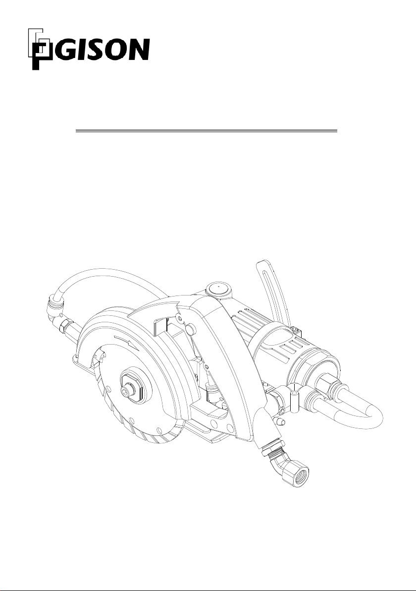
manuals.online logo
Brands
  1. Home
  2. •
  3. Brands
  4. •
  5. Gison
  6. •
  7. Saw
  8. •
  9. Gison GPW-227 User manual

Gison GPW-227 User manual

GISON
2
GPW-227
WET AIR CUTTING SAW
INSTRUCTION MANUAL
http://www.gison.com.tw
W
et Air Cutting S w GPW-227
ble of Contents
1
GISON
T ble of Contents
Import nt S fety Instruction
Read all instructions before using this tool. All
operators must be fully trained in its use and
aware of safety rules.
1) M inten nce
 Oil 3cc lubricant (SAE #10 or equiv lence)
through air inlet before connecting the
product to the air. Run the tool 15 seconds
to allow air circulating the oil and well
lubricate the cylinder. This will ensure top
performance and maximize durability of tool.
 Oil 3cc lubricant through air inlet after use
and run the tool 5 seconds before storage.
 Clear dry air allows the product perform at
its best and extends the product life. A Filter/
Regulator/Lubricator set is highly
recommended.
 If the tool is in unusual condition, shut it off
and disconnect its air hose immediately. Put
a warning sign on the product until it gets
repaired.
 Product repairing needs professional training
and tool. Do not attempt to disassemble the
product or it might be damaged.
2) User
 The user must be well trained and physically
able to operate the product and aware of
safety regulation.
 Use personal safety equipment such as
goggle, earmuffs, mask apron.
 Maintain a balanced body position and
secure distance. Do not wear jewelry or
loose clothing. Helmet is required if you wear
long hair.
3) Compressed Air
 Do not operate the product with excess air
pressure; standard air pressure is 90 psi (6.2
bar or 6.3kg/cm2).
 Always shut off air supply, drain hose of air
pressure and disconnect product from air
supply before changing accessories, making
repairs or when the tool is not in use.
 Never direct air or product at yourself or
anyone else.
 Whipping hose can be extremely dangerous
and causes serious injury. Always check for
damaged or loose hoses and fittings.
4) Product
 Do not adapt the product for other purpose; it
might harm the product and the user.
 Do not adapt or remove the switch, level or
any other component of the product; it might
result in malfunctioning and harm the user.
 Do not use quick connect coupling on the
product directly; use it only on the hose end.
 The product is not insulator; keep away from
electricity.
5) Accessories
 Please use proper accessories, improper or
unqualified accessories may damage the
product, deteriorate performance and do
harm to user.
 When replacing the accessories, use the tool
attached with the product. Improper tool or
incorrect ways of handling the tool (such as
strike) may damage it.
6) Workpl ce
 Slip, trip fall are major causes of serious
injury or death; be aware of excess hose left
on the walking or working surface.
 Workpiece must be fixed firmly; always keep
no miscellaneous objects that could interfere
with the operation.
Import nt S fety Instruction
………..…………………………………………………..
1
Controls & Connections
………………………………………………………..…………
2
Before Oper tion
………….……………………………………………………………………
3
Getting St rt
………………………………………………………………………………………
4
P rts List
……………………………………………………………………………………………
7
EC Decl r tion of Conformity
…………………………………………..………………
9
W
et Air Cutting S w GPW-227
ble of Contents
GISON
2
1
3
8
4
7
6
2
Top View 6
5
CONTROLS & CONNECTIONS
No Description
1 Fix Screw
2 Trigger
3 Trigger Lock
4 Air Inlet
5 Adjust Screw
6 Butterfly Screw
7 W ter V lve Knob
8 W ter Inlet
W
et Air Cutting S w GPW-227
Instruction M nu l
3
GISON
BEFORE OPERATION
Check the followings first:
1. Make sure the workplace is suitable to perform cutting work.
2. Verify if the capacity of air compressor could provide sufficient airflow rate for the tool.
3. Drain the water in compressor tank; fill the lubricator with oil (SAE#10 or equivalence)
and make sure no rust or problem found in the compressor.
4. Check and adjust the operating pressure of compressed air; the best work pressure is
90 psi (6.2 bar or 6.3kg/cm
2
); excess air pressure may result in over-speed hazard.
Prep ring Connections:
WARNING
M ke sure the following procedures h ve been complied
with respective instruction before oper tion
1. Workplace for operating cutting saw must comply with related safety health regulation.
2. Connect tool to the air hose, water hose and air exhausting hose as the following steps:
2-1 Connect water hose to water inlet: dip the hose end (about 3 cm long) in 95-100
o
C hot
water for 10 seconds to soften the hose end; this could facilitate the hose to be easier
connected to the water inlet. Be careful not to scald by the hot water.
2-2 Make sure the air hose have been properly connected to air inlet of tool.
3. Connect air hose to air inlet:
3-1 Remove any dust or particle found in the air hose and adapters to prevent from
feeding particles into the tool and result in possible damage.
3-2 Verify if the adapters are firmly secured on the hose; connect the hose between air
compressor and tool.
W
et Air Cutting S w GPW-227 Instruction M nu l
GISON
4
97
96
95
100 99
Base
Blade
43
43 Blade
A aerial view for base
GETTING START
Prepare the First Cutting:
WARNNING
 To prevent from ny possible injury to the user or d m ge the workpiece, lw ys keep
the cutting bl de w y from workpiece before opening the trigger.
 M ke sure the oper tors keep in s fety dist nce from the cutting bl de before
feeding the ir to the tool.
WARNNING
 Alw ys disconnect the ir hose d pter before ch nging the cutting bl de, rep iring
the tool or when the tool is not in use.
 Use person l s fety equipment such s goggle, e rmuffs, m sk & pron in work.
 Choose proper cutting bl de for different m teri l of the workpiece.
 Never use cutting bl de m rked with speed lower th n r ting speed of tool
 Never use broken or d m ged cutting bl de.
 If the tool drops by ccident, check nd verify c refully to m ke sure the tool works
norm lly before proceeding your work
A. Inst ll Cutting Bl de
1. Stop the nut (95) with main shaft wrench (99)
2. Use Allen wrench (100) to loosen fix screw (97) clockwise, then remove spring
washer (96) and nut (95).
3. Take the cutting blade away from the arbor and install a new blade
4. Put back nut (95), spring washer (96) and fasten fix screw (97) counter-clockwise.
5. After installation, turning blade by hand to ensure blade and (36
th
) Water Exit have
been installed properly and matching.
W
et Air Cutting S w GPW-227
Instruction M nu l
5
GISON
8
7
6
Top View 6
5
B. Adjust Cutting Depth
1. Loose the butterfly nut (6) to set the blade to the
required cutting depth and fasten the butterfly nut
2. Use Allen wrench (100) to set the adjust screw (5)
positioned on bottom plate to prevent butterfly
nut (6) from loosing during long period of operation
C. Feed W ter
Connect water hose to water inlet (8)
and adjust the water valve knob (7) to
feed water to the cutting blade.
W
et Air Cutting S w
GPW-227 Instruction M nu l
GISON
6
1
3
8
4
2
D. Feed Compressed Air
1.
Check and verify if the fix screw (1) is tightly fastened.
2.
Connect air hose to air inlet (4)
PRECAUTION
Prior to cutting, tri l run the tool with free lo d for few seconds to visu lly check if cutting
bl de is fixed properly nd the tool is running smoothly. Stop the tool immedi tely if ny
bnorm l sound or vibr tion is found. Re-check the inst ll tion of cutting bl de or
consult with distributor for further ssist nce.
3.
Press trigger (2) to check if the tool start running; keep your hand away from the cutting
blade to prevent from injury.
4.
To run tool continuously, first hold trigger (2) and trigger lock (3), second release trigger;
then the tool can now work continuously; it eases finger off the long pressing fatigue.
5.
Press trigger (2) to release trigger lock (3) when you need to return normal operation.
W
et Air Cutting S w
GPW-227
Instruction M nu l
7
GISON
P rts List
W
et Air Cutting S w
GPW-227 Instruction M nu l
GISON
8
* To order parts, please mark both P rts No. and Description. 2012/8/30
Qty
3
2~3
1
4
1
1
1
3
1
1
2
1
1
1
1
1
1
5
5
1
1
1
1
1
1
1
1
1
1
1
1
1
1
1
1
Description
Allen Screw
Joint Washer
Quick Joint, L-type
Screw
Angle Setting Ring
Fix Plate
Coupling Nut
Allen Screw
Quick Joint
Exhaust Cover
Self Tapping Screw
Screw
Cap
Joint Piece
Base
Support Frame
Angle Index
Screw
Nut
Allen Screw
Nut
Flat Washer
Butterfly Nut
Water Pipe
Air Inlet Pipe
Disc Receiver (22 mm)
Disc Nut
Spring Washer
Allen Screw
Air Joint
Bushing
Stopper
Grease Hole
Stop Spanner
Allen Wrench
Part No.
CAP007
227A30600
227SQL1001
MT007
227A60000
227A40100
227A40200
CAP024
227SQC1001
227A40300
TP3X10
MT001
221A20503
227A10400
227A10501
227A10300
227A60100
MC010
NH4
CAP040
NH5
T5X10
MR5X10
227AH06
227AH10
227A20400N
227A20401
SPW6
CAP041
227TB4502
227A10401
227A60200
221A10800
301T60000
420068
Item
73
74
75
76
77
78
79
80
81
82
83
84
85
86
87
87
-1
87
-2
87
-3
87
-4
88
89
90
91
92
93
94
95
96
97
98
99
100
101
102
103
Qty
1
1
1
1
1
1
1
1
1
2
3
2
1
1
1
1
1
1
2
1
1
1
1
1
1
1
2
1
1
1
1
1
1
1
1
1
Description
Spacer
Spiral Gear
Retaining Ring
Ball Bearing
Gasket
Disc Guard
Shroud
Water Exit
Water Exit Nut
Quick Joint, L-type
Allen Screw
Allen Screw
Handle
Spring Pin
Spring
Push Button
Fix Nut
Trigger Lock
Spring Pin
Trigger
Pin
Pin
O-Ring
Spring
Air Inlet Screw
Water Valve Seat
Bushing
Ball Valve
Copper Bushing
Spring
Water Valve Joint
Shaft
Screw
Spring Pin
Water Valve
Screw
Part No.
227A10600
227A10900
C12
B606ZZ
227A10201
227A70200
227A70201
227A7000
1
227A70100
227SQL601
CAP017
CAP016
227A30100
SP013
S055
227A30400
227A30500
227A30200
SP016
227A30300
227A30101
832059
OR034
S022
832057
227A50000
221A20100
221A20101
227A50300
S0
73
227A5020
0
221A20200
227A50100
SP001
227A50400
MT005
Item
37
38
39
40
41
42
-1
42-2
43
44
45
46
47
48
49
50
51
52
53
54
55
57
58
59
60
61
62
63
64
65
66
67
68
69
70
71
72
Qty
1
1
2
1
1
1
1
4
1
1
1
1
1
1
1
1
1
1
1
1
1
1
1
1
1
6
1
1
1
1
1
1
1
1
1
1
Description
Body
Front Plate
Ball Bearing
Ball Bearing
Rotor
Cylinder
Spring Pin
Blade
Rear Plate
Pinion Gear
Rubber Cap
O-Ring
Lock Ring
Spacer
Main Shaft
Bearing
Key
Bevel Gear
Wave Washer
Retaining Ring
Ball Bearing
Key
Spiral Gear
Retaining Ring
Gear Box
Allen Screw
Spring
Flat Washer
Allen Screw
Gear Shaft
Ball Bearing
Oil Seal
Gear Seat
Wave Washer
Retaining Ring
Key
Part No.
227832001
829023
B608ZZ
B6201
ZZ
832024
829022
GH
SP025
829019
829018
832015
829015
OR032
227A40000
832019
227A10000
B6202ZZ
KR002
832010B
WW10
C10
B626ZZ
KC004
227A10800
C8-I
227A10100
CAP005
S072
T4X8
CAP033
227A10700
B6201ZZ
SG019
227A10200
WW24
R32
KR006
Item
1
2
3
4
5
6
7
8
9
10
11
12
13
14
15
16
17
18
19
20
21
22
23
24
25
26
27
28
29
30
31
32
33
34
35
36
W
et Air Cutting S w
GPW-227
Instruction M nu l
9
GISON
EC DECLARATION OF CONFORMITY
Manufacturer : GISON MACHINERY CO., LTD.
Address : No.6, Alley 105, La e 68, Sec.2, Si a Road, Wurih, Taichu g 414, Taiwa
Tel: 886-4-23353202 Fax: 886-4-23352252
Declares that the machinery described :
Model : GPW-227
Name : Wet Air Cutti g Saw
Conforms to the following directives : Machi ery Directive 2006/42/EC
Refer to the following standards : EN 792-7
Place and Date of Issue : GIS N Machinery Co., Ltd.
March. 22, 2010
Signature of Issuer
________________________
Freddy Lin / President
W
et Air Cutting S w
GPW-227 Instruction M nu l
GISON
10
PNEUMATIC TOOLS SAFETY INSTRUCTION
The goal of GISON M chinery Co., Ltd. is to
produce tools that help you work safely and
efficiently. The most important safety device for
this or any tools is YOU, Your care and good
judgment are the best protection against injury, All
possible hazards cannot be covered here, but we
have tried to highlight some of the important ones.
Air Supply nd Connection H z rds
 Air under pressure can cause severe injury.
 Be sure that switch is at "OFF" position before
connect with air supply system.
 Always shut off air supply, drain hose of air
pressure and disconnect tool from air supply
when not in use, before changing accessories
or when making repairs.
 Never direct air at yourself or anyone else.
 Whipping hoses can cause serious injury,
always check for damaged or loose hoses and
fittings.
 Do not use quick disconnect couplings at tool.
See instruction for correct set-up.
 Whenever universal twist couplings are used,
lock pins must be installed.
 Do not exceed maximum air pressure of 90
psi/6.2 bar or as stated on tool nameplate.
Projectile H z rds
 Always wear impact resistant eye and face
protection when involved with or near the
operation, repair or maintenance of the tools or
changing accessories on the tool.
 Be sure all others in the area are wearing
impact-resistant eye and face protection.
 Even small projectiles can injure eyes and
cause blindness.
 Accessory bursts may be to cause serious
injury.
Ent nglement H z rds
 Keep away from rotating spindle and
accessory.
 Do not wear jewelry or loose clothing.

Scalping can occur if hair is not kept away from
tool and accessories.
 Choking can occur if neckwear is not kept away
from tool and accessories.
Oper ting H z rds
 Avoid direct contact with rotating spindle and
accessory to prevent cutting of hands or other
body parts. Wear gloves to help protect
hands.
 Do not disable the safety lock off feature on
the throttle lever.
 This tool and its accessories must not be
modified.
 The liability of manufactory lapses if the user
uses spare parts that are not idential with the
original.
 Operators and maintenance personnel must
be physically able to handle the power of the
tool and capable of performing the job task.
Workpl ce H z rds
 Slip/Trip/Fall is a major cause of serious injury
or death. Be aware of excess hose left on the
walking or work surface.
 High sound levels can cause permanent
hearing loss. Use hearing protection as
recommended by your employer.
 Regarding the dangers to vibration. User
have to obey the Labor Safe operational
instruction that depend on defferent country
rule to setting.
 Maintain a balanced body position and secure
footing.
 Repetitive work motions, awkward positions
and exposure to vibration can be harmful to
hands and arms, if numbness, tingling pain or
whitening of the skin occurs, stop using tool
and consult a physician.
 Avoid inhaling dust or handling debris from
work process that can be harmful your health.
 Operators and maintenance personnel must
be physically able to handle the bulk weight
and power of this tool.
 This tool is not intended for use in explosive
atmospheres and is not insulated for contact
with electric power sources.
DO NOT DISCARD - GIVE TO USER
W
et Air Cutting S w
GPW-227
Instruction M nu l
11
GISON
GISON MACHINERY CO., LTD.
No.6, Alley 105, Lane 68, Sec.2, Sinan Rd., Wurih, Taichung 414, Taiwan
Tel: +886-4-23353202 Fax: +886-4-23352252
E-Mail: gison@seed.net.tw Website: http://www.gison.com.tw
Printed in 23 July, 2013

Other Gison Saw manuals

Gison GPW-216C User manual

Gison

Gison GPW-216C User manual

Gison GPW-215C User manual

Gison

Gison GPW-215C User manual

Popular Saw manuals by other brands

MasterForce 241-0431 Operator's manual

MasterForce

MasterForce 241-0431 Operator's manual

Draper ABSSG Instructions for

Draper

Draper ABSSG Instructions for

Power Fist 8968828 user manual

Power Fist

Power Fist 8968828 user manual

Tack life PMS03 user manual

Tack life

Tack life PMS03 user manual

Delta 28-206 instruction manual

Delta

Delta 28-206 instruction manual

woodmizer SLR Safety, Operation, Maintenance & Parts Manual

woodmizer

woodmizer SLR Safety, Operation, Maintenance & Parts Manual

sunjoe SWJ701E Saw Joe Operator's manual

sunjoe

sunjoe SWJ701E Saw Joe Operator's manual

Lumberjack SS405 Safety and operating manual

Lumberjack

Lumberjack SS405 Safety and operating manual

WorkPro WG894E manual

WorkPro

WorkPro WG894E manual

Power Fist Air Nibbler user manual

Power Fist

Power Fist Air Nibbler user manual

Emax EATCO30S1P Operator's manual

Emax

Emax EATCO30S1P Operator's manual

woodmizer LT20 Series Safety, Setup, Operation & Maintenance Manual

woodmizer

woodmizer LT20 Series Safety, Setup, Operation & Maintenance Manual

Far Tools LS 505D Original manual translation

Far Tools

Far Tools LS 505D Original manual translation

Delta Horizontal Band Saw Safety manual

Delta

Delta Horizontal Band Saw Safety manual

Power Fist 8069627 owner's manual

Power Fist

Power Fist 8069627 owner's manual

woodmizer 1996 LT25 Safety, Setup, Operation & Maintenance Manual

woodmizer

woodmizer 1996 LT25 Safety, Setup, Operation & Maintenance Manual

Central Pneumatic CENTRAL PNEUMATIC PROFESSIONAL 98525 Set up and operating instructions

Central Pneumatic

Central Pneumatic CENTRAL PNEUMATIC PROFESSIONAL 98525 Set up and operating instructions

Power Fist 3042597 user manual

Power Fist

Power Fist 3042597 user manual

manuals.online logo
manuals.online logoBrands
  • About & Mission
  • Contact us
  • Privacy Policy
  • Terms and Conditions

Copyright 2025 Manuals.Online. All Rights Reserved.