Glenair 050-352 User manual

BF15U2-2330
THIS COPYRIGHTED DOCUMENT IS THE PROPERTY OF GLENAIR, INC. AND IS FURNISHED ON THE CONDITION THAT IT IS NOT TO
BE DISCLOSED, REPRODUCED IN WHOLE OR IN PART, OR USED TO SOLICIT QUOTATIONS FROM COMPETITIVE SOURCES, OR USED
FOR MANUFACTURE BY ANYONE OTHER THAN GLENAIR, INC. WITHOUT WRITTEN PERMISSION FROM GLENAIR, INC. THE INFORMATION
HEREIN HAS BEEN DEVELOPED AT GLENAIR'S EXPENSE AND MAY BE USED FOR ENGINEERING EVALUATION AND INCORPORATION
INTO TECHNICAL SPECIFICATIONS AND OTHER DOCUMENTS WHICH SPECIFY PROCUREMENT OF PRODUCTS FROM GLENAIR, INC.
050-352
PRODUCT BRIEF
10MBPS-200 MBPS
PRINTED CIRCUIT BOARD (PCB) MOUNT TRANSCEIVER
1310NM FP TRANSMITTER,PIN TIA RECEIVER
SMALL &COMPACT WITH RUGGED CONSTRUCTION FOR
HARSH ENVIRONMENTS
REV
DESCRIPTION
DATE
APPROVED
2
Preliminary
06/05/2015
SZ
3
Updated description on Pin Assignment Table
01/04/2016
SZ
4
Add ECCN
05/26/2016
RAS
5
Change PRBS Specification to 27-1
10/12/2016
SZ/GC
6
Replace "mm" with "um" on I2C table
11/11/2016
SZ/GC
7
Edit Bag and Tag Labeling
12/12/2016
RAS/GC
8
Remove incorrect reference to ATMEL AT240C01A, added optional I2C addressing
02/28/2017
RAS/GC
9
Corrected datasheet - removed Receiver power monitoring language
6/11/2018
RAS/SZ

©2015 Glenair, Inc. REV: 9 US Cage Code 06324 Printed in USA
GLENAIR, INC. ∙1211 AIR WAY ∙GLENDALE, CA 91201-2497 ∙TEL: 818-247-6000 ∙FAX: 818-500-9912
www.glenair.com PAGE 2 of 15 E-mail: [email protected]
050-352 Product Brief
PCB Mount Transceiver
10 Mbps –200 Mbps, SMF, 3.3V
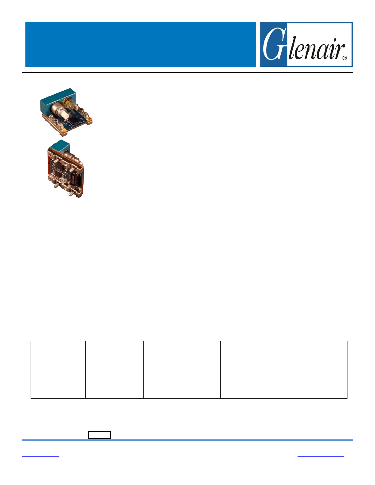
PCB Mount Fiber Optic Transceiver, 10Mbps-200Mbps, SMF, 3.3V
Glenair 050-352, is a ruggedized harsh environment PCB Mount Transceiver
with electrical and optical functionality equivalent to SFP transceivers but with
mechanical design that is suited to the harsh temperature and vibration environments
found in Military, Aerospace, Railway, Oil and Gas, and Industrial applications. The
PCB mount optical transceivers also support optional Digital Monitoring Interface (DMI)
features in accordance with SFF 8472. The Transceiver is comprised of a transmitter
section and a receiver section that resides on a common package and interface with a
host board through a high speed electrical connector.
The transmitter section includes the Transmitter Optical Subassembly (TOSA)
and Laser driver circuitry. The TOSA, containing a 1310nm FP laser is located at the
optical interface and mates with the GC optical connector. The TOSA is driven by a
laser driver, which converts differential logic signals into an analog drive current.
The receiver section includes the Receiver Optical Subassembly (ROSA) and
amplification/quantization circuitry. The ROSA, containing a PIN photodiode and trans-
impedance preamplifier, is located at the optical interface and mates with the GC
optical connector. The ROSA is mated to a limiting amplifier IC that provides post-
amplification and quantization. Also included is a Loss Of Signal (LOS) detection
circuit.
HOW TO ORDER Table 1 Part Number Development Options
Part Number
Two Wire Address
Data Rate
Temperature**
Screw Length**
(Mod Code)
050-352
PCB Mount
Transceiver, SMF,
1310nm
Blank = A2h
Other Options:
C0, C2, C4, C6, C8,
CA, CC, CE, D0, D2,
D4, D6, D8, DA, DC,
DE
-1-D = 10 Mbps - 200 Mbps
Blank = Standard
Blank = Standard
-954-xxx = IAW Mod
Code 954
-954A-xxx = IAW Mod
Code 954A
Example: 050-352C0-1-D
PCB Mount Transceiver, SMF, 1310nm, Two Wire Address = C0h, Data Rate = 10 Mbps –200 Mbps,
Standard Temperature Range, Standard Screw Length
**Temperature and Screw Length Mod Codes will not be added onto Digital Memory ID (See Table 9)
KEY FEATURES/BENEFITS
SFP Compatible Electrical I/O signal levels
1310nm FP laser to support up to 200Mbps
PIN PD to support high sensitivity up to 200Mbps
Glenair Rugged GC Optical connector
High Operational Shock (650 g) &
Vibration (54 g rms) –test reports available
Transceiver is securely mounted with screws to
PCB to ensure excellent shock and vibration
performance
High-Speed Electrical plug-in connector eliminates
the need for soldering & enables ease of servicing
Captive screws to simplify logistics and assembly
Compact size: Approx 0.8” x 0.9” x 0.5”
-40°C to +85°C Operating Case Temperature
Glenair fiber jumpers connect from transceiver to
any Glenair Mil/Aero Fiber Optic Connector Style
Evaluation fixtures available
Optional Digital Diagnostic and Monitoring (DMI)
based on SFF-8472, enables monitoring of:
oTX optical power, Laser bias current,
Temperature, Supply voltage
APPLICATIONS
Harsh Environment such as: Airborne, Tactical,
Railway, Industrial, Oil and Gas and Shipboard
applications
oEthernet, Fast Ethernet, FDDI

©2015 Glenair, Inc. REV: 9 US Cage Code 06324 Printed in USA
GLENAIR, INC. ∙1211 AIR WAY ∙GLENDALE, CA 91201-2497 ∙TEL: 818-247-6000 ∙FAX: 818-500-9912
www.glenair.com PAGE 3 of 15 E-mail: [email protected]
050-352 Product Brief
PCB Mount Transceiver
10 Mbps –200 Mbps, SMF, 3.3V
Ratings and Specifications
TABLE 2ABSOLUTE MAXIMUM RATINGS
Parameter
Symbol
Min
Typ
Max
Units
Notes
Storage Temperature
Ts
-55
+100
°C
Supply Voltage
Vcc
-0.4
3.8
V
VccT & VccR may not differ by
more than 0.5V
TABLE 3OPERATING CONDITIONS
Parameter
Symbol
Min
Typ
Max
Units
Notes
Operating Temperature, Case
Top
-40
+85
°C
Supply Voltage
Vcc
3.135
3.3
3.465
V
Supply Current
Icc
180
250
mA
Typical @ +85°C
Power Supply Noise (Peak-Peak)
Vcc_ripple
100
mV
TABLE 4ELECTRO-OPTICAL CHARACTERISTICS –TRANSMITTER (TOP UNLESS NOTED OTHERWISE)
Parameter
Symbol
Min
Typ
Max
Units
Notes
Optical Output Power
POUT
-14
-4
dBm
1310nm FP, SMF
Extinction Ratio
Er
8
10
dB
Optical Wavelength
λOUT
1260
1300
1380
nm
Spectral Width, rms
Δλ
4
nm
Transmitter Differential Input Impedance
Zin
100
Ohms
AC coupled Internally
Differential Input Voltage
Vin_d
250
2200
mVp-p
LVPECL, 100 ohm
TABLE 5ELECTRO-OPTICAL CHARACTERISTICS –RECEIVER (TOP UNLESS NOTED OTHERWISE)
Parameter
Symbol
Min
Typ
Max
Units
Notes
Sensitivity, BER 10-10, PRBS 27-1, Er 10 dB
PIN
-34
-32
dBm
PIN PD @ 125Mbps
Overload, BER 10-10, PRBS 27-1
PIN
-3
dBm
@125Mpbs
Optical Wavelength
λIN
1100
1600
nm
Receiver Differential Output Impedance
Zout
100
Ohms
AC coupled internally
Differential Output Voltage Swing
Vout_d
400
2000
mVp-p
LVPECL, 100 ohm
LOS Assert Level
LOS
-35
dBm
@ 125 Mbps
LOS Hysteresis
LOSHYS
1.5
3
dB
@ 125 Mbps

©2015 Glenair, Inc. REV: 9 US Cage Code 06324 Printed in USA
GLENAIR, INC. ∙1211 AIR WAY ∙GLENDALE, CA 91201-2497 ∙TEL: 818-247-6000 ∙FAX: 818-500-9912
www.glenair.com PAGE 4 of 15 E-mail: [email protected]
050-352 Product Brief
PCB Mount Transceiver
10 Mbps –200 Mbps, SMF, 3.3V
Ratings and Specifications (cont’d)
TABLE 6COMPLIANCE SPECIFICATIONS
CHARACTERISTIC
Standard
Condition
Notes
Mechanical Shock
MIL-STD-810
Para. 516.6, proc. I, 650g
0.9 ms operating
Mechanical Vibration
MIL-STD-810
Para. 514.6, 40g rms
Random, operating
ESD
MIL-STD-883
1000V HBM
Flame Resistance
MIL-STD-1344
Method 1012, Cond. B
30 seconds
Altitude
Altitude, 25Kft
Altitude, 70Kft
Decompression
Overpressure
RTCA DO160 G
Section 4.6.1 Category B1
Section 4.6.1 Category E1
Section 4.6.2 Category A2
Section 4.6.3 Category A1
Operating Altitude, 25,000 ft
Operating Altitude, 70,000 ft
Operating Altitude, 45,000 ft
28 psia
Damp Heat
RTCA DO160G
MIL-STD-1344
Section 6 Category A
Method 1002.2, Cond. B
48 hours, Non-operational
10 cycles, 24 hours, Operational
Eye Safety
CDRH and IEC-825
Class 1 Laser Product
TABLE 7MATERIAL/FINISH
Item
Material/Finish
PCB
FR4
PCB flex
FR4 & Polyimide
Railings
Aluminum 6061-T6 per ASTM-B221/B211M or Equivalent
Screws
CRES Type, 302, 303, 304, 305, or 316
Optical Ferrules & Sleeves
Zirconia, Ceramic
Solder type
RoHS compliant Sn95/Sb5 (232°C melting temp) &
RoHS compliant Sn96.5/Ag3.0/Cu0.5 (217° melting)

©2015 Glenair, Inc. REV: 9 US Cage Code 06324 Printed in USA
GLENAIR, INC. ∙1211 AIR WAY ∙GLENDALE, CA 91201-2497 ∙TEL: 818-247-6000 ∙FAX: 818-500-9912
www.glenair.com PAGE 5 of 15 E-mail: [email protected]
050-352 Product Brief
PCB Mount Transceiver
10 Mbps –200 Mbps, SMF, 3.3V
FIGURE 1 - OUTLINE DRAWING CONTINUED (MARKING)
LABELING:
Each unit will be shipped in an antistatic bag. The label on the antistatic bag shall be at a minimum Arial size 10
black font and contain at a minimum the following information:
ANTISTATIC BAG LABEL:
Glenair
Cage Code: 06324
PN: 050-352XX-X-X
Rev: X
QTY: X
J/N: X
D/C:X
S/N*: XXXXXX
*If QTY is more than 1, there is no S/N
Each unit will be marked, either with a label or laser engraving, as follows:
Marking font to be Arial, greater than .08 inches in height.
Marking:
FIRST LINE OF TEXT
Glenair
Serial Number (6 digits)
SECOND LINE OF TEXT:
Part number
Example
GLENAIR SN123456
050-352C0-1-D

©2015 Glenair, Inc. REV: 9 US Cage Code 06324 Printed in USA
GLENAIR, INC. ∙1211 AIR WAY ∙GLENDALE, CA 91201-2497 ∙TEL: 818-247-6000 ∙FAX: 818-500-9912
www.glenair.com PAGE 6 of 15 E-mail: [email protected]
050-352 Product Brief
PCB Mount Transceiver
10 Mbps –200 Mbps, SMF, 3.3V
FUNCTIONAL DESCRIPTION
TRANSMITTER SECTION
Transmit Disable (TX_Disable, pin 10)
The transmitter section of the transceiver accepts a TTL and CMOS compatible transmit disable control signal input that
shuts down the transmitter optical output. A high signal disables the transmitter while a low signal allows normal
transceiver operation. Also Laser is disabled when TX Disable is open.
RECEIVER SECTION
Receiver Loss of Signal (LOS, Pin 20)
The Loss of Signal (LOS) output indicates an unusable optical input power level. The post-amplification IC includes
transition detection circuitry which monitors the ac level of incoming optical signals and provides a TTL/CMOS compatible
status signal to the host. A low LOS logic level indicates the presence of an optical input while a high LOS logic level
indicates an unusable optical input. The LOS thresholds are factory-set so that a high output indicates a definite optical
fault has occurred (e.g. failed transmitter, broken or disconnected fiber connection to the transceiver, etc.). The LOS can
also be monitored via the 2-wire serial interface (address A2h, byte 110, bit 1).
Figure 2 PCB mount Transceiver Block Diagram

©2015 Glenair, Inc. REV: 9 US Cage Code 06324 Printed in USA
GLENAIR, INC. ∙1211 AIR WAY ∙GLENDALE, CA 91201-2497 ∙TEL: 818-247-6000 ∙FAX: 818-500-9912
www.glenair.com PAGE 7 of 15 E-mail: [email protected]
050-352 Product Brief
PCB Mount Transceiver
10 Mbps –200 Mbps, SMF, 3.3V
FUNCTIONAL I/O
The PCB Mount Transceiver accepts industry standard differential signals such as LVPECL within the scope of the SFP
MSA. To simplify board requirements, transmitter bias resistors and ac coupling capacitors are incorporated, per SFF-
8074i, and hence are not required on the host board. The module is AC-coupled and internally terminated.
Figure 3 illustrates a recommended interface circuit to link the PCB Mount Transceiver to the supporting Physical Layer
integrated circuits.
The PCB Mount Transceiver interfaces with the host circuit board through twenty I/O pins identified by function in Table 8.
The transceiver high speed transmit and receive interfaces requires SFP MSA compliant signal lines on the host board.
The Tx_Disable and Rx_LOS lines require TTL lines on the host board (per SFF-8074i) if used. If an application chooses
not to take advantage of the functionality of these pins, TX_Disable need to be tied to GND and RX_LOS does not need
to be connected.
Digital Diagnostic Interface and Serial Identification (EEPROM)
The PCB Mount Transceiver is compatible with the SFF-8074i SFP specification and with SFF-8472, the SFP
specification for Digital Diagnostic Monitoring Interface. Both specifications can be found at http://www.sffcommittee.org.

©2015 Glenair, Inc. REV: 9 US Cage Code 06324 Printed in USA
GLENAIR, INC. ∙1211 AIR WAY ∙GLENDALE, CA 91201-2497 ∙TEL: 818-247-6000 ∙FAX: 818-500-9912
www.glenair.com PAGE 8 of 15 E-mail: [email protected]
050-352 Product Brief
PCB Mount Transceiver
10 Mbps –200 Mbps, SMF, 3.3V
FIGURE 3RECOMMENDED PCB MOUNT TRANSCEIVER HOST BOARD SCHEMATIC
The PCB Mount Transceiver features EEPROM for Serial ID, which contains the product data stored for retrieval by host
equipment. This data is accessed via the 2-wire serial EEPROM protocol in compliance with the industry standard SFP
Multi-Source Agreement. The base EEPROM memory, bytes 0-255 at memory address 0xA0, is organized in compliance
with SFF-8074i.
As an enhancement to the conventional SFP interface defined in SFF-8074i, the PCB Mount Transceiver is compliant to
SFF-8472 (digital diagnostic interface for optical transceivers). This new digital diagnostic information is stored in bytes 0-
255 at memory address 0xA2.Using the 2-wire serial interface defined in the MSA, the PCB Mount Transceiver provides
real time temperature, supply voltage, Laser bias current and Transmitter output power. These parameters are internally
calibrated, per the SFF-8472 MSA. The digital diagnostic interface also adds the capability to monitor for Receiver Loss

©2015 Glenair, Inc. REV: 9 US Cage Code 06324 Printed in USA
GLENAIR, INC. ∙1211 AIR WAY ∙GLENDALE, CA 91201-2497 ∙TEL: 818-247-6000 ∙FAX: 818-500-9912
www.glenair.com PAGE 9 of 15 E-mail: [email protected]
050-352 Product Brief
PCB Mount Transceiver
10 Mbps –200 Mbps, SMF, 3.3V
of Signal (RX_LOS). The diagnostic information provides the opportunity for Predictive Failure Identification, Compliance
Prediction, Fault Isolation and Component Monitoring.
Compliance Prediction
Compliance prediction is the ability to determine if an optical transceiver is operating within its operating and
environmental requirements. The PCB Mount Transceiver provide real-time access to transceiver internal supply voltage
and temperature, allowing a host to identify potential component compliance issues. Transmitter optical power can also be
monitored through 2 wire serial interface. When operating out of requirements, the link cannot guarantee error free
transmission.
Fault Isolation
The fault isolation feature allows a host to quickly pinpoint the location of a link failure, minimizing downtime. For optical
links, the ability to identify a fault at a local device, remote device or cable plant is crucial to speeding service of an
installation. PCB Mount Transceiver real-time monitors of Tx_Bias, Vcc, Temperature and Tx_Power can be used to
assess local transceiver current operating conditions. In addition, status flag Rx Loss of Signal (LOS) is mirrored in
memory and available via the two-wire serial interface.
Component Monitoring
Component evaluation is another use of the PCB Mount Transceiver real-time monitors of Tx_Bias, Vcc, Temperature and
Tx_Power. Potential uses are as debugging aids for system installation and design, and transceiver parametric evaluation
for factory or field qualification. For example, temperature per module can be observed in high density applications to
facilitate thermal evaluation of systems that incorporate this PCB Mount Transceiver
Required Host Board Components
A power supply noise rejection filter as describe in SFP MSA is required on the host PCB to meet data sheet
performance. This is filter incorporates an inductor which should be rated to 600 mADC and 0.5 Ω series resistance or
better. It should not be replaced with a ferrite. The required filter is illustrated in Figure 4. Also, the host PCB for the PCB
Mount Transceiver requires 4.7 K to 10 KΩ pull-up resistors for LOS, SCA and SDL lines.

©2015 Glenair, Inc. REV: 9 US Cage Code 06324 Printed in USA
GLENAIR, INC. ∙1211 AIR WAY ∙GLENDALE, CA 91201-2497 ∙TEL: 818-247-6000 ∙FAX: 818-500-9912
www.glenair.com PAGE 10 of 15 E-mail: [email protected]
050-352 Product Brief
PCB Mount Transceiver
10 Mbps –200 Mbps, SMF, 3.3V
FIGURE 4RECOMMENDED HOST BOARD POWER SUPPLY FILTERING CIRCUIT
Fiber Compatibility
The transceiver is capable of transmission over link distance of 1 meter to 10 km of 9/125 μm fiber, at 125 Mbps Ethernet
or FDDI data rates.
Electrostatic Discharge (ESD)
The Transceiver is compatible with ESD levels found in typical manufacturing and operating environments as described
JEDEC EIA JESD22-A114, Class 1C (<2000Volts) HBM. Glenair recommends that devices are handled with ESD
precautions to limit exposure to below 500V HBM.
There are two design cases in which immunity to ESD damage is important. The first case is during handling of the
transceiver prior to insertion to the host board. To protect the transceiver, it’s important to use standard industry ESD
handling precautions. These precautions include using grounded wrist straps, work benches, and floor mats in ESD
controlled areas. The ESD sensitivity of the Glenair PCB Mount Transceiver is compatible with typical industry production
environments.
The second case to consider is static discharges to the exterior of the host equipment after installation, in which case the
transceiver may be subject to system-level ESD requirements.

©2015 Glenair, Inc. REV: 9 US Cage Code 06324 Printed in USA
GLENAIR, INC. ∙1211 AIR WAY ∙GLENDALE, CA 91201-2497 ∙TEL: 818-247-6000 ∙FAX: 818-500-9912
www.glenair.com PAGE 11 of 15 E-mail: [email protected]
050-352 Product Brief
PCB Mount Transceiver
10 Mbps –200 Mbps, SMF, 3.3V
Application Support
To assist in the transceiver design and evaluation process, Glenair offers the following aids:
Evaluation board & Product Manual, part number 050-329, which facilitates in the testing of the PCB Mount
Transceiver.
3D Step file to support modeling of mechanical fit and routing
PADS schematic and PCB layout library files that can be exported into customer’s PCB software design program
Applications Aid Example of PCB layout including details of high speed transmission designs
Customer Manufacturing Processes
This module is mounted with screws and interfaces with a high-speed low cost surface mount electrical connector residing
on the host PC board. The PCB Mount Transceiver is not designed for aqueous wash, IR reflow, or wave soldering
processes and should be mounted on the host board after host PC board has been through these processes.
Proper torque values for mounting screws must be observed. Please contact Glenair for hardware mounting process
recommendations.

©2015 Glenair, Inc. REV: 9 US Cage Code 06324 Printed in USA
GLENAIR, INC. ∙1211 AIR WAY ∙GLENDALE, CA 91201-2497 ∙TEL: 818-247-6000 ∙FAX: 818-500-9912
www.glenair.com PAGE 12 of 15 E-mail: [email protected]
050-352 Product Brief
PCB Mount Transceiver
10 Mbps –200 Mbps, SMF, 3.3V
TABLE 9TWO-WIRE INTERFACE ID: DATA FIELDS –ADDRESS A0h
Byte
Decimal
#
Hex
Data
Notes
Byte
Decimal
#
Hex
Data
Notes
0
80
Glenair PCB Mount Transceiver
37
00
Vendor OUI (NOT USED)
1
04
Serial ID Module Definition
38
00
Vendor OUI (NOT USED)
2
80
“GC” Fiber Optic Connector
39
00
Vendor OUI (NOT USED)
3
00
40
30
“0” Vendor Part Number ASCII Character (Note 5)
4
00
41
35
“5” Vendor Part Number ASCII Character (Note 5)
5
00
42
30
“0” Vendor Part Number ASCII Character (Note 5)
6
20
100BASE-FX
43
2D
“-“ Vendor Part Number ASCII Character (Note 5)
7
00
44
33
“3” Vendor Part Number ASCII Character (Note 5)
8
00
45
35
“5” Vendor Part Number ASCII Character (Note 5)
9
00
46
32
“2” Vendor Part Number ASCII Character (Note 5)
10
00
47
43
“C“ Vendor Part Number ASCII Character (Note 5)
11
01
Compatible with 8B/10B encoded data
48
30
“0” Vendor Part Number ASCII Character (Note 5)
12
01
BR, 100Mbps
49
2D
“-“Vendor Part Number ASCII Character (Note 5)
13
00
50
31
“1“ Vendor Part Number ASCII Character (Note 5)
14
00
51
2D
“-“ Vendor Part Number ASCII Character (Note 5)
15
64
10km of 9/125µm Fiber @ 125Mbps
52
44
“D“ Vendor Part Number ASCII Character (Note 5)
16
00
53
20
““ Vendor Part Number ASCII Character (Note 5)
17
00
54
20
““ Vendor Part Number ASCII Character (Note 5)
18
00
55
20
““ Vendor Part Number ASCII Character (Note 5)
19
00
56
20
““ Vendor REV Level ASCII Character (Note 5)
20
47
“G” Vendor NAME ASCII Character
57
20
““ Vendor REV Level ASCII Character (Note 5)
21
4C
“L” Vendor NAME ASCII Character
58
20
““ Vendor REV Level ASCII Character (Note 5)
22
45
“E” Vendor NAME ASCII Character
59
20
““ Vendor REV Level ASCII Character (Note 5)
23
4E
“N” Vendor NAME ASCII Character
60
05
Hex Byte of Laser Wavelength (Note 6)
24
41
“A” Vendor NAME ASCII Character
61
14
Hex Byte of Laser Wavelength (Note 6)
25
49
“I” Vendor NAME ASCII Character
62
RESERVED
26
52
“R” Vendor NAME ASCII Character
63
Check sum code for ID fields 0-62 (Note 7)
27
20
““ Vendor NAME ASCII Character
64
00
28
20
““ Vendor NAME ASCII Character
65
1A
Hardware TX_Disable & LOS
29
20
““ Vendor NAME ASCII Character
66
00
30
20
““ Vendor NAME ASCII Character
67
00
31
20
““ Vendor NAME ASCII Character
68-83
Serial Number, ASCII (Note 8)
32
20
““ Vendor NAME ASCII Character
84-91
Date Code (Note 9)
33
20
““ Vendor NAME ASCII Character
92
68
Diagnostic Monitoring Type
34
20
““ Vendor NAME ASCII Character
93
B0
Enhanced Options
35
20
““ Vendor NAME ASCII Character
94
05
SFF-8472 rev 11.0
36
00
95
Checksum for bytes 64-94 (Note 7)
96-255
00
Notes:
1. RESERVED
2. RESERVED
3. RESERVED
4. RESERVED
5. Table 1, Part number options/extensions. Temperature and Screw Length Mod Codes will not be added onto Digital Memory ID.
6. Laser wavelength is represented in 16 unsigned bits. The hex representation of 1300nm is 0514.
7. Addresses 63 and 95 are checksums calculated per SFF-8472 and SFF-8074, and stored prior to product shipment.
8. Addresses 68-83 specify the module’s ASCII serial number and will vary by unit.
9. Addresses 84-91 specify the module’s ASCII date code and will vary according to manufactured date-code.

©2015 Glenair, Inc. REV: 9 US Cage Code 06324 Printed in USA
GLENAIR, INC. ∙1211 AIR WAY ∙GLENDALE, CA 91201-2497 ∙TEL: 818-247-6000 ∙FAX: 818-500-9912
www.glenair.com PAGE 13 of 15 E-mail: [email protected]
050-352 Product Brief
PCB Mount Transceiver
10 Mbps –200 Mbps, SMF, 3.3V
Table 10 Two-Wire interface ID: Data Fields –Address A2h is standard –other options available, see part number development
Byte #
Decimal
Data
Notes
Byte #
Decimal
Data
Notes
Byte #
Decimal
Data
Notes
0
Temp H Alarm MSB (Note 1)
26
TX Pwr L Alarm MSB (Note 4)
104
N/A
1
Temp H Alarm LSB (Note 1)
27
TX Pwr L Alarm LSB (Note 4)
105
N/A
2
Temp L Alarm MSB (Note 1)
28
TX Pwr H Warning MSB (Note 4)
106
Reserved
3
Temp L Alarm LSB (Note 1)
29
TX Pwr H Warning LSB (Note 4)
107
Reserved
4
Temp H Warning MSB (Note 1)
30
TX Pwr L Warning MSB (Note 4)
108
Reserved
5
Temp H Warning LSB (Note 1)
31
TX Pwr L Warning LSB (Note 4)
109
Reserved
6
Temp L Warning MSB (Note 1)
32
N/A
110
Status/Control
7
Temp L Warning LSB (Note 1)
33
N/A
111
Reserved
8
Vcc H Alarm MSB (Note 2)
34
N/A
112
Flag Bits
9
Vcc H Alarm LSB (Note 2)
35
N/A
113
Flag Bits
10
Vcc L Alarm MSB (Note 2)
36
N/A
114
Reserved
11
Vcc L Alarm LSB (Note 2)
37
N/A
115
Reserved
12
Vcc H Warning MSB (Note 2)
38
N/A
116
Flag Bits
13
Vcc H Warning LSB (Note 2)
39
N/A
117
Flag Bits
14
Vcc L Warning MSB (Note 2)
40-45
Reserved
118
Reserved
15
Vcc L Warning LSB (Note 2)
56-94
External Cal Constants (Note 4)
119
Reserved
16
Tx Bias H Alarm MSB (Note 3)
95
Checksum for bytes 0-94
120-122
Reserved
17
Tx Bias H Alarm LSB (Note 3)
96
Temperature MSB (Note 1)
123
Reserved
18
Tx Bias L Alarm MSB (Note 3)
97
Temperature LSB (Note 1)
124
Reserved
19
Tx Bias L Alarm LSB (Note 3)
98
Vcc MSB (Note 2)
125
Reserved
20
Tx Bias H Warning MSB (Note 3)
99
Vcc LSB (Note 2)
126
Reserved
21
Tx Bias H Warning LSB (Note 3)
100
TX Bias MSB (Note 3)
127
Reserved (Note 8)
22
Tx Bias L Warning MSB (Note 3)
101
TX Bias LSB (Note 3)
128-247
Customer Writable (Note 9)
23
Tx Bias L Warning LSB (Note 3)
102
TX Power MSB (Note 4)
248-255
Vendor Specific
24
TX Pwr H Alarm MSB (Note 4)
103
TX Power LSB (Note 4)
25
TX Pwr H Alarm LSB (Note 4)
Notes:
1. Temperature (Temp) is decoded as a 16 bit signed twos compliment integer in increments of 1/256 °C.
2. Supply voltage (VCC) is decoded as a 16 bit unsigned integer in increments of 100 μV.
3. Laser bias current (Tx Bias) is decoded as a 16 bit unsigned integer in increments of 2 μA.
4. Transmitted average optical power (Tx Pwr) is not available
5. N/A
6. Bytes 55-94 are not intended for use but have been set to default values per SFF-8472.
7. Bytes 95 is a checksum calculated (per SFF-8472) and stored prior to product shipment.
8. Byte 127 accepts a write but performs no action (reserved legacy byte).
9. Bytes 128-247 are write enabled (customer writable).

©2015 Glenair, Inc. REV: 9 US Cage Code 06324 Printed in USA
GLENAIR, INC. ∙1211 AIR WAY ∙GLENDALE, CA 91201-2497 ∙TEL: 818-247-6000 ∙FAX: 818-500-9912
www.glenair.com PAGE 14 of 15 E-mail: [email protected]
050-352 Product Brief
PCB Mount Transceiver
10 Mbps –200 Mbps, SMF, 3.3V
TABLE 11 TRANSCEIVER DIGITAL DIAGNOSTIC MONITOR CHARACTERISTICS (WHEN APPLICABLE)
PARAMETER
SYMBOL
MIN.
UNITS
NOTES
Transceiver Internal Temperature
Accuracy
TINT
±3.0
°C
Temperature is measured internal to the transceiver and is valid
from
-40°C to +85 °C case temperature
Transceiver Internal Supply
Voltage accuracy
VINT
±0.1
V
Supply voltage is measured internal to the transceiver and can, with
less accuracy, be correlated to the voltage at the Vcc pin. Valid over
3.3V ±5%
Transmitter Laser DC Bias Current
Accuracy
IINT
±10
%
Transmitted Average Optical
Output Power Accuracy
PT
±3.0
dB
Coupled into 9/125 mm SM fiber.
Valid from -1dBm to -14dBm

©2015 Glenair, Inc. REV: 9 US Cage Code 06324 Printed in USA
GLENAIR, INC. ∙1211 AIR WAY ∙GLENDALE, CA 91201-2497 ∙TEL: 818-247-6000 ∙FAX: 818-500-9912
www.glenair.com PAGE 15 of 15 E-mail: [email protected]
050-352 Product Brief
PCB Mount Transceiver
10 Mbps –200 Mbps, SMF, 3.3V
ACCESSORIES
Fiber Optic Jumper Cables to support connection to Mil/Aerospace Connectors
KEY FEATURES:
Jumper cable between Glenair Transceiver (end A) and Mil/Aero Connector termini (End B)
Offered with either Multimode or Single Mode fibers
PCB Threaded Inserts, PN 059-0007
KEY FEATURES
Simplifies installation of PCB Mount Transceivers eliminating the need for washers and nuts
Existing Options to support PCB thickness from 0.03” to 0.92”
Can support thicker PCB if required
EVALUATION Boards, PN 050-329, include
MANUAL with test block diagram, schematic
Evaluation board PCBA
2 fiber optic cables (~1m, 9 μm/125 μm, GC connector to LC connector)
FIGURE 5
Fiber Optic Jumper Cable Assembly (see separate Glenair sales drawing FA02454 for details)
Table of contents