Global Industrial BM-210 User manual

_GLGBAL
__
INDUSTRIAL SEWING MACHINES
MODEL BM-210
BLINDSTITCH MACHINES
PARTS BOOK
INSTRUCTION MANUAL

INDEX
1.
Setting up Machine for
Work
............................................. 2
A. Location ....................................................................... 2
B.
Installing Thread Stand .............
..
..
.. ..
.
.. ..
....
..
.... .
.. ..
........ 2
C. Connecting
Motor
Controller
........................................
3
D.
Assembly
of
Knee Lifter
................................................
4
2.
Lubrication .............
.. .. ..
.
.. ..
........
..
.. ..
..
.............
..
......
.. ..
....... 4
3.
Needles and
Thread
..
..
.
..
..
..
.
.. ..
..
..
.........
..
......
..
..
..
.
..
.
..
........... 5
4.
Replacing the Needle
..
....
.. ..
.
..
..
..
.....
.. ..
........
.. ..
..
..
......
..
.. ...... 6
5.
Threading Machine .
..
...
.. ..
........
..
.
..
..
..
..........
.. ..
..
..
..
.. ..
....
..
... 6
6.
Inserting the
Work
Piece and Starting to Sew
.....................
8
7. Adjustment
of
Thread
Tension ........... .. ......
..
.....
..
............... 9
8.
Regulating Stitch Length
....................................................
10
9.
Adjustment
of
Needle
Penetration
......................................
10
10.
Removal
of
the
Work
from the Machine ............................
11
11.
Skip Stitch Device
.............................................................
12
From the library of Superior Sewing Machine & Supply LLC - www.supsew.com

Spool Pin
Thread
Guide
Thread Tension
_M_a_c_h_i_ne_A_r_m~·~"·
\\
Feed Dog Pulley
Looper
Pulley Cover
Work Plate
Plunger
Regulator
Cylinder
Bed
Machine Base Knee Lifter
. I
From the library of Superior Sewing Machine & Supply LLC - www.supsew.com

1. Setting up Machine for Work
Unpack machine from its shipping box, making certain that you remove from box
all component parts and accessories.
A.
Location
(Figs.
1-2)
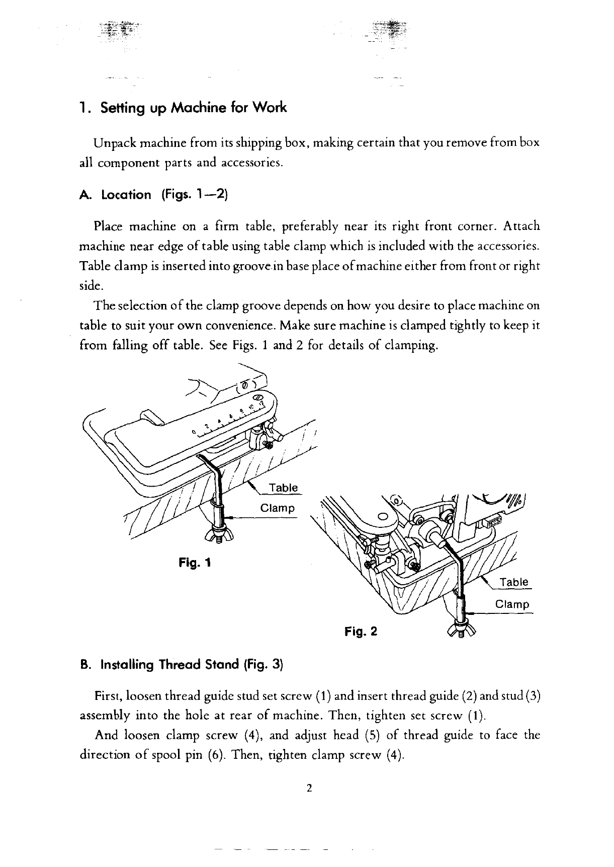
Place machine on a firm table, preferably near its right front corner. Attach
machine near edge
of
table using table clamp which
is
included with the accessories.
Table clamp
is
inserted into groove in base place
of
machine either from front or right
side.
The
selection
of
the clamp groove depends on how you desire to place machine on
table
to
suit your
own
convenience. Make sure machine
is
clamped tightly to keep it
from falling
off
table. See
Figs.
1 and 2 for details
of
clamping.
~
/~l~___.)--...
•
'
•
Fig. 1
'
b
Table
Clamp
Fig. 2
B.
Installing Thread
Stand
(Fig.
3)
Clamp
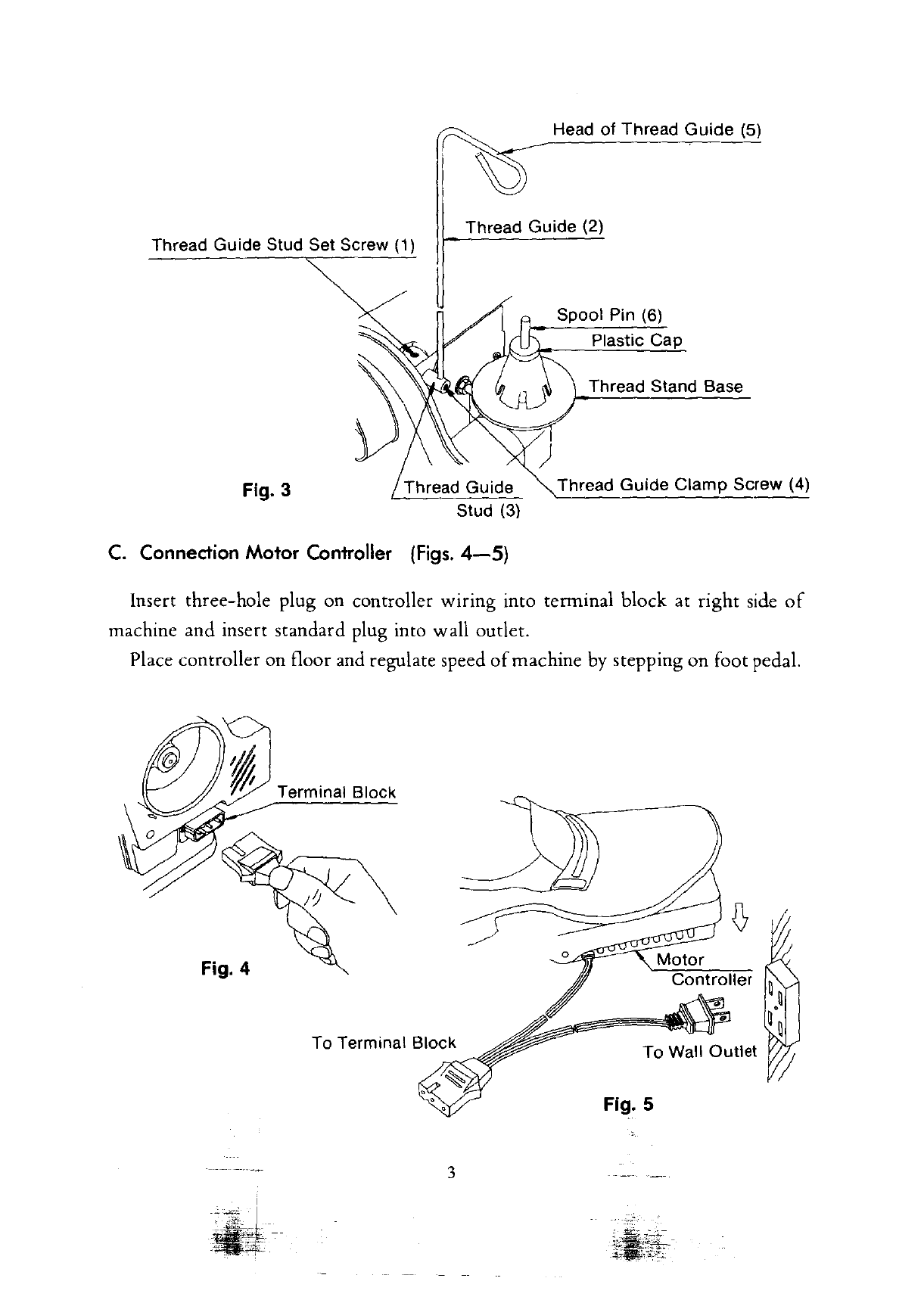
First, loosen thread guide stud set screw (1) and insert thread guide
(2)
and stud
(3)
assembly into the hole at rear
of
machine. Then, tighten set screw
(1).
And loosen clamp screw (4), and adjust head
(5)
of
thread guide to face the
direction
of
spool pin
(6).
Then, tighten clamp screw
(4).
2
From the library of Superior Sewing Machine & Supply LLC - www.supsew.com

Head
of
Thread
Guide
(5)
Thread Guide (2)
Thread Guide Stud Set Screw
(1)
Fig. 3 Thread Guide
Stud (3)
C.
Connection
Motor
Controller
(Figs.
4-5)
Spool Pin (6)
Plastic Cap
Thread Stand Base
Thread
Guide
Clamp
Screw (4)
Insert three-hole plug on controller wiring into terminal block at
right
side
of
machine and insert standard plug into wall outlet.
Place controller
on
floor and regulate speed
of
machine by stepping
on
foot pedal.
Terminal Block
Fig. 4
To
Wall Outlet
Fig. 5
3
From the library of Superior Sewing Machine & Supply LLC - www.supsew.com

D. Assembly of Knee
Lifter
(Fig.
6)
Push
sleeve(!)
onto
free end
of
shaft (2) and allow pin (3) to
enter
L-shaped groove
in sleeve.
In case
of
adjusting the angle
of
knee lifter, loosen the set screw (4) and adjust the
knee lifter to the suitable angle. Then. tighten the set screw (4).
Fig. 6
2.
Lubrication
(Fig.
7)
Set
Screw
(
4)
Pin (3)
\ Knee
Lifter
Shaft
(2)
Knee
Lifter
Sleeve (1)
Lubrication
is
important
for the trouble-free operation and long service life
of
the
machine.
Therefore,
after setting-up machine
as
per
paragraph
1,
drop a sewing
machine oil into all the holes indicated by arrows on Fig. 7, and also drop oil
onto
the
inner
moving
parts
after
opening the side
cover
and rear
cover
of
machine.
Daily and
before
operating
machine, place one
or
two
drops
of
sewing machine
oil into all the oil holes indicated by
arrows
on Fig. 7.
To
assure clean
operation,
it
is
suggested that oiling be done upon completion
of
the
work.
This will
allow
excess oil to drip
off
and only the needed quantity will
remain. Be
certain
to
wipe
off
machine all excess oil before
starting
to
work.
Also
before
sewing,
operate
machine for about a minute
or
so
with
the knee lifter
depressed
to
eliminate
all excess lubricant.
4
From the library of Superior Sewing Machine & Supply LLC - www.supsew.com

Side Cover
3.
Needles
and
Thread
Rear Cover
0
~~LLLJL)z
Fig. 7
The recommended needle
is
system
LW
x
6T
(or style
29-43)
Blindstitch
Machine Needle. Size range from No. 3 to
4.
To assure satisfactory operation needles, thread and fabric must
be
matched
as
suggested in the table below:
NEEDLE
THREAD
MATERIAL
size 3 (11) No.
80-100
Nylon slik and
other
light
weight fabrics
size 3
1/2
(14)
No.
60-70
Cotton,
woolen, and
other
medium
weight fabrics
size 4(16) No.
50-60
Thick woolen and
other
thick
weight fabrics
5
From the library of Superior Sewing Machine & Supply LLC - www.supsew.com

4.
Replacing
the
Needle
(Fig.
8)
Turn
handweel
away
from you (clockwise direction) until needle reaches to the
end
of
its
return
stroke. Remove needle to be replaced by loosening needle clamp
screw
(
1)
about
two
turns.
Insert
new
needle into its seat on needle
carrier
(2)
pushing it
as
far to the left
as
it
will go.
Now,
tighten needle clamp screw
(1).
Note: Fig. 8 shows needle
carrier
and its
part
in a disassembled view.
Fig. 8
Needle Carrier (2)
Needle
Needle
Clamp
Needle
Clamp Screw (
1}
5.
Threading
Machine
(Figs.
9-12)
A.
When
using sewing
thread
from a cone, place it
over
plastic
cup
on thread stand
(Fig. 9)
Thread
Guide
Cone Thread
Needle
Fig. 9
6
From the library of Superior Sewing Machine & Supply LLC - www.supsew.com

B.
When using spool thread, remove plastic
cup before placing spool on thread stand
(Fig. 10).
C. For correct threading
of
machine, follow
carefully course
of
thread
as
shown
on
Fig.
9.
Fig. 10
Spool Thread
Spool
Pin
When
reaching to thread tension device, enter thread first in rear eye
of
thread
guide (1). Then, lead thread between the
two
tension discs (2)
as
per Fig.
9.
Now
enter it from behind through the front eye
of
thread guide. Lead thread
forward
to
front
of
machine. Enter thread from above into thread gruide (3), and eyelet
of
needle clamp (4).
As
this point, make certain that needle
is
in
extreme
left-hand position.
Now
pull
thread through needle eye from below
as
shown in Fig.
11.
It
is
easier
to
pull thread through needle eye when
work
plate
is
opened
by
loosing
the clamp screw (Fig. 12).
Work
Plate
Needle Carrier
Thread
Fig.
11
Fig.
12
7
From the library of Superior Sewing Machine & Supply LLC - www.supsew.com

6.
Inserting
the Work
Piece
and
Starting
to
Sew
(Figs.
13-14)
Depress knee lifter. This causes the cylinder bed
of
the machine to swmg
downward
and creates a gap between the presser foot and the cylinder bed. Insert the
work
in the gap just opened
in
such a manner that the folded
or
sewn edge
of
the
article
is
alongside the edge guide
of
the presser foot.
Edge Guide
Fig. 13
Cloth Retainer
Material
Plunger
Fig. 14-1 Fig. 14-2
When
the article
is
in proper position, completely release the knee lifter.
Get
the
machine started slowly and
watch
the material
pass
edge guide rather than to observe
the action
of
the needle.
In case
of
sewing double folded edge
of
material, insert the material
as
per Fig. 14-
1.
In case
of
sewing single folded, insert the material
as
per Fig. 14-2.
8
From the library of Superior Sewing Machine & Supply LLC - www.supsew.com

7.
Adjustment
of
Thread
Tension
(Figs.
15-16)
Different
kinds and weights
of
material
and
the various sizes
of
thread
require
respective
thread
tensions.
Thread
tension
is
regulated
by
turning
the tension
nut
located
at
the top
of
the machine arm.
Tension Disc
Thread Guide
Tension
Nut
To increase
Fig. 16
Tight
Tension Stitch Loosen Tension Stitch
Fig. 15
To increase
thread
tension, turn the
nut
away
from you (clockwise).
To decrease the tension,
turn
the
nut
towards
you
(counter-clockwise).
Do
not turn, tighten,
or
loosen tension
more
than
about
one
quater
turn
at
one
time.
Test
for results
and
readjust,
if
necessary.
9
From the library of Superior Sewing Machine & Supply LLC - www.supsew.com

8. Regulating
Stitch
Length
(Fig.
17}
Open
side cover by loosing
two
clamp screws. Loosen
two
set screws
(1)
in stitch
regulating collar (2), and
turn
collar (2) until desired number
is
reached by indicator
groove (3)
of
eccentric. Then, tighten screws
(1)
securely.
When
delivered from
our
factory, the
number
for stitch length
of
the machine
is
b
"6"
set
to
e
at
.
Groove
(3)
in Eccentric
Fig. 17
Each
number
shows the following stitch length.
Number
4 5 6 7 8
on
collar
Stitch 4 5 6 7 8
length
(M/M)
To have best choice
of
stitch length, recommend to have a few trial stitching on
different kind materials.
9. Adjustment of Needle Penetration
(Fig.
18)
The
depth
of
needle penetration into the
cloth
can
be
adjusted by turning the
plunger regulator located on front
of
the machine.
For
Thick
Material For
Thin
Material
(0
LESS
t
MORE
..._____:___./
#
'-
Fig. 18
From the library of Superior Sewing Machine & Supply LLC - www.supsew.com

To
increase needle penetration for light materials,
turn
the regulator
counter-
clockwise.
The
greater the number directly in front
on
the regulator dial, the deeper
the penetration
of
the needle. To lessen the penetration for thick materials,
turn
regulator clockwise.
To prevent damage to the needle and
the
machine, it
is
recommended to
begin
sewing
with
the least degree
of
penetration, and to sew a short length
of
seam.
Check
for catching
of
the material and apprearance, making
whatever
penetration
adjustments are required until stitching
is
as
desired.
NOTE:
Beginning and end
of
penetration adjustments are controlled by built-in
stops.
Do
not
force beyond its stops.
10.
Removal
of
the Work
from
the Machine
(Fig.
19)
Stop machine and turn handwheel away from you until needle
is
completely
out
of
the material (at highest position). Press knee lifter to the right and pull
the
work
piece
rearward
out
of
the machine
with
a quick stroke. This
will
lock the last stitch
and
break
the thread.
Highest
Position of Needle
Material
Knee
Lifter
~
....,
...
Fig.
19
---~r
-
-·
~-~-
From the library of Superior Sewing Machine & Supply LLC - www.supsew.com

11.
Skip
Stitch
Device
(Figs.
20-21)
The position
of
the lever at the right side
of
the machine controls the skipstitch
device.
When
this lever points towards
"No
skip", the needle catches the material at
every
stitch.
Pointing
towards "skip", the needle penetrates the material at every
other
stitch.
To
be assured
that
the machine works
as
desired, the lever should be pushed
in
either
direction
until stopped.
If
the lever
is
maintained at intermediate positions,
operation
of
the machine
is
not
reliable. Also note that every time operation
is
changed
from
skip
to
non-skip, needle penetration should be checked and readjusted,
if
necessary.
Skip
Lever
Fig. 20
NO
SKIP
STITCH
SKIP
STITCH
Thread
Material
'<;,,.,.
•t
,(
;r,,.,
-·
Material
Fig.
21
12
From the library of Superior Sewing Machine & Supply LLC - www.supsew.com

PARTS LIST
"%'~
-
;.,..--c
-,,i·-~.-:_-
-
-
---
- -
From the library of Superior Sewing Machine & Supply LLC - www.supsew.com

26
23 24
3
20
10
32
29
(J
~,,
~8
~
7
(I
35
0
19
16
~
fl
~8
17
6
38
5
'
37
" ">
43
·t~
~
..
'I.
~
•
~~
54
1
~
12 55
13
~
~
~
57
"''"
14
8
From the library of Superior Sewing Machine & Supply LLC - www.supsew.com

Ref. Nos.
Parts
No. Description
I 21001
Machine
Frame
2 21002 Cylinder Bed
3 21003 Arm Side Cover
4 21004 Arm Side Cover
Oamp
Screw
5 21005 Pulley Cover
6 0144016 Pulley Cover
Set
Screw
7 21006 Arm Rear Cover
8
0144008
Arm
Rear
Cover
Set
Screw
9 21007 End Cover
10
0174008
End
Cover Set Screw
II
S-21008-G
Machine Base with Rubber Cushion (Moss-Green)
II
S-21008-R
Machine Base
with
Rubber Cushion (Wine-Red)
12 21009 Rubber Cushion (A)
13
21010 Rubber Cushion (B)
14 0186016 Machine Base Clamp Screw
IS
10109-A
Motor
16
B-005
Motor Bracket Set Screw
17 B--006 Motor Bracket Spring Washer
18
B-007
Motor Bracket Spring Washer
19
21
IOI Motor Belt
20 10131 Needle System Label (LW x
6T)
21
4135
Thread Guide (Pig Tail)
22
0144008
Thread Guide
Set
Screw
23
S-21095
Thread Tension Assembly (Ref. Nos. 24-29)
24 21095 Thread Tension Bracket
25 21096 Thread Tension Post
26
4070
Thread Tension Post
Nut
27
5190-A
Thread Tension Disc
28
79-B
Thread Tension Spring
29 83
Thread
Tension
Nut
30
0144008
Thread Tension Bracket Set Screw
31
0046006
Thread Guide Stud Set Screw
32
21093 Thread Stand
33
21094 Thread
Stand
Base
34
AC-IOI
Plastic Cap
35 11145 Thread
Stand
Nut
36 10543 Thread
Stand
Washer
37
S-10513-G
Disc Regulator (Moss-Green)
37
S-10513-R
Disc Regulator (Wine-Red)
38
6074
Disc Regulator Set Screw
39
10514
Disc Regulating Dial Screw
40
10516 Disc Regulating Dial Screw Prop
41
10515-A
Disc
Regulating
Plate
Spring
42
8339
Disc
Regulating Plate Spring Set Screw
43
21068
Disc
Regulator Indicating Label
44
21037 Skip
Stitch
Label
45
10076-A
Cy
tinder Bed Connecting Hook
46
21085 Cylinder Bed Connecting Hook Screw
47 21083 Knee Lifter Crank
48
0216016 Knee Lifter
Crank
Set Screw
49 21084 Knee Lifter
Shaft
so
10074 Knee Lifter
Shaft
Spring Pin
SI
21082
Work Plate Bracket
52
0216016
Work Plate Bracket
Set
Screw
53
21081 Work Plate
54 10085 Work Plate Wing Screw
55 10082 Work Plate
Shaft
56
0216012
Work Plate Shaft Set Screw
57 21023 Work Plate Shaft Collar
58
0096006
Work Plate Shaft Collar Set Screw
59 10083 Work Plate
Screwt,_d
Cap
·.
--·
:-~--:~~-
2
~::~t-
From the library of Superior Sewing Machine & Supply LLC - www.supsew.com

12 13
11
~
2
7~
8
21,,
~
20~
19
50
~53
9
54
~
43
49
2 24
3938
~~
~,
41
37
29 28
27
~
q,-30
3
15
9
~
D
0
17~
10
.~c/xC
18
From the library of Superior Sewing Machine & Supply LLC - www.supsew.com

Ref.
Nos.
Parts
No.
Description
I 21012 Main Shaft
2 21013 Main Shaft Bushing
(Front)
3 0096010 Main Shaft Bushing Set Screw
4
21014
Mairt
Shaft Bushing (Rear)
5 0096010
Main
Shaft Bushing
Set
Screw
6 21015 Main Shaft Thrust Washer
7 21016 Main Shaft Collar
8 0096006 Main Shaft Collar Set Screw
9
21017-G
Pulley (Moss-Green)
9
21017-R
Pulley (Wine-Red)
10
0096014
Pulley Set Screw
11
21018 Eccentric Bushing
12 0096008 Eccentric Bushing Set Screw
13 21019
Main
Shaft Gear (Small)
14 0096006 Main Shaft Gear Set Screw
15
21020
Skip Stitch Gear (Large)
16
21021 Skip Stitch Gear Eccentric Shaft
17
0096010
Skip Stitch Gear Eccentric Shaft Set Screw
18
21015 Skip Stitch Gear Eccentric Shaft Thrust w·asher
19 21022 Skip Stitch Gear Eccentric Shaft
Fork
20 21023 Skip Stitch Gear Eccentric Shaft Collar
21
0096006 Skip Stitch Gear Eccentric
Shaft
Collar Set Screw
22 21024 Connecting Link {Long)
23 21025 Connecting Link/Rod Holding Screw
24 10060 Connecting Link/Rod Holding Screw Snap Rirtg
25 10627 Connecting
Link/Rod
Holding Screw Spring Washer
26 17202 Connecting Link/Rod Holding Screw
Nut
27 21026 Connecting
Rod
28
21027 Skip Stitch Eccentric Shaft
29
21023 Skip Stitch Eccentric Shaft Collar
30
0096006 Skip Stitch Eccentric Shaft Collar Set Screw
31
21028 Skip Stitch Lever Plate
32
0124008 Skip Stitch Lever Plate Set Screw
33
4010
Skip Stitch Lever Plate Ball
34
10052 Skip Stitch Lever Plate Spring
35
S-21029
Skip
Stitch
Lever
36 0096010 Skip Stitch Lever Set Screw
37
21031 Connecting Link {Short)
38
21032 Connecting Link Holding Pin
39
10060 Connecting Link Holding Pin Snap Ring
40
0094004 Connecting Link Holding Pin
Set
Screw
41
21033 Connecting Block
42
0214012 Connecting Block Set Screw
43
S-21034
Ridge Formirtg Disc Shaft Assembly
44
21036
Ridge Forming Disc Shaft Collar
45
0094004
Ridge Forming Disc Shaft Collar Set Screw
46
10517 Ridge Forming Disc Shaft Bushing
47
0094006 Ridge Forming
Disc
Shaft
Bushing Set Screw
48
21069 Cylinder Bed Shaft
49
0096006
Cylinder Bed Shaft Set Screw
so
19117 Cylinder Bed Shaft Snap Ring
SI
21070
Cylinder
Bed
Shaft Spring
52
21071-A
Cylinder Bed Shaft Spring Pin
53
21016
Cylinder Bed Shaft Collar
54
0096006
Cylinder Bed Shaft Collar
Set
Screw
4
From the library of Superior Sewing Machine & Supply LLC - www.supsew.com

33
34
~
35
47
46
49"1
J21
(JJ-19
~52
~20
{j--70
48
~--69
52
/66
tr
,67
68 65
~
60
~~
59~
_/_
,~
58~
~
\
62~
57~
~
vi)
'63
64
'""~
61
~
74~
I
◄
1
78
~~
~
79~
72
75
80
76
-::::.-=~
71
'
78
81
77
5
From the library of Superior Sewing Machine & Supply LLC - www.supsew.com
Table of contents