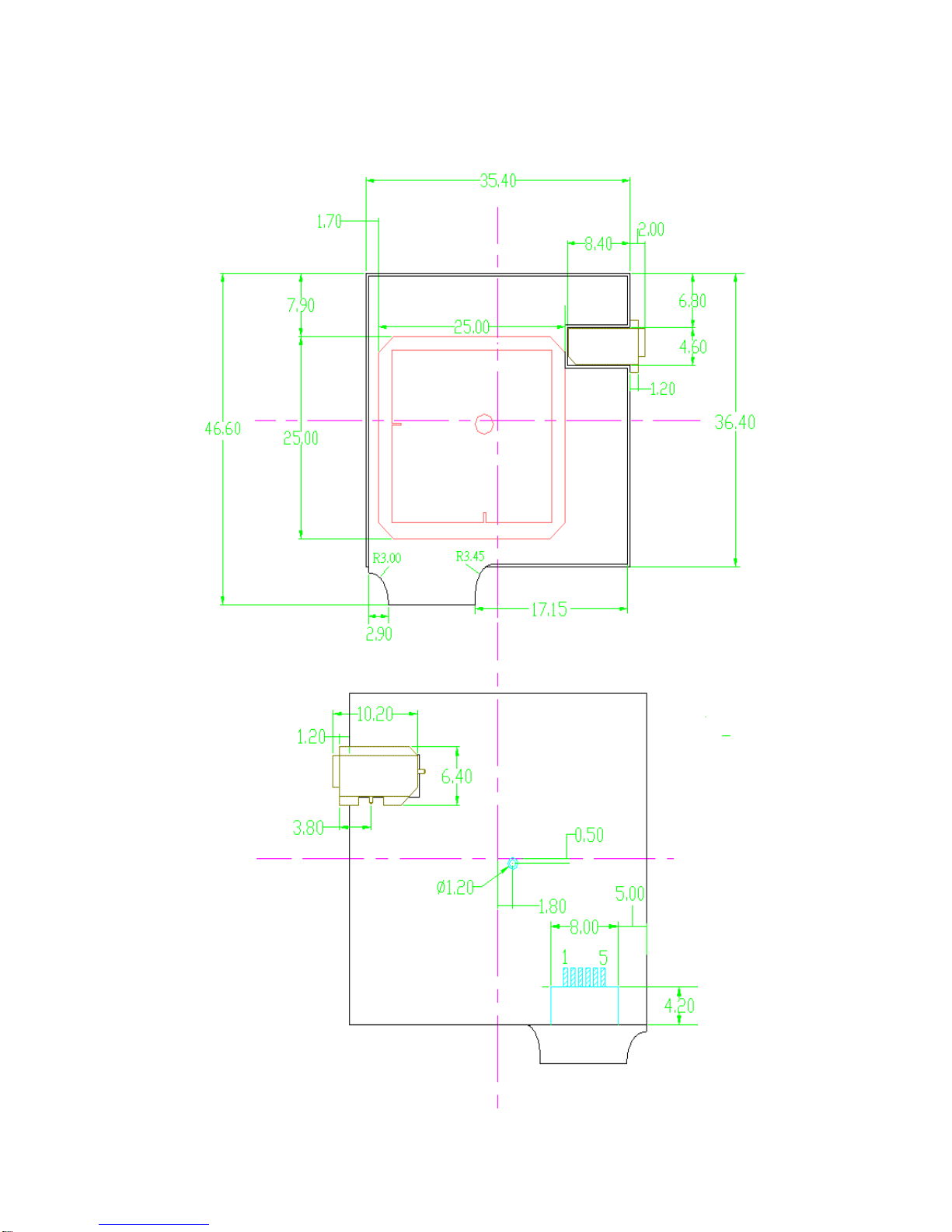
Global Sat EM-408 User manual
Other Global Sat GPS manuals

Global Sat
Global Sat TR-102 User manual

Global Sat
Global Sat DG-200 User manual

Global Sat
Global Sat GH-615B User manual

Global Sat
Global Sat GS-3212 User manual

Global Sat
Global Sat EM-318-02 User manual

Global Sat
Global Sat ET-212 User manual

Global Sat
Global Sat TR-151A User manual

Global Sat
Global Sat LT-10 Series User manual

Global Sat
Global Sat GB-580 User manual

Global Sat
Global Sat TR-313 User manual

Global Sat
Global Sat BR-355 Operational manual

Global Sat
Global Sat BU-353N5 User manual

Global Sat
Global Sat GPS Director YE-GD101 User manual

Global Sat
Global Sat MR-350N User manual

Global Sat
Global Sat BT-338 User manual

Global Sat
Global Sat BU-353 User manual

Global Sat
Global Sat BT-368i User manual

Global Sat
Global Sat Globalsat BT-359 User manual

Global Sat
Global Sat GD-101 User manual

Global Sat
Global Sat BR-355 User manual