Global Flogos Lite User manual

instruction manual
by global special effects
www.globalspecialeffects.com
Version 1.2 Update 08.05.2011
©2011 Global Special Effects, Inc.


11054 COUNTY ROAD 71
LEXINGTON, AL 35648
www.GLOBALSPECIALEFFECTS.com
Sales: 256-229-5551
Fax: 256-229-5552
Tech Support
256-229-5551
Limited Lifetime Warranty
Global Special Effects™ provides a limited lifetime warranty for the Flogo-lite from any manufacturing
defects. Any misuse, abuse, or negligence automatically voids our warranty. Running any other
liquids/materials other than the Global Special Effects™’ solutions through the pump automatically
voids our warranty. Global Special Effects™ is not responsible for loss of income, labor, or business
as a result of a Flogo-lite’s malfunction. Global Special Effects™ is not responsible for physical
damage, scratching or tube damage after shipping from Global Special Effects™’ Manufacturing
facility. For safety reasons, Global Special Effects™ will repair damaged electrical wires per the
warranty. There is a lifetime warranty on the circuit board and other electronics to the fan or pump.
Direct all questions and claims to the Global Special Effects™ customer service at 256-229-5551
from 8-5 Central time or the 24 hr live tech support line at 256-366-6163.

Flogos-lite™
Flogos-lite™ Instruction Manual
Positioning your Flogos-lite Machine
Opening your Flogos-lite Machine
Position the Flogos-lite in the desired place for
the event. Although the Flogos-lite will still
need to be manually leveled, it is to your
advantage to begin with a place as level as
possible.
Unlatch the 4 latches which secure the top of the case.
Remove the top and set aside noticing that the Skirt and
Windscreen are secured to the lower side of the Case Top.
1
©2011 Global Special Effects, Inc.

Flogos-lite™ Instruction Manual
Flogos-lite™
Ling the Inner Top
Each of the two persons should be standing on the sides of the Flogos-lite machine where the
oval shaped hand holds are located on the Inner Top. Each person should grasp the Inner Top by
placing their hand through the oval shaped hole. Lift the Inner Top keeping it relatively level as
it is being lifted.
Each person then unfolds one of the legs by depressing the
leg locking button located in the gap near the hinge point
of the leg. The leg is folded downward until it locks into
position with an audible “click.” Each person then holds
the Inner Top with the opposite hand and repeats the leg
unfolding with the remaining leg making sure there is an
audible “click” indicating the leg is locked into position.
Unfolding the Legs
2

Flogos-lite™
Flogos-lite™ Instruction Manual
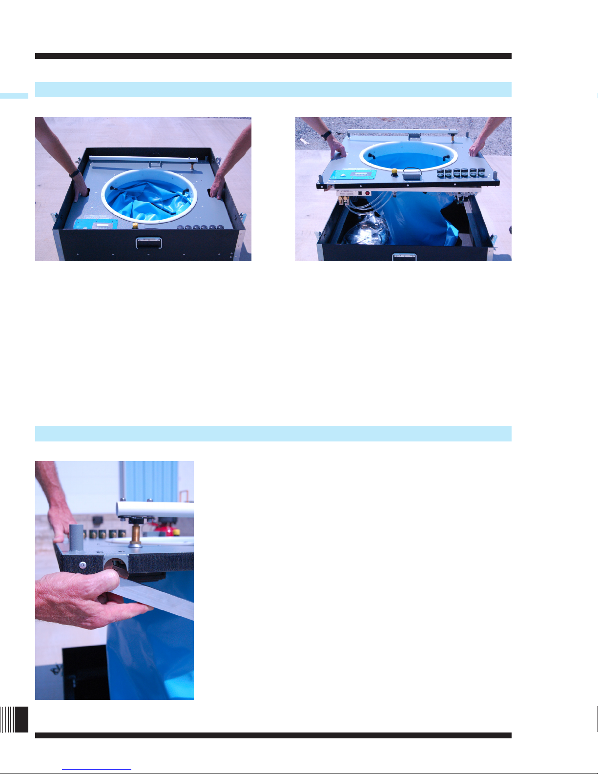
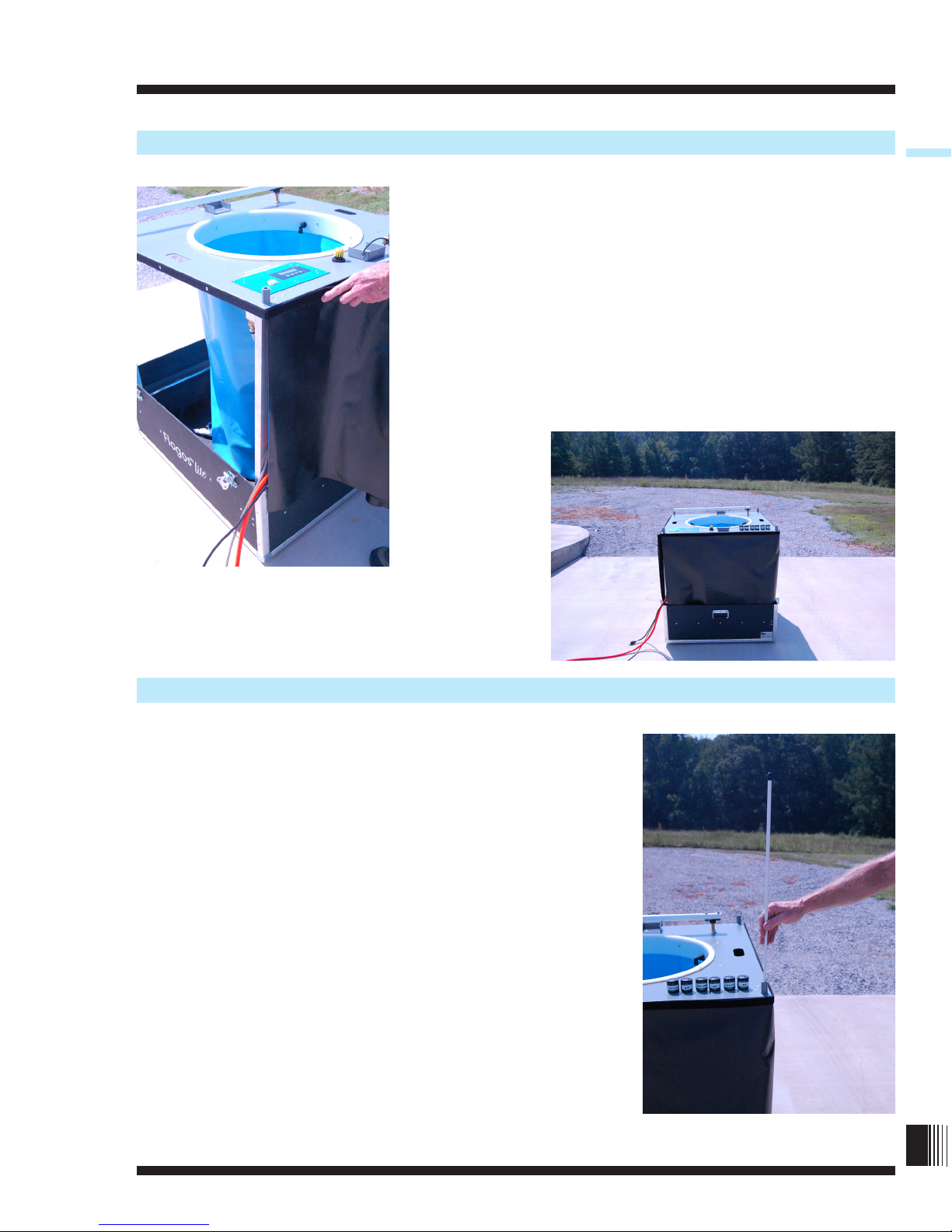
Set Legs Into the Leg Locks
Lower the Inner Top until the legs rest on the Leg Locks located in each of the four corners of the
Lower Case. Guide each leg into the square hole in its Leg Lock. There are no locking mechanisms
to hold the legs into the Leg Locks. Each leg, though, must rest in the bottom of its’ repective Leg
Lock in order for the Inner Top to be properly leveled and for proper operation of the Flogos-lite.
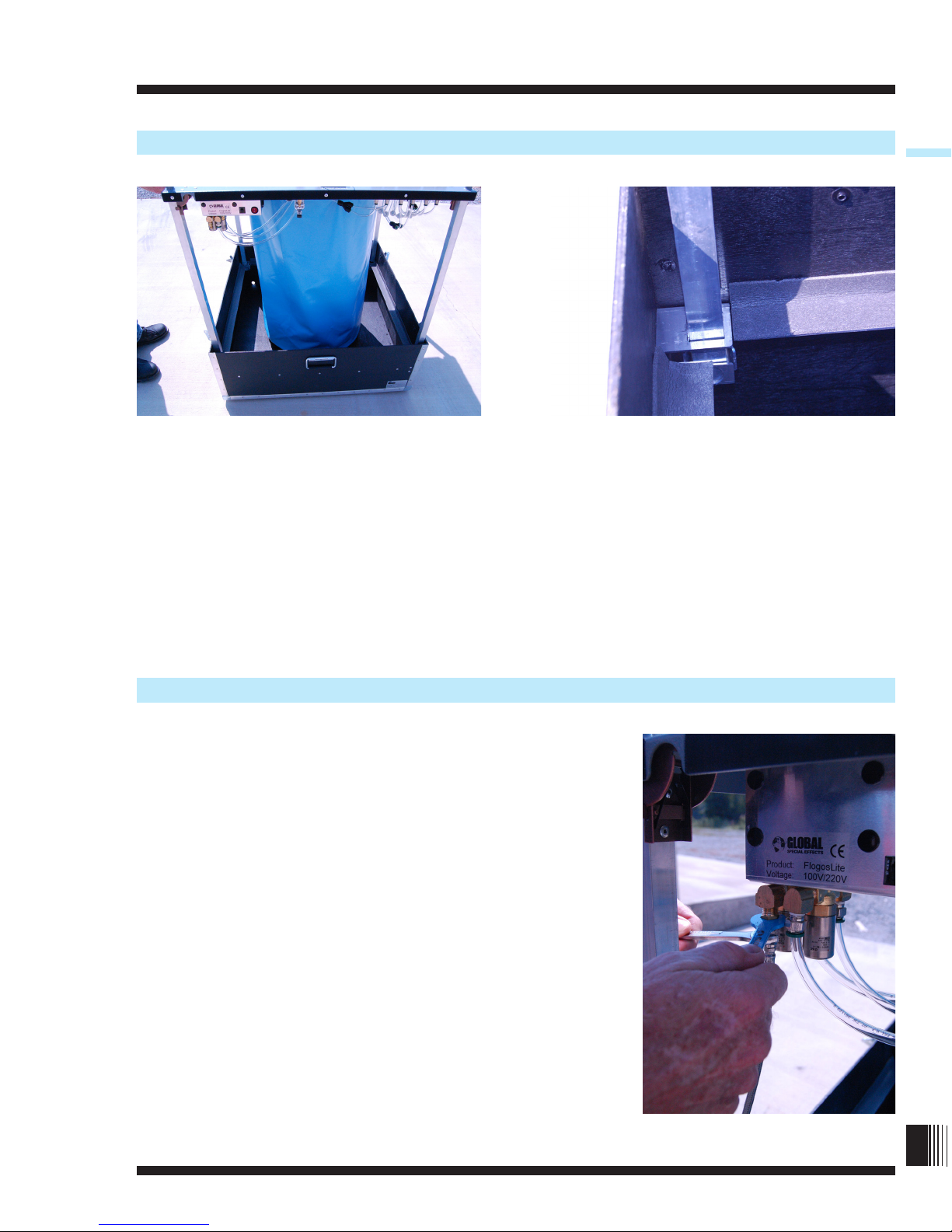
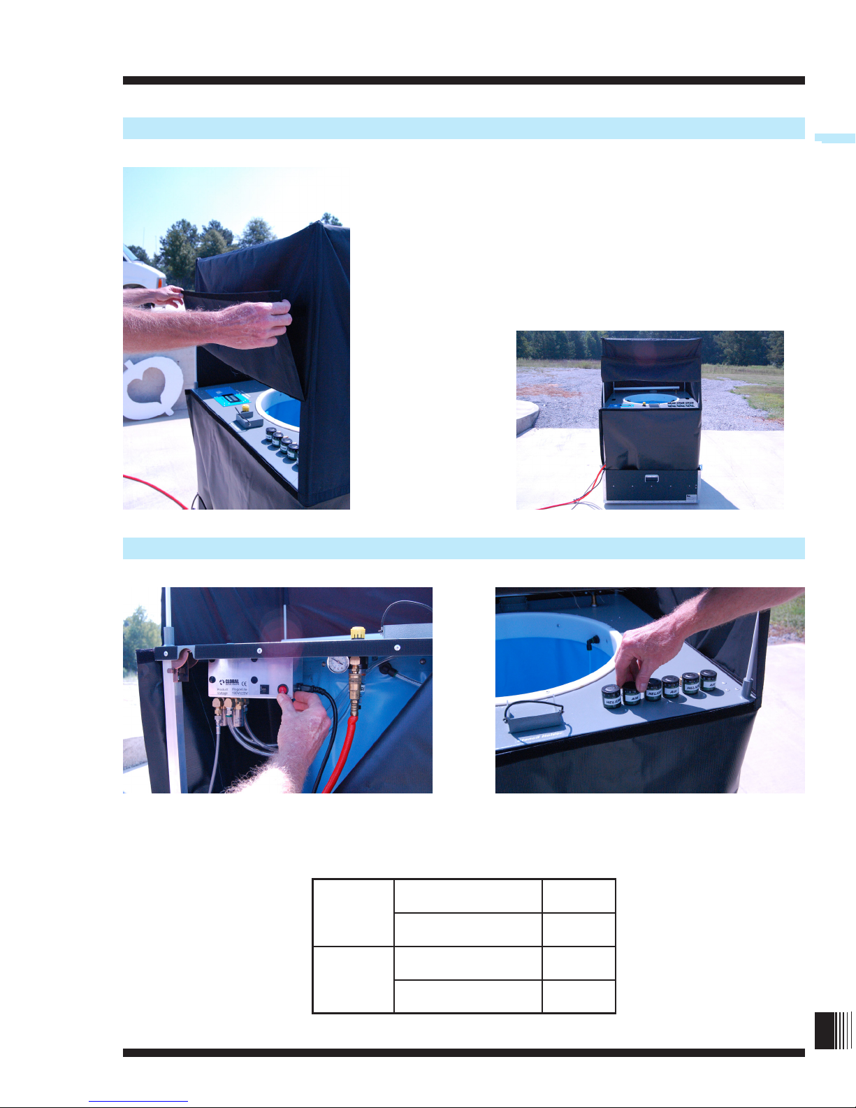
Attach the helium hose to the tting on the gas control
solenoid located on the lower side of the Controller
Enclosure. Using two 9/16” open end wrenches (included)
hold the tting on the solenoid valve with one and tighten
the gas hose tting with the other. This prevents undue
stress being placed on the solenoid valve which could dam-
age it.
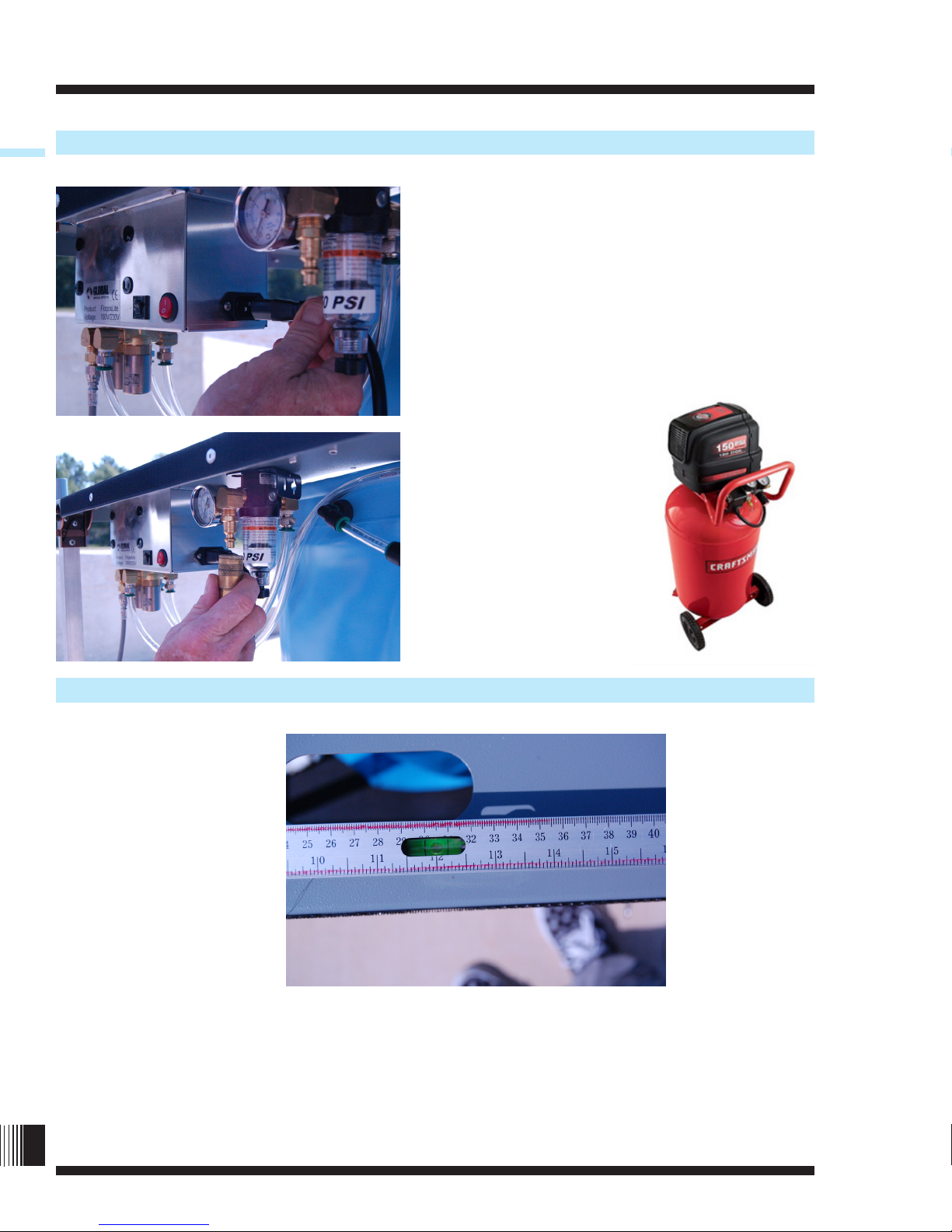
The supplied regulator is a U.S. standard CGA-580 inert gas
tting. If the supplied regulator cannont be used, and a
different regulator is used, make sure it is capable of a
steady 50 PSI output.
Do not adjust tting.
Attaching the Helium Hose
3
©2011 Global Special Effects, Inc.

Flogos-lite™ Instruction Manual
Flogos-lite™
Insert the female end of the power cord into the
receptacle in the end of the lower right side of the
Controller Enclosure. Attach the female quick
coupling of the air hose to the male air tting on
the air lter regulator.
Global Special Effects technicians use a 33-Gal-
lon 1.6-hp Craftsman air compressor capable of
approximately 5.5 SCFM (155.76 Liter/Min) ow
rate at 70 PSA (4.82 Bar).
Use a carpenter’s level to adjust the Flogos-lite
as level as possible in both horizontal
directions.
Attaching the Power Cord and Air Hose
Levelling your Flogos-iite
4

Flogos-lite™
Flogos-lite™ Instruction Manual
Remove the Skirt from the lower side of the Case Top. The
Skirt is attached by pressing the hook and loop fastener
attached to the Skirt to the hooks which are attached
around the outer perimeter of the Inner Top beginning on
the left hand side of the rear of the Inner Top. Continue
attaching the Skirt around the Inner Top tucking the lower
edge of the Skirt into the Lower Case as you proceed. The
small gap left at the junction of the ends of the Skirt is
where the hoses and power cord pass through.
Remove the Windscreen from the Case Top where the Skirt
was stored. Begin installing the Windscreen by inserting the
upright supports, which have black caps, into the
Windscreen support sockets.
Attaching the Skirt
Attaching the Windscreen
5
©2011 Global Special Effects, Inc.

Flogos-lite™ Instruction Manual
Flogos-lite™
At the inside of each of the four corners of the
Windscreen, you will nd a sewn “pocket.” While draping
the Windscreen over the Flogos-lite, place each rod into
one of these pockets.
Pull the bottom edge of the Windscreen down and press
the hook and loop fastener onto the loops on the top edge
of the Skirt.
Attaching the Windscreen
6

Flogos-lite™
Flogos-lite™ Instruction Manual
There is an opening at the rear of the Windscreen which
should be oriented to the rear of the Flogos-lite in order to
gain access to the controls. The ap covering the controls
can be unzipped, raised upward, and secured by the small
tabs of hook and look fasteners located above the ap.
Access to the controls is then possible. During opperation
of the Flogos-lite, this ap should be lowered and secured
by the hook and loop fasteners along its’ lower edge.
With power switch OFF, adjust the air and helium valves as required.
The Windscreen Opening
Adjusting the Air and Helium
7
©2011 Global Special Effects, Inc.
24”
Helium 2
Air 6
36”
Helium 2
Air 15

Flogos-lite™ Instruction Manual
Flogos-lite™
Make sure the air regulator is at 50 PSI.Adjust the air
regulator as required.
Fill the Flogos-lite with the correct amount of de-ionized water so that the water level is 1.5 - 2
inches avove the top of the bubbler heads. The ll height bobber indicator should ip over at
correct ll height.
Adjusting the Air Regulator
Filling Water
8

Flogos-lite™
Flogos-lite™ Instruction Manual
Adding Flogo Juice
Mixture Quantities
24” 9 gal 42 oz
36” 25 gal 1 gal
In a seperate container, prepare the mixture of de-ionized water and Flogo Juice, 25:1. See
the chart above to review approximate mixture quantities for each machine.
Priming the Flogo-lite
After adding the Flogo Juice to your tank, wait approximately 7 minutes for the Flogo-light
to prime or until foam beings to rise slightly above the Inner Top. Place the stencil into place
and begin your cycle. After innitial swipe, the Flogo-lite is fully primed and ready to run the
desired cycle.
9

Flogos-lite™ Instruction Manual
Flogos-lite™
Draining the Flogo-lite
10
At the end of the event, shut down the machine:
• Turn the power switch off
• Close the helium valve
• Turn off the air source
• Disconnect the helium and air
• Unplug the power chord
The Flogo-lite machine must be drained before breaking down and boxing up.
Additional Instructions
To change the Flogo thickness
•Presstheredstopbutton.
•Changethetimeasdirectedabove.
•(Asapossiblealternative,youmaywanttoadjusttheheliumandairsettings).
•Pressthegreenstartbutton.
To change the stencil
•Presstheredstopbutton.
•Turntheredgasswitchoff(O).
•Removetheoldstencil,replacewithnewoneandsecure.
•Turntheredgasswitchon(|).
•Pressthegreenstartbutton.
Adding uid
If desired, additional premix of Flogo uid and water may be added at anytime to the rell
reservoir at the lower right.

Flogos-lite™
Flogos-lite™ Instruction Manual
Adding Color
1. Prepare the Flogo Juice mixture
2. Measure out 2 1/2 percent Flogos Juice Color Concentrate to the volume of Flogo Juice
mixture used:
Ex: 3.2 ounces of Flogo Juice Color Concentrate per 1 gallon of Flogo Juice mixture. (25 ml of
Flogos Juice Color Concentrate per 1 liter of Flogo Juice mixture).
Flogo Machine Tank Reservoir Color Concentrate to be Added
24” 8 gal 50-100 ml
36” 25 gal 125-175 ml
3. Before the machine is turned on and the foam begins to form, pour the Color Concentrate
into the uid reservoir tank. Be careful to pour slowly, and avoid splashing concentrate onto
the walls of the tank.
4. The Color Concentrate can be modied to deepen or lighten the
color. The concentrate can be adjusted by either increasing or decreas-
ing the liquid color concentrate by increments of 1 percent. Please
contact tech support for further questions.
5. Flogo Juice Color Concentrate is 100% safe and environmentally
friendly. It is made from the same active ingredients used in children's
washable paints. Colored Flogo Juice mixture will temporarily stain
skin and clothing, but washes out with soap and warm water. Care
should be exercised not to spill excess colored Flogos mixture onto the
concrete.
6. To fully remove the color from the reservoir tank, drain the uid and spray the inside of the
tank with water,and continue to drain the uid. Repeat as necessary.
11


Flogos-lite™
Flogos-lite™ Instruction Manual
Place your blank stencil on a wall.
Find the center of the stencil and mark it.
Using your guide wire, trace your circle.
Project your image onto the stencil, making sure it ts
inside your circle.
Stencil Cutting
13

Flogos-lite™ Instruction Manual
Flogos-lite™
Cut out your stencil using a
hot knife or electric knife.
Remove the negative from
the stencil. Always save your
negative for creating new
stencils.
Trace your image, making sure to exaggerate some lines so
that your Flogo is created properly.
You may need to attached
wire mesh so that your Flogo
comes out evenly.
Stencil Cutting
14


Flogos-lite™ Instruction Manual
Flogos-lite™
After the Set-Up steps have been completed, the Flogos-lite can be operated in either of the two
modes: “Manual Override” or “Event Timer.” Although there are similarities between the two
modes of operation, each mode will be addressed seperately as there are a few differences in the
programming of the controller.
Press the rocker switch to turn the controller on. The switch is located on the front of the
controller enclosure below the rear of the inner top. When the controller is powered the “Power”
light on the face of the controller will illuminate. The screen of the controller will also illuminate
but will dim after approximately three and a half minutes if now buttons on the
controller are pressed. The controller is still powered if the “Power” indicator is illuminated. The
screen will illuminate again when any buttons are pressed.
After power is applied and before any buttons are pressed, the screen will scroll indicating the
states of the controller.
Operation
Manual Override Mode
To begin Manual Override Mode, press “Enter” once. The screen will then read, “Manual Over-
ride Priming, Press Enter.” The helium and aire solenoids are now open and there should be an
audible indication of bubbling in the tank. When in Manual Override mode there is no automatic
transition to the Running Cycle. The Priming Cycle should be allowed to continue for
approximately 7 minutes or until foam begins to slightly lift your stencil. Be certain that the tabs
on the opposite sides of the stencil are located in the stecil holders.
Press “Enter” once and the Running Cycle begins. The screen should now read, “Manual
Override Running, wait___s,” specifying the nuber of seconds for the cycle, or cutting time. To
change the cycle time press either the “Up” or “Down” arrow buttons to choose the time
ranging from 5 seconds to 180 seconds. The “Manual/Enter” button must be pressed once to
initiate the time change which will take effect after the current cycle completes.
To end the Manual Override cycle, press “Menu.” The screen will now read “Status Idle” and will
scroll through the different functions. During “Status Idle,” the helium and aire solenoids will
close and there should be no audible indication of bubbling in the tank.
9
©2011 Global Special Effects, Inc.
16

Flogos-lite™
Flogos-lite™ Instruction Manual
Event Timer Mode
To set the Event Timer Mode, press “Menu.” The screen will now read, “Time Events.” Press
“Manual/Enter” once. The screen should now display, “Timer Event:1.” “Event:2” can be
selected using the “Up” or “Down” arrow buttons. As both Event Timers are set by the same
method only one will be covered here.
When the desired Event Timer is displayed, press “Manual/Enter” once. The start (“On”) and
stope (“Off”) times for the event are displayed and the hour setting for the start time should
be blinking. Using the “Up” or “Down” arrow buttons, select the hour for the event start time.
AM or PM can be selected. To choose the hour setting, press “Manual/Enter.” The hour setting
is thus entered into the memory and the minutes for the start time are now blinking. Using the
“Up” or “Down” arrow buttons, choose the start time in minutes. Press “Manual/Enter” once.
THe start time minutes are entered into the memorey and the hours for the stop time are now
blinking. The hours and minutes for the stop time is chosen exactly linke the start time. When the
correct stop time is chosen press “Manual/Enter” once. The screen now displays the On days and
Off days for the event and Sunday is blinking. All the days of the week are set to Off by default.
To choose which days are timer controlled (On) use the “Up” or “Down” arrow buttons to move
the desired day to the “On” position. To lock a day in the “On” position, or to select a
different day, press “Manual/Enter.” After all the days have been selected or scrolled through,
press “Manual/Enter.” The screen will display the start and stop time and the days selected.
If changes need to be made, press “Manual/Enter” and Edit and Deleter are displayed on the
screen. With the arrow beside Edit, press “Manual/Enter” and the process of setting the On and
Off hours, minutes, and seconds begins again witht eh On hours blinking. Scroll through when
no changes are desired by pressing the “Manual/Enter” button. The On and Off days are dis-
played and if no cahnges are required, scroll through by pressing the “Manual/Enter” button un-
til the screen, once again, displays “Edit Delete.” If all hour, minutes, and days are correct, press
the “Menu” button and those settings for that event are recorded in the memory. The second
Event TImer is set using the same method.
10 17
Table of contents
Other Global Dj Equipment manuals