DIRECTIVES DE CONFIGURATION / CONNEXION
Installez la Sat-Fi2 Remote Antenna Station (RAS)
conformément au Guide d’installation rapide du Sat-Fi2
Remote Antenna Station et exécutez les étapes suivantes:
• Mise sous tension du RAS - La séquence de mise
sous tension peut durer jusqu’à 5 minutes.
• Lorsque les voyants d’alimentation et satellite DEL
clignotent simultanément, passez à l’étape 2.
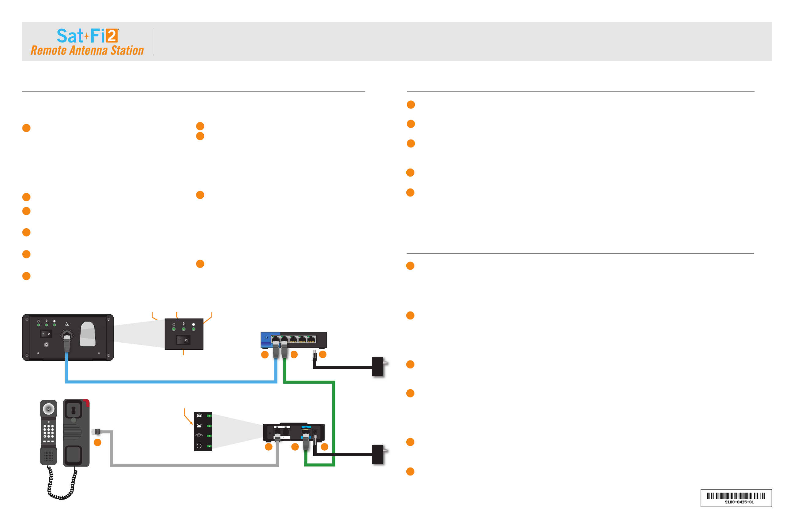
Connectez un câble éthernet au port éthernet RAS.
Connectez l’autre extrémité du câble éthernet au port
1 du commutateur à 5 ports.
Connectez un câble éthernet au port 2 du commutateur
à 5 ports.
Connectez l’autre extrémité du câble éthernet au port
Internet du routeur VoIP Cisco.
Connectez un câble RJ11 au port Phone 1 du routeur
VoIP Cisco.
Connectez l’autre extrémité du câble RJ11 au téléphone POTS.
Pour le commutateur à 5 ports, exécutez les étapes suivantes:
• Connectez le câble d’alimentation dans le port
d’alimentation du commutateur à 5 ports.
• Connectez le câble d’alimentation à une source de
courant CA. Attendez 30 secondes pour la mise sous
tension et la connectivité éthernet.
Pour le router VoIP Cisco, exécutez les étapes suivantes:
• Connectez le câble d’alimentation dans le port
d’alimentation du router VoIP Cisco.
• Connectez le câble d’alimentation à une source de
courant CA.
• La durée de démarrage peut prendre jusqu’à 2
minutes.
Lorsque le voyant DEL téléphone 1 du router VoIP Cisco
passe au vert continu, le téléphone POTS est fonctionnel.
NOTE: Les étapes suivantes doivent être exécutées dans le bon ordre. NE METTEZ aucun appareil sous tension avant
d’avoir reçu la directive de le faire dans les étapes ci-dessous.
1
2
3
4
5
6
7
8
9
10
PLACER UN APPEL EN UTILISANT LE TÉLÉPHONE DE SERVICE TÉLÉPHONE DE BASE
DÉPANNAGE
Assurez-vous que le voyant d’alimentation DEL du Sat-Fi2 RAS et le voyant DEL satellite clignotent en vert.
Soulevez le combiné du téléphone POTS et vérifiez s’il y a une tonalité.
Composez le numéro d’un téléphone cellulaire américain ou canadien, en utilisant la numérotation usuelle à 10 chiffres.
Exemple : (555) 543-1234
Il faudra un court moment avant d’entendre une sonnerie et un court délai après que l’appel soit répondu.
Dès que complété, raccrochez et l’appel est terminé.
Remarque : Pour une urgence faites le 911. Cela n’enclenche pas le mode S.O.S. mais appellera directement GEOS au
Centre International de coordination des opérations de sauvetage d’urgence (IERCC).
Sur le Sat-Fi2 RAS, exécutez les étapes suivantes :
• Vérifiez si les voyants DEL d’alimentation et satellite clignotent en vert.
• Si le voyant satellite clignote en rouge, le RAS Sat-Fi2 est en attente de connexion. Le Sat-Fi2 RAS se connectera
automatiquement.
Sur le commutateur à 5 ports, exécutez les étapes suivantes:
• Vérifiez si l’interrupteur d’alimentation est sous tension.
• Vérifiez que les connexions éthernet entre le Sat-Fi2 RAS et le commutateur à 5 ports sont connectées et
sécurisées en conformité avec le schéma.
Vérifiez que les connexions Ethernet entre le commutateur 5 ports et le routeur VoIP Cisco sont connectées de manière
sécurisée conformément au schéma.
Sur le routeur VoIP Cisco, exécutez les étapes suivantes:
• Vérifiez si le voyant DEL du téléphone 1 est au vert.
• Si le voyant DEL du téléphone 1 n’est pas au vert, procédez comme ceci:
¶Débranchez le câble d’alimentation du routeur VoIP Cisco et attendez 30 secondes.
Connectez le câble d’alimentation au routeur VoIP Cisco et attendez que l’appareil redémarre. Cette attente peut durer
jusqu’à 2 minutes.
Le voyant DEL du téléphone 1 doit être au vert et le téléphone POTS du Sat-Fi2 RAS est fonctionnel.
R-1
1
1
2
2
3
3
4
4
5
5
6
34
5
6
8
9
Sat-Fi2 RAS
Téléphone de service téléphonique de base
Voyant DEL du téléphone 1
Voyant DEL
d’alimentation
Voyant DEL
S.O.S.
Voyant DEL
satellite
Interrupteur d’alimentation
Commutateur à 5 ports
Câble d’alimentation
du commutateur à
5 ports
Câble d’alimentation
du routeur
VoIP Cisco
Routeur VoIP Cisco
1
10
7
2
GUIDE D’INSTALLATION DES SERVICES TÉLÉPHONIQUES DE BASE DE VOIX PAR IP (POTS)
12VDC
SOS
RESET PHONE 1 PHONE 2INTERNET DC 5V
POWER
FLASH REDIAL SOS
123
456
789
0#
5-PORT GIGABIT SWTICH
SE3005
LINKSYS
SYSTEM
12345
LINK/ACT/GB
SOS
12VDC
SOS
RESET PHONE 1 PHONE 2INTERNET DC 5V
POWER
FLASH REDIAL SOS
123
456
789
0#
5-PORT GIGABIT SWTICH
SE3005
LINKSYS
SYSTEM
12345
LINK/ACT/GB
SOS


