GlobalTime Electronic GTT-400 User manual

GlobalTime™NTP Server
Table of Content
Chapter 1 Basic Information of the Device
1.1. Features................................................................................................................................................Page 1
1.2. Applications..........................................................................................................................................Page 1
1.3. Network Protocols................................................................................................................................Page 1
1.4. Mechanical/Environmental ..................................................................................................................Page 1
1.5. Packing List...........................................................................................................................................Page 2
1.6. An Overview of the Server....................................................................................................................Page 2
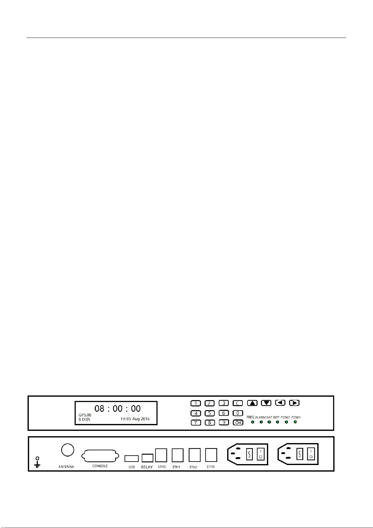
1.7. Front Panel and Rear Panel...................................................................................................................Page 2
Chapter 2 Installation and Commissioning of the Device
2.1. Structure of the Server..........................................................................................................................Page 3
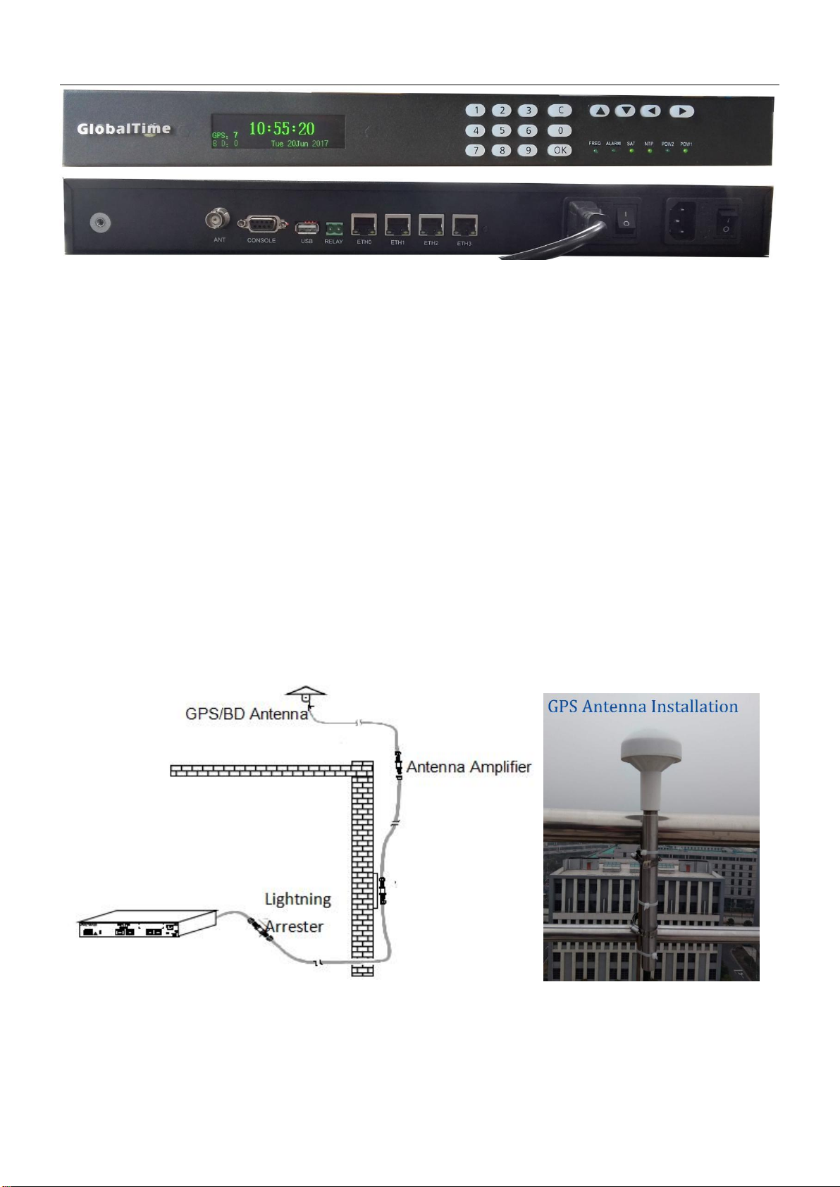
2.2. Outdoor Installation..............................................................................................................................Page 4
2.3. Indoor Installation................................................................................................................................Page 5
Chapter 3 Operation of the Server
3.1. Indicator Light.......................................................................................................................................Page 5
3.2. Keyboard...............................................................................................................................................Page 5
3.3. Configuration of the Server...................................................................................................................Page 7
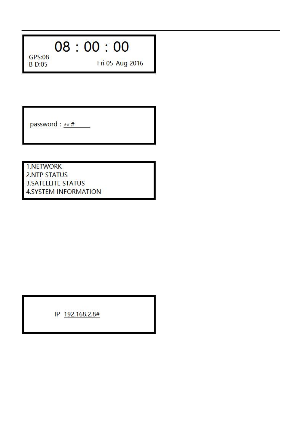
3.3.1. Login..................................................................................................................................................Page 8
3.4. Login Server by Internet........................................................................................................................Page 8
3.5. Remote Dial-up Maintenance...............................................................................................................Page 8
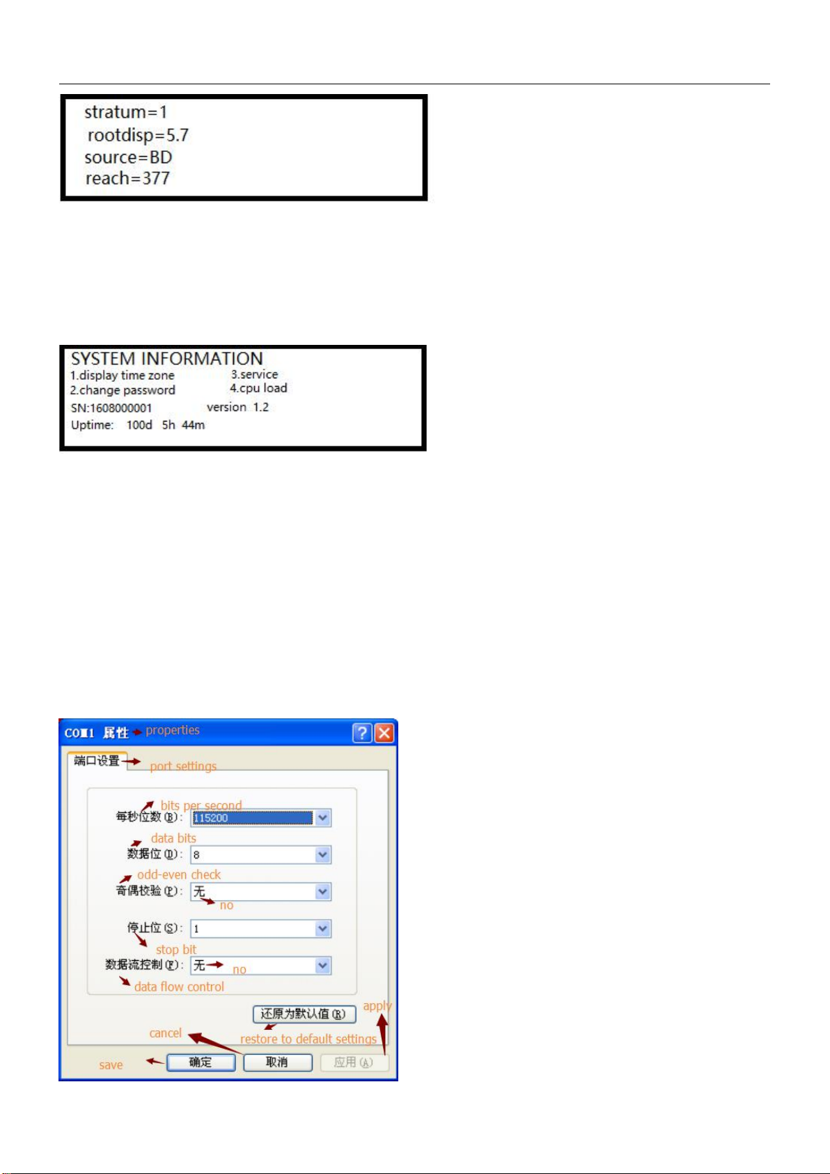
3.6. Configuration of Client Program...........................................................................................................Page 9
3.7. Troubleshooting..................................................................................................................................Page 10
3.7.1. Display Wrong Time When Power is on...........................................................................................Page 10
3.7.2. All indicator Lights are off When Power is on..................................................................................Page 11
3.7.3. Can not Receive Satellite Signal for Long Time................................................................................Page 11
3.7.4. Can not Ping the Server................................................................................................................Page 11
3.7.5. Unstable Signal, and the Server is in hold mode sometimes.......................................................Page 11
3.7.6. Clients can not Get Time Service.................................................................................................Page 11
3.7.7. How to Make Network Devices Get Time Service.......................................................................Page 11
Chapter 4 Remote Login............................................................................................................................Page 12
4.1. Login via http..........................................................................................................................................Page 12
4.2. Login via ssh............................................................................................................................................Page 13
4.2.1. Main Login Interface............................................................................................................................Page 14
4.2.3. NTP Configuration...............................................................................................................................Page 14
4.2.4. NTP Status...........................................................................................................................................Page 14
4.2.5. BD/ GPS Status.....................................................................................................................................Page 15
4.2.6. System Information.............................................................................................................................Page 15
4.2.7 System Function...................................................................................................................................Page 15
Chapter 5 SNMP Monitoring.....................................................................................................................Page 15
5.1. Set SNMP TRAP IP Address.....................................................................................................................Page 15
5.1.1. Set SNMP TRAP IP Address via Web....................................................................................................Page 15
5.1.2. Set SNMP TRAP IP Address via NTPSHELL...........................................................................................Page 16
5.2. Introduction of SNMP OID......................................................................................................................Page 16
5.2.1. TRAP OID16.........................................................................................................................................Page 16
5.2.2. Get OID................................................................................................................................................Page 17

GlobalTime™NTP Server
1
Chapter 6 Specific Performance Index of the Server................................................................................Page 17
Chapter 1 Basic Information of the Device
Modern networks require accurate, secure, and reliable time service. The security-hardened GlobalTime™ NTP
Server is purpose- Built to deliver exact hardware-based Network Time Protocol (NTP) timestamps. The
unparalleled accuracy and security is rounded out with outstanding ease-of- use features for reliable network time
services ready to meet user network and business operation needs today and in the future. High Security and
Capacity.
1.1. Features
• Stratum 1 operation via GPS/BeiDou/GLONASS satellites
• One/ two/ four standard GbE ports, all with patented NTP hardware timestamping
• Security-hardened NTP Reflector™ with firewall protection
• Web-based management with high-security cipher suite
• Exceptional time accuracy to UTC
• Extended environmental specifications
• IPv4 on all ports
• Rubidium atomic clock or OCXO oscillator upgrades
• Single power supply or dual power supply option
• Can be set as a slave time server to synchronize with host time server
• One 10M 100M 1000M adaptive network interface
• NTP Reflector option: 20000 NTP client mode three requests per second
• TOD/1PPS/10MHz out
• MTBF: 90000 Hours
1.2. Applications
• Synchronizes hundreds of thousands of NTP clients
• Security-hardened for peace-of-mind time service operations
• Multiple GbE NTP ports for easy network configuration and adaptation
• Best-in-class time accuracy for improved log file timestamp precision and usability
• Very reliable and easy-to-use network time appliance for modern networks and business operations
1.3. Network Protocols
RFC 1119 1305 NTP v2/v3/v4
RFC 1769 2030 SNTP v2/v3/v4
TIME
DAYTIME
SNMP v1/v2/v3
SSH
HTTPS
FTP
1.4. Mechanical/Environmental
• Size: 48cm x 30cm x 4.4cm, 5kg. 1U rack mount, including BNCs
• Power: 10W, 110-230V AC

GlobalTime™NTP Server
2
• Operating temperature: -10℃~65℃
• Storage temperature: -40℃~85℃
• Operational humidity: 0~90%, non-condensing, IEC 60068-2-78Cb, IEC 60068-2-30Db
1.5. Packing List
1) Time Server
2) Power cord
3) GPS/BD Antenna and Cable
4) Lightning Arrester
5) GPS/BD Signal Receiver and accessories
1.6. An Overview of the Server
With the rapid development of modern society, higher demand on the time precision and frequency is put on the
agenda. Nowadays with the development of modern digital communication networks and the information
superhighway construction, the political,cultural, technological and social information coordination is based on a
strict system of time synchronization, especially in the communications, electricity, financial securities, computer
networks production line operation, administration and national defense and other fields urgently need the time
synchronization equipment.
Global Positioning Satellite (GPS) signals act as the reference source of GTT-400 network time server. The time
reference contained in the GPS satellite signals synchronizes with the universal time coordinated (UTC). The
long-term frequency stability has achieved the10-13 level of magnitude of cesium atomic clock, which is
equivalent to be only 1 second slower during 30 years. To adjust local time with this reference signal can eliminate
the accumulation of deviation resulted from the low accuracy of local clock time and also can greatly improve the
timing precision of the server.
GTT-400 network time server use the professional GPS timing receiver. It can receive and lock the satellite signal
fast and reliably.
NTP protocol (Network Time Protocol) is a common international network timing protocol. Its principle is to
launch a time polling to the server after an interval of time through the client. According to a certain filtering
algorithm it can calculate the time deviation between the server and the client as well as the propagation delay
caused by network transmission. Then according to these two parameters to adjust the client's local time and
make it consistent with the server. Compared to other time calibration protocols, NTP protocol can eliminate the
impact caused by network transmission delay, so it can provide high-precision timing services. Detailed
description can be referred to the latest protocol standards documents RFC1305 and RFC2030. GTT-400 network
time server can be compatible with NTP v2 / v3/v4 in various versions.
1.7. Front Panel and Rear Panel

GlobalTime™NTP Server
3
1) Font Panel
• OLED display in green, 64x256 resolution, to show the status of the device and the UTC time
• The keyboard for checking and configuration
• 6 indicator light
2) Back Panel
• Two power sockets with fuse . After opening the fuse base, there are a primary and a reverse fuse with
specification of 0.5A on each side to facilitate users’ replacement
• One antenna plug as well as 50 Ω BNC Socket on the panel
• Four 10/100M/1000M adaptive network ports
• One USBhost for upgrading the program and back up of the configuration
• One dry contact relay for alarming
Chapter 2 Installation and Commissioning of the Device
2.1. Structure of the Server
The server consists of the outdoor part and interior part. The outdoor part is composed of the GPS satellite
receiving antenna, lightning arrester and antenna amplifier (optional). The function is to complete the reception
of satellite signals.
The interior part is the master device of GTT-400 network time server to complete the functions of the satellite

GlobalTime™NTP Server
4
signal demodulation, the local clock calibration, achieving NTP protocol and so on. It provides NTP timing service
to other network equipment by 10M network ports. Below is the detail installation method of the outdoor part
and the interior part.
2.2. Outdoor installation
The outdoor part is composed of the GPS satellite receiving antenna, transmission cables and antenna amplifier.
The installation attentions are as follows:
At first, the antenna installation location needs to be carefully selected, which will significantly influence function
of equipment. The antenna should be installed in high position, and can not be blocked by, such as the roof, open
top, etc. If you want to achieve better results, you’ d better keep the elevation angle of 15 degrees from blocking.
Please do not install the antenna inside the room, because GPS satellite signal is very weak and can not be
received indoors. It does not matter if there are trees or plastic rain shelter above the antenna, but other block
will influence the signal significantly. Actually, only a book above the the antenna can completely block out the
satellite signal.
Second, antenna installation should be lower than the lightning rod or other constructions that can attract
lightning stroke and the installation location should better be 10-15 meters away from them. GPS antenna itself is
rarely struck by thunder blot but is often damaged by the strong induced electric field resulted from the stuck
buildings (the lightning rod, tower, etc) around. In this circumstance, we should install the arrester in the cable.
Normally the
arrester will be installed at the position where the cable goes through the wall. In this way, the arrester can be
well earthed. The arrester should also be installed between the feeder and the server. Then lead the grounding
wire from the arrester and connect it to the earth.
The earth resistance should be under 4 Ω and must be firmly connected to ensure the reliable discharge by
lightning.
Sometimes the antenna can be installed outside the window, but the building must be located in the open fields
with no corner. In this way, it can receive at least half of the satellite signal. But as a long-term using equipment , it
is recommended that the antenna is installed in high places, while the outside installation can be only adopted for
test.
The high-power microwave transmitting of the same band can not be around where the GPS antenna is installed.
In addition, we should try to avoid the GPS antenna from the direct irradiation of high-power electromagnetic
radiation.
If the length of the feeder is shorter than 100 meters, the antenna and equipment can be directly connected; for
feeder between 100 meters to 200 meters, one amplifier is needed; for feeder between 200 meters to 300 meters,
two amplifiers are needed. If you need longer feeder links, please contact us, GlobalTime Electronic Co., Ltd. We
will provide the special program to you. The feeder usually adopt 1 / 2 inch RF cable whose loss is 12.8dB/100m
from the United States Andrew's.
Special attention for setting up the feeder:
1. Do not bend the feeder too much, because it will result in a broken feeder conductor.
2. When we connect the feeder into the interior, it should be bent into U-shape to prevent t water
from flowing backward.

GlobalTime™NTP Server
5
Technique Index of Antenna
Frequency Range:
1575 +/- 50MHz
RF Connector:
N Type
Polarization Mode:
Right Handed circular
polarization
Installation Method:
Screw (M24 x 1.5)
Connector
Antenna Gain:
≥3.5dB
Volume:
Ø96 x 126mm
Amplifier Gain:
≥37dB
Operating Temperature:
-45℃to 85℃
Noise Figure:
≤1.5dB
Storage Temperature:
-50℃to 90℃
Interference Suppression:
25dB( f0+/- 100MHz)
Humidity:
0 to 100%
Power Consumption:
3V x 20mA
2.3. Indoor installation
After connecting 220V AC to the master device, the indicator light "Power" on the front panel will light which
indicates the running of power supply is normal. To measure the BNC antenna socket with a multimeter, the feed
voltage should be up to 5V.
Then connect the antenna cable with the antenna socket.
Next, use a computer to pass through the IP address and network settings of the serial port configuration time
server, save and exit, then restart the server to make the network settings take effect. After reboot, input the IP
address of the PING server in another computer to check the network settings correct or not.
Last, log on the network time server through Telnet to observe the satellite receiving state, the information on
time tracking state of the server and so on. When the server locks the satellite time ( The indicator light on the
panel turns green), the server starts to provide time information to other clients within the network. The specific
process of software configuration can refer to the following chapter.
Chapter 3 Operation of the Server
3.1. Indicator Light
Indicator light Status
Indicator
Status
Instruction
Power Supply
ON
The power supply is normal
OFF
The power supply is abnormal
NTP
OFF
The server is unlock and is searching for time source
GREEN
The time source is locked
SAT
OFF
The satellite signal is not received
GREEN
The satellite signal is received
FREQ
OFF
No back-up frequency source or OCXO is not used currently
GREEN
Back-up frequency source is working
Alarm
OFF
Normal
GREEN
CPU occupation is beyong the limite (70%)
3.2. Keyboard
When the server is turned on, the default display is as below:

GlobalTime™NTP Server
6
1. Password is needed to enter into the main menu. Click the key “OK” , then enter the password. The default
password is “123456”, the password can be changed under the main menu. When we enter the correct password,
we can go to the main menu for configuration. We can click the back button to cancel the password.
2. Main Menu
3. Click the key “up” and “down” to choose the menu and click the key “OK” to enter into the menu.
4. When we choose the menu “NETWORK”, it will display (1) independent network (2) bound0. Please choose (1)
and click the key “OK” to set the network. We can click back button to go to the previous menu.
Remarks: (2) boud0 is not available currently.
4-1 Goes into independent network menu and click the “up” and “down” key to choose ETH0, ETH1, ETH2, ETH3
for configuration. We need to click the key “OK” to confirm the choice each time.
4-2 After we choose a ETH, it will display IP, netmask, gateway for configuration. We need to click the key “OK” to
confirm the choice each time.
Remarks: Because the keyboard does not have “.”, so when we enter IP, the key “up” will work as “.” . Please click
the key “OK” to save the configuration and input the next mask.
5. When we choose NTP STATUS, the menu will display as below

GlobalTime™NTP Server
7
“Stratum” means the level of the server; “rootdisp” (ersion) means the accuracy of the time source; “source”
means the current locked time; “reach” means if the recent 8 times of time source data is reliable.
6. When we choose SATELLITE STATUS, it will display the current numbers of the GPS and BeiDou satellites.
7. When we choose SYSTEM INFORMATION, it will display as below
“Uptime” shows the lengths of time the server has been working.
“version” means the version of the software.
3.3. Configuration of the Server
The server GTT400 has four 10M/100M/1000M adaptable Ethernet interface. The default IP of ETH0, ETH1, ETH2,
ETH3 is 192.168.0.8, 192.168.1.8, 192.168.2.8, 192.168.3.8. Every ETH support ping, thus we can check if the
configuration is successful.
We can manage the server trough the local serial cable connection or the remote ssh connection. We need to use
a crossed serial cable with connectors on both ends (the 2, 3 feet of the two ends should be cross connected) to
manage the server on the Hyper-terminal. The configuration of the Hyper-terminal is as below:

GlobalTime™NTP Server
8
As to remote ssh connection, we only need to enter ssh <IP of the server> as command. We will introduce the
method of management through local connection here. The remote management method is the same.
3.3.1. Login
It will display linux shell interface after login, we can manage and do configuration to the system.
3.4. Login Server by Internet
For security, the server support ssh login. The login interface is as the below picture shows
3.5. Remote Dial-up Maintenance
We can use the MODEM to achieve remote dial-up maintenance with the serial monitoring
port of the server. Please see the following steps:
Initially, set the MODEM to auto answer mode and connect the MODEM and a computer serial port with a serial
cable. Set the Hyper-terminal like the below pi

GlobalTime™NTP Server
9
Enter the following three commands in the Hyper-terminal:
atS0=1
at&W0
at&Y0
Note: The commands are case sensitive.
Then connect the MODEM and GTT-400 network time server monitoring port with a serial cable. Then plug the
telephone line. Finally, dial this number through the Hyper Terminal of another computer with MODEM and it can
be connected with the server. The configuration is as introduced in section 3.2.
3.6. Configuration of Client Program
For WinXP/2003, the system contains NTP service, we can set directly like below:
First, double-click the time marks at the taskbar, then we can see the interface of date and time properties, we
should choose internet time interface.

GlobalTime™NTP Server
10
Second, modify the default windows time server. For example, we set it to be 192.168.2.8.
Third, click “apply” and then “update”. Windows synchronizes once in a week under default settings. If the
interface display that the PRC is not available, please open the control panel, choose “management tool”/”service”,
find “window time” and then choose opening the service automatically and start the service.
Fourth, we can modify the registry to change the synchronization frequency if we want. The specific registry info is
at:
\HKEY_LOCAL_MACHINE\SYSTEM\CurrentControlSet\Services\W32Time\TimeProviders\NtpClient\SpecialPollInterval.
The default is 604800 = 60 × 60 × 24 × 7, namely, a week.
synchronization once a day: The default is 86400
synchronization once an hour: The default is 3600
synchronization once ten minutes: The default is 600
Fifthly, after modifying the registry, you should stop windows time service and restart it. Then the synchronization
frequency can be updated.
If it has been installed with other time synchronization software, you need to uninstall the software and restart the
computer. Then the windows time service can work normally.
For Win2000/98 operating system, the time synchronization software provided by our firm or
provided by the third-party are both available. The specific configuration can be referred to
the respective user manual.
For UNIX systems, in general, there is ntpd daemon or xntpd daemon. Create the ntp.conf configuration file under the /
ETC directory and type "server ******" ( time server IP) in it. Then starting the daemon will do.
Regarding the details, please refer to the user manual or consult us.
3.7. Troubleshooting
3.7.1. Display Wrong Time When Power is on
After started, the server will display 1st, Jan, 2000. Only after it receives the satellite signal and lock, it will display
correct time. So please make sure that the antenna is working properly.

GlobalTime™NTP Server
11
3.7.2 All indicator Lights are off When Power is on
Please check if the power outlet is with electricity. There is a fuse socket in the device. We need to unplug it and
check if the fuse is intact.
3.7.3 Can not Receive Satellite Signal for Long Time
Emphasis should be placed on verifying whether the feeder system is normal.
Firstly, unplug the feeder on the side at the device. Then measure the BNC socket with a multimeter. Normally
there is 5V antenna supply voltage. Otherwise, it shows that the equipment has been damaged.
Then verify the outdoor antenna is well connected, such as verifying the outdoor joints are tight, the connectors
are waterproof, the antenna has no leakage problem and so on. You should troubleshoot the obvious problems
one by one.
Then disconnect the antenna connector and measure the resistance of the feeder. When the remote end is open,
the near-end resistance should be infinite. Besides, when the remote end is shorted, the near-end resistance will
be only a few ohms. If it is shown abnormal, verify the feeder and the connector is intact. The normal faults: the
quality of the line is not good; the connectors are not done well; lines are scratched or bitten by small animals, etc.
If the feeder is added a lightning arrester or an antenna amplifier in the middle, you still need to verify the two
components is intact.
After eliminating the above breakdown, if it still can not receive the satellite signal, please contact GlobalTime
Electronic Co., Ltd. Our engineers will help you with the further processing.
3.7.4 Can not Ping the Server
First, verify the physical network connection. You can see if the corresponding connection-status light is normal by
observing HUB or switch connected with the time server. And then check if there is something wrong with the
network settings. You can use a crossing cable to connect the server to the computer directly to see if ping is ok.
Then use HUB to test in the same network segment. Finally test the different segments. Following these steps, it is
easy to troubleshoot. Some firewall software on your computer will provide a protective screen from ping
operation. So it’ s better to check the network after turning off the firewall.
3.7.5 Unstable Signal, and the Server is in hold mode sometimes
In general, it is caused by the improper site selection of the satellite receiver antenna. If
this trouble occurs frequently, you should consider to select another site to install the
antenna, that is, a place free of anything overshadowed and the surrounding microwave
interference.
3.7.6 Clients can not Get Time Service
NTP protocol usually proceeds timing service through port 23 with UDP protocol and
sometimes with TCP protocol. So port 23 service should be allowed to go through the
intranets gateway and the firewall. Please check the gateway and the firewall configuration.
3.7.7 How to Make Network Devices Get Time Service
NTP protocol is an international standard protocol. The network equipment of many manufacturers can receive
NTP protocol to adjust their own time. For example, the routers of Cisco, Avaya, Ascend and Huawei can all receive
NTP services. Some series switches also support the NTP protocol. For instance, the configuration command of
Cisco router is: ntp server <IP address> Regarding the specific configuration, please refer to the manual provided
by the manufacturers. To unify the network time by NTP protocol can effectively improve the quality of network
service. It can also judge the cause of the malfunction by checking the unified time Log files when the network

GlobalTime™NTP Server
12
goes wrong.
Chapter 4 Remote Login
4.1. Login via http
1) Enter http://192.168.2.8/, we will see the below interface, the username is admin, the default password is
123456.
2) After login, we will see the below information:
Net Set:
If we want to do configuration for an individual network port or reset password, we should click the button “Net
Set”, then we will see the below

GlobalTime™NTP Server
13
Bond Set:
If we want to do configuration for bond, we should click this button, then we will see the below
Remarks:
Netcard- choose bond 0 or bond 1 for configuration
Status- choose to open or close the chosen bond
Interfaces- choose the individual network ports for bonding
3) After the configuration, we need to reboot the sever.
4.2. Login via ssh
We can login via console port or network port. The username is ntpuser, the default password is ntpuser2016.
The serial port for console login should be setted as 115200N81. If we want to use network port to login, we
should login via SSH.

GlobalTime™NTP Server
14
4.2.1. Main Login Interface
1. Network Information
2. NTP Configuration
3. NTP Status
4. BD/GPS Status
5. System Information
6. System funtion
7. Change the password
8. About
Q. Exit
Choice:
When we input the corresponding numbers and click the enter button, we will enter into the related interface,
when we input “q” or “Q” and then click the enter button, we will go back to the previous menu.
4.2.2. How to change the configuration of network
When we choose Network Information, we will see the below information:
eth0
ip: 192.168.0.8
netmask: 255.255.255.0 gateway:192.168.2.1
Do you want to change the configuration of network?
Please input N or Y ? Input Q: return.
4.2.3. NTP Configuration
When we choose NTP Configuration, we will see the below information:
1. NTP server
2. NTP broadcast
3. MD5 keys
4. Select NTP MD5 key
Q.Exit
choice:
When GPS / BD signal is available, NTP Server can work as stratum 1 server, when GPS/ BD signal is not available,
it can work as stratus 2 server.
When there is many SNTP terminal in the network, we can do configuration for the NTP broadcast, the time
service precision is lower than C/S.
MD5 cipher code is used to set the NTP timing service with authentication pattern, it is available in open
environment.
No matter the timing service is with or without authentication pattern, the NTP server will react to it.
4.2.4 NTP Status
stratum=1
precision=-15
rootdelay=0.000,
rootdisp=1.2
refid=GPS

GlobalTime™NTP Server
15
Stratum 1 means the NTP server can get time from GPS/ BD well, if the number is not 1, then it means that there
is something abnormal.
When time is locked, Rootdisp will be about 1ms, and keep stable. It the the number is getting bigger, it means
that there is something abnormal.
4.2.5 BD/ GPS Status
GPS num is 0
BD num is 5
4.2.6 System Information
1. Time zone
2. Service
3. Cpu load
4.2.7. System Function
1. Ping
2. Time
3. Uptime
4. Reboot
5. Reset configuration
Ping function is not stable in a server which has more than 1 network ports of different network segment. We
should only ping the IP of a specific network segment to check the network configuration.
Time refers to the UTC.
Uptime refers to how long the server has been working.
Chapter 5 SNMP Monitoring
5.1. Set SNMP TRAP IP Address
If there is client, we need to set the SNMP TRAP IP Address before we use SNMP.
5.1.1. Set SNMP TRAP IP Address via WEB
After login, click Net Set, we can see the below interface, then we can input SNMP TRAP IP address. We need to
reboot the server after we click OK.

GlobalTime™NTP Server
16
5.1.2. Set SNMP TRAP IP via NTPSHELL
Login via console, the username is ntpuser, the password is ntpuser2016. After login, we can see the below
options:
We should input 1 and click enter button to get into the next menu:
Then we should input 3 and click enter button to set SNMP TRAPIP
After saving the configuration, we need to reboot the sever so that the configuration will take effect.
5.2. Introduction of SNMP OID
5.2.1. TRAP OID
1.3.6.1.4.1.2354.1.3.1 means cold starting , it is character string. “TrapMsgColdStart” means the server is starting
successfully for the first time.

GlobalTime™NTP Server
17
1.3.6.1.4.1.2354.1.3.2 means NTP is alarming, it is charater string, “TrapMsgNtpAlarm” means changes
from stratum 1 to other numbers, it refers to alarming status.
1.3.6.1.4.1.2354.1.3.4 means the satellite is losing lock, it is character string. “TrapMsgGpsUnlocked”
means that the sever can not get satellite.
1.3.6.1.4.1.2354.1.3.8 means alarming, it is character string, “TrapMsgRootDisp” means the value of
rootdisp is bigger than 100.
1.3.6.1.4.1.2354.1.3.12 means alarming of CPU, it is character string. “Trapcpualarm” means CPU load is
more than 70%.
5.2.2 GET OID
1.3.6.1.4.1.2354.1.2.2.0 means the time of the NTP server’s time source, it is character string, the time
format is HH:MM:SS.
1.3.6.1.4.1.2354.1.2.4.0 means NTP time source, it is character string. It refers to satellite or OCXO. The
format is “TimeSource:BD”, TimeSource can be {BD, GPS/BD, OCXO}.
1.3.6.1.4.1.2354.1.2.8.0 means the status of CPU. The range is 0-100. The format is 6, means the usage
rate of the server is 6%.
1.3.6.1.4.1.2354.1.2.9.0 means the memory. The range is 0-100. The format is 4, means the usage rate of
the memory is 4%.
1.3.6.1.4.1.2354.1.4.7.0 means NTP stratum. The format is 1, means stratum=1, means the server is
workingwell. It it is not 1, but other numbers, means something is abnormal.
1.3.6.1.4.1.2354.1.4.11.0 means root error. The format is 1, it the number is bigger than 100, there will
be trap alarming.
1.3.6.1.4.1.2354.1.4.13.0 means how long the system has been working continually, the format is "0
Days 1 Hours 48 Minutes"
1.3.6.1.4.1.2354.1.5.2.0 means the QTY of the satellite signal. The format is “GPS num is: 0 , BD num is:
3”.
We reserve the right to changes at any time.
Table of contents
Other GlobalTime Electronic Server manuals
Popular Server manuals by other brands

Supermicro
Supermicro SuperServer SYS-211TP-HPTR user manual

LG
LG Centric PCS200R Pro Installation & Setup, Quick Reference, Warranty

Polycom
Polycom 3725-18101-001B Administrator's guide

Hitachi
Hitachi VisionBase 8450H Product guide

Dell
Dell poweredge VRTX Getting started

Galleon
Galleon NTS-6001 Configuration manual