GLOW T-150 User manual

Installation & Operation Manual
ANSI Z21.10.3:2019 CSA 4.3-2019
To Installer: Afx this manual adjacent to the appliance.
To Consumer: Retain these instructions for future reference
WARNING If the information in these instructions is not followed exactly, a re or explosion
may result, causing property damage, personal injury or death.
Do not store or use gasoline or other ammable vapors and liquids in the vicinity of this or any other
appliance.
WHAT TO DO IF YOU SMELL GAS
• Do not try to light any appliance.
• Do not touch any electrical switch.
• Do not use any phone in your building.
• Immediately call your gas supplier from a neighbour’s phone.
• Follow the gas supplier’s instructions.
• If you cannot reach your gas supplier, call the re department.
Installation and service must be performed by a qualied installer, service agency or
the gas supplier.
Models
V.20210317
T-150 & T-180
Tankless Condensing Water Heater

Glow T150 & T180 Tankless Condensing Water Heater
2
Table of Contents
1. General Information
1.1 Safety Information 3
1.2 General Warnings 3
1.3 Safety Warnings 5
1.4 Product Conformity 11
2. Technical Characteristics
2.1 Technical Data 12
2.2 Dimensions 13
2.3 Unit Performance 14
2.4 Internal Parts Of The Water Heater 16
2.5 Display & Control Circuit Board 17
2.6 User Menu 19
2.7 Service Menu 20
3. Installation (Authorized Personnel)
3.1 Reference Standard 22
3.2 Unpacking 22
3.3 Installing The Water Heater 22
3.4 Domestic Hot Water 23
3.5 Recirculation Pump 33
3.6 Water Connections 33
3.7 Gas Connection 36
3.8 Electrical Connections 37
3.9 Venting 38
3.10 Venting Diagrams 40
4. Commissioning The Appliance
4.1 General Warnings 46
4.2 Preliminary Operations 46
4.3 Flushing The System 46
4.4 Priming The Condensate Trap 46
4.5 Starting Up The Water Heater 47
4.6 Gas Valve And Set Up 47
4.7 Adjusting The Gas Throttle for CO2 % 48
4.8 Set Point Temperature (When utilized for
Space Heating) 49
5. Maintenance (Authorized Personnel)
5.1 General Warnings 50
5.2 Maintenance 50
5.3 De-scaling and ushing 50
5.4 Water Heater Inspection 51
5.5 Accessing The Water Heater 52
5.6 Maintenance Operations 52
5.7 Gas Supply Connections 55
6. Lockout Codes And Blocking Errors
6.1 Lockout Error 56
6.2 Blocking Errors 58
7. Troubleshooting
7.1 Ignition Lock-Out 59
7.2 High Limit Or Microfuse Open 60
7.3 Flue Gas Temperature Exceeds The Limit
61
7.4 Block Flue Switch Open 62
7.5 DCW Inlet Sensor Failure 63
7.6 Heat Exchanger Outlet Sensor Open 64
7.7 DHW Sensor Open 65
7.8 Flue Sensor Open 66
7.9 No Hot Water 67
7.10 Resistance Value Versus Temperature
68
8. Parts List - Available From Glow Brand
8.1 Cabinet And Interior 69
8.2 Water Connections 71
8.3 Optional Accessories 75
8.4 Electrical Connections 76
Warranty and Registration

Glow T150 & T180 Tankless Condensing Water Heater
3
1. General Information
1.1 Safety Information
The following safety symbols are used in this manual.
Read and follow all instructions in this manual
precisely to avoid unsafe operating conditions, re,
explosion, property damage, personal injury or death.
1.2 General Warnings
1.2.1 Installation
ΔRead all safety warnings in the “Instruction &
Installation Manual”. The additional safety issues
outlined below must also be followed completely
when installing this Glow Tankless Water Heater.
ΔFailure to remove or maintain the area free
of combustible material, gasoline and other
ammable liquids or vapors can result in severe
personal injury, death or substantial property
damage.
ΔAll applicable local, state, national and provincial
codes, ordinances, regulations and laws must be
observed.
Δ For installations in Massachusetts – code requires
the units to be installed by a licensed plumber or
gas tter.
ΔThe appliance cannot operate without the correct
amount of air for combustion. Please make sure
there is sufcient inow and outow of air for
ventilation; never obstruct the ow of ventilation
air. Failure to provide the proper amount of
combustion air can result in a re or explosion
and cause death, serious bodily injury or property
damage.
ΔIf an external electrical source is utilized, the
appliance must be electrically grounded in
accordance with local codes or, in the absence
of local codes, with the National Electrical Codes
ANSI/NFPA 70 and or the CSA C22.1 Canadian
Electrical Code.
ΔFollow all local codes and/or the most recent
edition of the National Fuel Gas Code (ANSI
Z223.1/NFPA 54) in the USA or the Natural Gas
and Propane Installation Code in Canada (CAN/
CSA B149.1).
ΔThis unit is designed for indoor installations. DO
NOT operate this unit without the vent piping
connected. Exhausted gases must be completely
expelled out of the building.
ΔDO NOT use this appliance if any part has been
underwater. Immediately call a qualied service
technician to inspect and replace any part of the
control system and gas control which has been
underwater. Be sure not to reverse the water and
gas connections as this may damage the gas
valve.
ΔWater temperatures over 120°F can cause
severe burns instantly or death from scalding.
If the proposed water heater outlet temperature
is above 120°F, a thermostatically controlled
mixing valve (or a temperature limiting valve)
for reducing point of use water temperature is
recommended to reduce the risk of scald injury.
Contact a licensed plumber or the local plumbing
authority for further information.
ΔThe appliance should be located in an area where
leakage within the unit or at its connections will
not result in damage to the area adjacent to the
appliance or to lower oors of the structure. Glow
Brand will not be responsible for any damage
resulting from leaking if adequate drainage is
not provided. When such locations cannot be
avoided, it is recommended that a suitable drain
pan, adequately drained, be installed under the
appliance.
ΔDO NOT use this tankless water heater for any
purpose other than water heating and space
heating.
Δ The ow of combustion air and ventilation to
the water heater must not be obstructed. The
water heater area must be kept clear and free
from combustible materials, gasoline and other
ammable vapors and liquids.
Δ If the water quality is known to be highly acidic
and/or extremely hard, water treatments (such as
water softeners and ltration) are recommended
to maintain full warranty. Consult the local water
authority.
DANGER
Indicates an imminently hazardous
situation, which, if not avoided, could result
in severe injury or death.
WARNING
Indicates a potentially hazardous situation,
which, if not avoided , could result in
severe injury or death.
CAUTION
Indicates a potentially hazardous situation,
that, if not avoided could result in property
damage.

Glow T150 & T180 Tankless Condensing Water Heater
4
Δ DO NOT over-tighten ttings, as pipe and/or tting
damage may occur causing leakage.
ΔDO NOT install the water heater where it is
subject to vibrations.
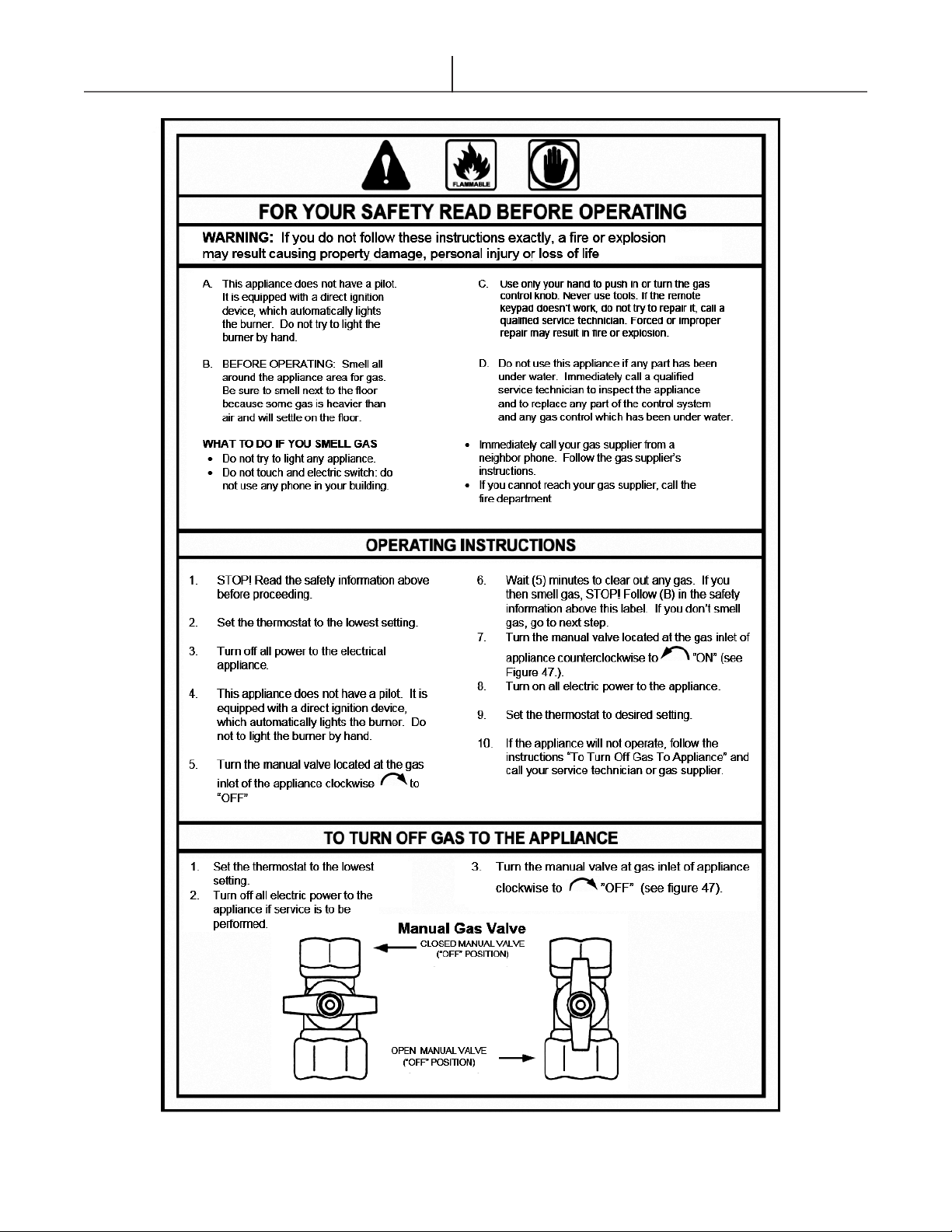
ΔShould overheating occur or the gas supply fails
to shut off, turn off the manual gas control valve
to the appliance. Contact a Service Technician
immediately.
ΔClearance must be in accordance with the local
installation codes and the requirements of the gas
supplier.
ΔNever operate the water heater unless it is vented
to the outdoors and has adequate air supply to
avoid risks of improper operation, re, explosion
or asphyxiation.
ΔDO NOT install this water heater directly on a
carpeted oor. A re hazard may result. The
water heater must be installed and adequately
supported on a metal or wood panel extending
beyond the full width and depth of the water
heater by at least 3 inches (76.2mm) in any
direction.
ΔFor safe operation, an ample supply of air
must be provided for proper combustion and
ventilation in accordance with the National Fuel
Gas Code ANSI Z223.1/NFPA 54 National Fuel
Gas Code CSA/B149.1 Natural Gas and Propane
Installation Codes or applicable provisions of the
local building codes. An insufcient supply of air
may result in a yellow, luminous burner ame,
carboning or sooting of the heat exchanger, or
create a risk of asphyxiation. Do not obstruct the
ow of combustion and ventilation air.
ΔThis unit is not intended to operate at gas supply
pressures other than those shown on the rating
plate. Exposure to higher gas supply pressure
may cause damage to gas valves, which can
result in re or explosion. If over-pressure has
occurred, such as through improper testing of
gas lines or emergency malfunction of the supply
system, the gas valve must be checked for safe
operation.
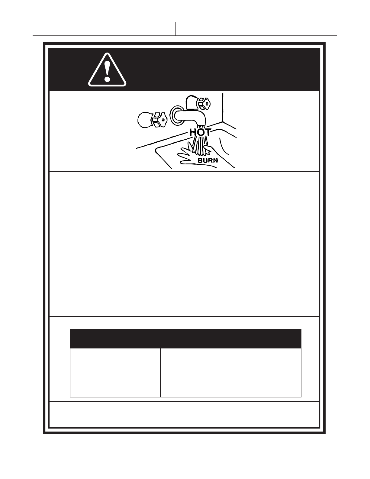
A thermostatic mixing valve must be added to
this system to prevent scalding, and as per local
codes and authorities.
1.2.2 Check The Rating Plate
ΔGlow water heaters come from the factory
congured for use with natural gas or propane.
Prior to installation, check the rating plate of
the water heater to ensure the unit matches
gas type, gas pressure, water pressure and
electrical supply. If the unit does not match the
requirements, do not install.
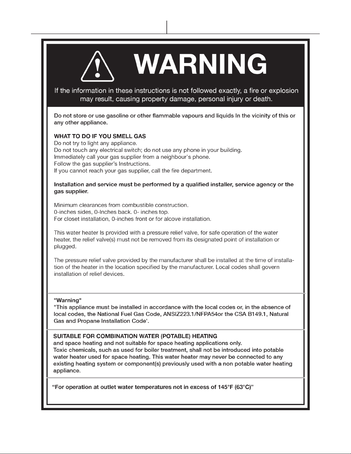
ΔThere is a risk in using fuel burning appliances in
rooms or areas where gasoline, other ammable
liquids or gas engine equipment or vehicles
are stored, operate or are repaired. Flammable
vapors are heavy and travel along the oor and
may be ignited by the igniter or main burner
ames causing re or explosion. Some local
codes permit operation of gas appliances if
installed 18 inches or more above the oor.
Flammable items, pressurized containers or any
other potential re hazardous articles must never
be placed on or adjacent to the water heater.
Open containers of ammable materials should
not be stored or used in the same room with the
water heater.
ΔDO NOT install the Glow water heater in areas
with excessive high humidity.
ΔDO NOT install the unit in locations where there
is excessive humidity, such as a bathroom, damp
crawl space and other areas with high levels of
humidity. This may cause the unit to malfunction.
ΔTo avoid possible electrical shock, DO NOT touch
the internal components of the water heater or the
power cord with wet hands.
ΔDO NOT splash excessive water on the water
heater when cleaning, as it is water resistant, not
water proof.
Δ Professionally qualied personnel in accordance
with current laws and standards and in line with
the manufacturer’s instructions must install the
appliance.
ΔThe commissioning of the water heater and any
subsequent works carried out on the appliance
must be performed by an appropriately qualied
technician.
ΔThe appliance must be used solely for the
purpose for which it has been designed and
manufactured: Domestic hot water production
and central heating if applicable (maximum set
point of 63°C/145°F). Any other use is deemed
as improper and as such dangerous. Under no
circumstances will the manufacturer be held
responsible for damage or injury to persons or
animals caused by errors in the installation and/or
use of the appliance, or through non-compliance
with current local and national standards and/or
the manufacturer’s instructions.
ΔThe installation, operation and maintenance
manual are an integral and essential part of the
product and must be kept with the appliance
always.
ΔThe warnings contained in this chapter have been
written for the appliance user, the installer and the
service technician.

Glow T150 & T180 Tankless Condensing Water Heater
5
Do not attempt to interfere with the
appliance in any way.
ΔAs dictated by current legislation, this appliance
must be installed exclusively by qualied and
certied personnel. Before starting the water
heater for the rst time, make sure that it is
connected to a water supply and central heating
system (maximum set point of 63°C/145°F)
compatible with its performance characteristics.
ΔPrior to start-up, the water pipes should be
ushed to remove any residues that could
compromise the operation of the appliance.
ΔThe electrical supply must be checked by a
qualied electrician to ensure that it can support
the maximum power absorption of the appliance,
as indicated on the appliance rating plate. In
particular, make sure that the wire ratings are
adequate for the power being used.
ΔDo not use adapters, multiple sockets or
extension cords to connect the appliance to the
power supply.
ΔThe appliance must be plugged into a 120v wall
receptacle in accordance with the current wiring
regulations.
ΔIf the wires are damaged in any way, switch off
the appliance and have the wire replaced by a
qualied technician.
Δ When the appliance is no longer required for use,
unplug the unit from the wall receptacle and draw
water from the unit.
Chapters 3, 4, & 5 of this manual must
be read carefully as they provide information
on the installation, commissioning and
maintenance of the appliance.
ΔAfter the removal of all the packaging, check that
the appliance has not been damaged. In case
of doubt, do not attempt to use the product but
refer to the supplier. Packing materials (cardboard
box, staples, plastic bags, polystyrene, etc.) must
not be left within reach of children in that these
items represent a potential hazard and must be
disposed of in a responsible manner.
ΔBefore carrying out any cleaning or maintenance
operations, disconnect the appliance from the
main electrical supply by unplugging the unit from
the wall.
ΔIn the case of a fault and/or malfunction in the
appliance, shut down the system. Do not interfere
with or attempt any repairs. Call for professionally
qualied technical assistance.
ΔAny warranty repairs to the appliance must be
carried out exclusively by the manufacturer’s
authorized trained service dealers using
original parts. Non-compliance with the above
requirements may compromise the safety of the
appliance and invalidate the warranty. In order to
guarantee the efciency of the appliance and its
correct operation, it must be serviced regularly by
professionally qualied personnel in line with the
manufacturer’s instructions.
ΔOnly original accessories or optional extras
(including electrical parts) must be used with the
appliance.
ΔShould there be a smell of gas present in the
room where the appliance is installed, DO
NOT attempt to activate any electric switches,
telephones or any other equipment that may
cause sparks. Open doors and windows
immediately to create a current of air and
ventilate the room. Shut-off the main gas supply
valve (at the meter), or on the cylinder in the case
of propane gas, and call an authorized service
contractor.
1.3 Safety Warnings
Carbon Monoxide Detectors
Many jurisdictions require the installation of carbon
monoxide detectors in buildings where a side wall
vented fuel burning appliance is installed. Installers
must abide by local code requirements regarding the
installation of CO detectors. The use of a certied
carbon monoxide detector is recommended but not
required by Glow Brand.

Glow T150 & T180 Tankless Condensing Water Heater
6
“In the State of Massachusetts only”
For all horizontally vented gas fueled equipment installed in every dwelling, building or structure used in
whole or in part for residential purposes, including those owned and operated by the Commonwealth and
where the side wall exhaust vent termination is less than seven (7) feet above nished grade in the area of
the venting, including but not limited to decks and porches, the following requirements shall be satised:
1. INSTALLATION OF CARBON MONOXIDE DETECTORS. At the time of installation of the side wall
horizontal vented gas fueled equipment, the installing plumber or gas tter shall observe that a hard wired
carbon monoxide detector with an alarm and battery back-up is installed on the oor level where the gas
equipment is to be installed and on each additional level of the dwelling, building or structure served by the
equipment. It shall be the responsibility of the property owner to secure the services of qualied licensed
professionals for the installation of hard wired carbon monoxide detectors.
a.In the event that the side wall horizontally vented gas fueled equipment is installed in a crawl space or
an attic, the hard wired carbon monoxide detector with alarm and battery back-up may be installed on
the next adjacent oor level.
b.In the event that the requirements of this subdivision cannot be met at the time of completion of
installation, the owner shall have a period of 30 days to comply with the above requirements,
provided, however, that during said 30 day period a battery operated carbon monoxide detector with
alarm shall be installed.
2. APPROVED CARBON MONOXIDE DETECTORS. Each carbon monoxide detector as required in
accordance with the above provisions shall comply with NFPA 720 and be ANSI/UL 2034 listed and IAS
certied.
3. SIGNAGE. A metal or plastic identication plate shall be permanently mounted to the exterior of the
building at a minimum height of eight (8) feet above grade directly in line with the exhaust vent terminal for
the horizontally vented gas fueled heating appliance or equipment. The sign shall read, in print size no less
than one-half (1/2) inch in size, “GAS VENT DIRECTLY BELOW. KEEP CLEAR OF ALL OBSTRUCTIONS”.
4. INSPECTION. The state or local gas inspector of the side wall horizontally vented gas fueled equipment
shall not approve the installation unless, upon inspection, the inspector observes carbon monoxide
detectors and signage installed in accordance with the provisions of 248 CMR 5.08(2)(a) 1 through 4.
Notice prior to installation
This appliance must be installed by a licensed professional in accordance with the Massachusetts Plumbing
and Fuel Gas Code 248 CMR Sections 2.00 and 5.00.
If you are not properly training, you must not install this unit.

Glow T150 & T180 Tankless Condensing Water Heater
7

Glow T150 & T180 Tankless Condensing Water Heater
8

Glow T150 & T180 Tankless Condensing Water Heater
9

Glow T150 & T180 Tankless Condensing Water Heater
10
DANGER
The temperature at which injury occurs varies with the person's age and time of exposure.
Water temperature over 125°F/52°C can cause severe burns instanly or death from scalding.
The slower response time of disabled persons increases the hazards to them. Never allow small children
to use a hot water tap, or to draw their own bath water. Never leave a child or disabled person unattend-
ed in a bathtub or shower.
The water heater should be located in an area where the general public does not have access to the
temperature control.
Lower water temperatures should be used to avoid the risk of scalding. It is further recommended, in all
cases, that the water temperature be set for the lowest temperature which satisfies the user’s hot water
needs. This will also provide the most energy efficient operation of the water heater and minimize scale
formation in the heat exchanger, thus prolonging the life of the unit.
Setting the water heater temperature at 120°F/49°C will reduce the risk of scalds. Some locations require
settings at specific lower temperatures. The table below shows the approximate time-to-burn relationship
for normal adult skin.
Hot water temperatures required for automatic dishwasher and laundry use can cause scalds and burns
resulting in serious personal injury and/or death.
Temperature
Setting
Over 170°F/77°C
160°F/71°C
150°F/66°C
140°F/60°C
130°F/54°C
120°F/49°C or less
Time to Produce 2nd, 3rd
Degree Burns on Adult Skin
Nearly instantaneous
About 1/2 second
About 1-1/2 seconds
Less than 5 seconds
About 30 seconds
More than 5 minutes
To protect against injury, you must install a tempering valve in the water system. This
valve will reduce point of discharge temperature by mixing cold and hot water in branch
supply lines. Such valves are available from the local plumbing supplier.
Table - Risks of Scalds

Glow T150 & T180 Tankless Condensing Water Heater
11
1.4 Product Conformity
All Glow Tankless Water Heaters are
ETL certied and possess technical
and functional characteristics that
comply with the following standards:
American National Standard/CSA
Standard for Gas Water Heaters
Volume III, Storage Water Heaters
with input Ratings above 75,000
Btu per Hour, Circulating and
Instantaneous. Conforms to ANSI
STD Z21.10.3:2019, certied to CSA
STD 4.3-2019.
The materials used, such as copper,
brass, stainless steel, etc. form a
compact, homogeneous, highly
functional unit that is easy to install
and simple to operate. In its simplicity,
the wall-mounted appliance is
equipped with all the appropriate
accessories required to make it
a fully independent water heater
capable of satisfying domestic hot
water production and central heating
(maximum set point of 63°C/145°F)
needs if installed. All water heaters
are fully inspected. This manual must
be kept in a safe place and must
accompany the water heater at all
times.
Glow Brand will not be held
responsible for any misinterpretation
of this manual.
Glow Brand will not be held
responsible for the consequences
in the case of non-observance of
the instructions contained in this
manual or in the case where actions
not specically described herein are
undertaken.
MENU
ENTER
RESET
UP
DOWN
Figure 1.1 - Glow Tankless Water Heater

Glow T150 & T180 Tankless Condensing Water Heater
12
2. Technical Characteristics
2.1 Technical Data
Table 2.1
Specication T-150 NG T-150 LP T-180 NG T-180 LP
Heat Input - Min Btuh (kW) 16,000 (4.7) 16,000 (4.7) 20,500 (6.0) 20,500 (6.0)
Heat Input - Max Btuh (kW) 156,000 (45.7) 156,000 (45.7) 194,000 (56.8) 194,000 (56.8)
Energy Factor (EF) - - 97% 95%
Unied Energy Factor (UEF) 94% 91% 95% 93%
Domestic Output - Max Btuh (kW) 154,860 (45.3) 151,720 (44.5) 188,000 (55.1) 188,000 (55.1)
Min Inlet Gas Pressure - inch w.c. 3.5 8.0 3.5 8.0
Max Inlet Gas Pressure - inch w.c. 10 13 10 13
Gas Valve Outlet Pressure - inch w.c. -0.03
Power (120Vac/60Hz) - Watts 104 99 119
Min DHW Temperature - °F (°C) 102 (39) 102 (39)
Max DHW Temperature - °F (°C) 145 (63) 145 (63)
Min Water Pressure - Psig (bar) 30 (2.1) 30 (2.1)
Max Water Pressure - Psig (bar) 150 (10.3) 150 (10.3)
Min ow rate to activate DHW - usgpm (lpm) 0.6 (2.27) 0.6 (2.27)
DHW Flow at ΔT 35°F - usgpm (lpm) 8.8 (33.3) 8.7 (32.9) 10.7 (40.2)
DHW Flow at ΔT 45°F - usgpm (lpm) 6.9 (26.1) 6.7 (25.3) 8.4 (31.8)
DHW Flow at ΔT 72°F - usgpm (lpm) 4.3 (16.2) 4.2 (15.9) 5.2 (19.7)
DHW Flow at ΔT 77°F - usgpm (lpm) 4.0 (15.1) 3.9 (14.7) 4.9 (18.6)
Vent/Air-Intake Pipe Diameter - inches (mm) 2 (51) or 2½ (63½) or 3 (76)
Max Equivalent Vent Length 2” (each side) - ft 30 25
Max Equivalent Vent Length 2 ½” (each side)- ft 65 50
Max Equivalent Vent Length 3” (each side) - ft 125 100
Vent Clearances to Combustibles - inches (mm) 0 (0)
Cold Water In Connection - MPT, inches ¾
Hot Water Out Connection - MPT, inches ¾
Gas Connection - MPT, inches ¾
Dimensions H x W x D - inches (mm) 28 x 16.5 x 13.2
(711 x 425 x 335)
28 x 16.5 x 17.2
(711 x 425 x 437)
Weight (empty) - lbs (Kg) 80 (36) 90 (41)

Glow T150 & T180 Tankless Condensing Water Heater
13
2.2 Dimensions
28.0
INLET
HOT WATER
OUTLET GAS INLET
COLD WATER
CONDENSATE OUTLET
11.1
6.8
2.1
3.5
2.9
9.9
6.8
11.6
AIR EXHAUST
VENT INTAKE
5.7
17.2
16.5
6.7
5.6
Figure 2.2- Glow T180 Dimensions
28.0
INLET
HOT WATER
OUTLET GAS INLET
COLD
WATER
CONDENSATE
OUTLET
11.6
2.2
1.8
6.6
2.6
4.8
2.4
7.8
AIR EXHAUST
VENT INTAKE
5.8
13.2
16.5
6.7
5.6
Figure 2.1 - Glow T150 Dimensions
LEGEND
Gas Inlet Ø ¾” NPT
Cold Water Inlet Ø ¾” NPT
Hot Water Inlet Ø ¾” NPT
Condensate Outlet Ø 1”

Glow T150 & T180 Tankless Condensing Water Heater
14
2.3 Unit Performance
esiRerutarepmeT
(Delta T)
Temperature Rise Curve (Incoming Water 14°C / 58°F)
Water Flow (GPM)
150
125
100
75
50
25
00 0.5 1.0 1.5 2.0 2.5 3.0 3.5 4.0 4.5 5.0 5.5
66
52
38
33
19
-4
-18
°C / °F
Table 2.1: T150
Water Flow (GPM)
Pressure Drop Curve (Incoming Water 58˚F)
0 0.5 1 1.5 2 2.5 3 3.5 4 4.5 5
16
14
12
10
8
6
4
2
0
Pressure Loss (PSI)
Table 2.1: T150

Glow T150 & T180 Tankless Condensing Water Heater
15
0
25
50
75
100
125
150
01234567891011
Water Flow (GPM)
Temperature Rise (Delta T)
Temperature Rise Curve (Incoming Water 14°C/58°F)Temperature Rise Curve (Incoming Water 14°C/58°F)Temperature Rise Curve (Incoming Water 14°C/58°F)Temperature Rise Curve (Incoming Water 14°C/58°F)Temperature Rise Curve (Incoming Water 14°C/58°F)Temperature Rise Curve (Incoming Water 14°C/58°F)
-18/
°C / °F
-4 /
19/
33/
38/
52/
66/
0
5
10
15
20
25
30
35
40
45
50
55
60
01234567891011
Pressure loss (PSI)
Water Flow (GPM)
10
20
110
100
90
70
60
50
30
40
80
130
120
Pressure Loss (ft head)
Pressure Drop Curve (Incoming Water 14°C/58°F)
Table 2.3: T180
Table 2.4: T180

Glow T150 & T180 Tankless Condensing Water Heater
16
2.4 Internal Parts Of The Water Heater
2
3
8
17
21
22
20
5
6
23
24
25
26
18
19
4
7
13
9
1
28
29
15
27
11
16
14
12
10
LEGEND
1. COMBUSTION AIR INLET ADAPTER
2. BLOCKED FLUE SWITCH
3. 3/16” BARBED TEE
4. IGNITION CONTROL BOARD (ICB)
5. STAINLESS STEEL HEAT EXCHANGER
6. IGNITION TRANSFORMER
7. IGNITION ELECTRODE
8. 3/16” DIA. SILICONE HOSE
9. PREMIXED BURNER ASSEMBLY
10. VENTURI ASSEMBLY
11. ELECTRONIC WATER FLOW SENSOR
12. GAS VALVE
13. DISPLAY BOARD
14. COLD WATER INLET
15. INLET WATER SCREEN
16. GAS CONNECTION
17. CONDENSATE HOSE
18. HOT WATER OUTLET
19. HOT WATER SENSOR
20. CONDENSATE TRAP
21. PRE MIX FAN
22. INLET WATER SENSOR
23. HEAT EXCHANGER OUTLET SENSOR
24. HI LIMIT SWITCH
25. IONIZATION ELECTRODE
26. FLUE SENSOR
27. 3/16” NYLON HOSE BARB
28. COMBUSTION ANALYZER PORT
29. EXHAUST FLUE ADAPTER
Figure 2.3- T180 internal parts

Glow T150 & T180 Tankless Condensing Water Heater
17
2.5 Display & Control Circuit Board
2.5.1 LCD Display
2.5.2 Status Display Symbols
The table below describes the function of each symbol.
Located on the top and bottom corner on the right side of the screen.
Indicates when the up/down buttons should be used to set a parameter.
Located on top and bottom corner on the left side of the screen.
This symbol is shown when scrolling through the User menu.
Temperature in °Celsius, this value is displayed with a comma (e.g. 20,5 °C).
If the value of the temp. is set to °F, the °C- icon will not show
Demand for frost protect is active, the temperature display shows the actual
ow temperature
Alarm condition*: the alarm code is displayed (blinking) on the temp. display:
A xx = Lockout error number E xx = Blocking error number
Indicates appliance burner is ON
Domestic Hot Water demand: the temperature display shows the actual ow
temperature
Preheat Domestic Hot Water
Standby
ini – Initializing software
con – Connecting display with controller and start communication
Figure 2.4- Water Heater display
Status Symbol Description
Table 2.4

Glow T150 & T180 Tankless Condensing Water Heater
18
2.5.3 Control Button Layout
5 different buttons are present on the LCD Display for
operating the module. The buttons are positioned to the
right of the display. (see g. 2.4)
With these ve buttons various layouts are possible.
The display layout has the most frequent keys ([UP],
[ENTER] and [DOWN]) placed vertically in the middle,
which combines convenient navigation with a user
friendly look, due to the silicone keypad.
The table below describes the button functions. (Table
2.5)
Button Function Description
RESET
Press and hold for 5 sec. to switch the display board ON or OFF.
Press to reset the appliance in case of a Lock-out error or Press to cancel an altered
parameter
MENU Press to enter the User menu or Press for 10 sec. to enter the Service menu
ENTER Press to conrm when you have selected a parameter or Press to conrm an altered setting
UP Scroll up or Increase the value (of a parameter)
DOWN Scroll down or Lower the value (of a parameter)
2.5.4 Direct Adjustments of DHW Set point via Main Display Screen
The DHW set point can be directly adjusted in the main screen only when the unit is in standby [ ].
In this case, the following icons are shown, including the set point temperature that is being altered.
Icons Description
DHW set point can be altered by using the [UP] and [Down] buttons
2.5.5 Error Displayed on Screen
In case of a Warning, Error-/Alarm condition, the Blocking (‘E’), Locking (‘A’) or Attenuations (‘n’) error will
continually ash. The User menu is inaccessible and can only be reset by pressing [RESET]. See section 6-
(‘Lock Out & Warnings’)
Figure 2.5- Control panel
MENU
UP
ENTER
DOWN
RESET
Table 2.5
Table 2.6

Glow T150 & T180 Tankless Condensing Water Heater
19
2.6 User Menu
Open the User view menu by pressing the [MENU] button once. This menu can be used to look at the values of a
selection of parameters (read-only parameters) or to view the sensor temperatures.
The scheme below shows how to operate of the User menu in some simple steps:
The following table describes of the parameters in the User menu, which are all read-only.
Table 2.7
Table 2.8
* The value of these parameters are given in RPM. Because the display can only show 3 digits, the number on the screen has to be
multiplied times 10. For example, when the display shows the number 20, it means that RPM is 20x10, i.e. RPM is 200.
** The value of this parameter is given with a factor of x100. For example, when displaying 001 this means 100 successful ignitions.
*** The value of this parameter is the number of hours times 10. For example, if the number on the display says 50, it means 50x10, which
is 500 hours.
**** The value of this parameter is the number of days x 10. For example, if the number on the display says 36, it means 36x10, which is 360
days.
* If these buttons are no longer operated for 2 sec. the parameter no. and the current value displayed will show with intervals of 2 sec.
** In case of a non-adjustable parameter, the current value will be displayed continuously.
Parameter Description Value
100
Heat Exchanger outlet sensor
°C or °F
101
Outlet water sensor
°C or °F
102
Flue gas temperature sensor
°C or °F
103
Inlet water sensor
°C or °F
108
Ionization current
µA
109
DHW Flow
L/min
111
DHW pump status
Does Not Apply
140
Actual fan speed
X 10 RPM *
141
Ignition fan speed
X 10 RPM *
142
Minimum fan speed
X 10 RPM *
143
Maximum fan speed
X 10 RPM *
151
Last Lockout number
#
152
Last Blocking error
#
153
Number of flame failures
#
154
Number of successful ignitions
X 100**
155
Number of failed ignitions
#
157
Total hours of operation for the DHW
X 10 Hrs***
158
Total days of operation of the burner
X 10 Days****
159 Interval between lockout errors “00-59” = 0-59 minutes
“01h-23h” = 1-23 hours
“01d-06d” = 1-6 days
“01u-63u” = 1-63 weeks
160 Interval between blocking errors “00-59” = 0-59 minutes
“01h-23h” = 1-23 hours
“01d-06d” = 1-6 days
“01u-63u” = 1-63 weeks
1. Enter the
User Menu
2. Scroll though
Parameter List
3. Select parameter
4. Alter value of
parameter
5. Confirm / cancel
alteration
Press [MENU]
button once
Scroll through the
parameter list with the
[UP] / [DOWN]
buttons*
10 seconds of no
action automatically
return to the status
screen.
Select a parameter to
alter/read-out it’s value
by pressing
[ENTER]* *
10 seconds of no
action automatically
return to the status
screen.
Alter a value of the
parameter with the
[UP] / [DOWN] buttons.
When the parameter is
being altered, the value
on the display will blink.
Confirm (save) with
[ENTER] or
Cancel with [RESET]
After saving/cancelling
you automatically return
to the installer selection
(1).

Glow T150 & T180 Tankless Condensing Water Heater
20
2.7 Service Menu
The table below shows how to enter the Service Menu in some simple steps:
* If these buttons are no longer operated for 2 sec. the parameter no. and the current value displayed will show with intervals of 2 sec.
** In case of a non-adjustable parameter, the current value will be displayed continuously.
Parameter
No.
Description Value Default
202 Appliance model selection
1:
T180 NG
2: T180 LP
3: T150 NG
4: T150 LP
1: T180 NG
203 Temperature Unit selection
°F/°C
°F
208 Reset
ON: DHW Mode “ON”
OFF: DHW Mode “OFF”. No hot water
ON
210 System test power
OFF: Exit from system test.
rEg: N/A
FAn: Fan rotates at maximum RPM
(Flow water through heater for following tests)
Lou: Burner fires at minimum power
Ign: Burner fires at Ignition power
Hig: Burner fires at maximum power
OFF
214 Display test
when [UP] button is pushed all icons and
LEDs will
light-on.
Press [RESET] to go back to the settings menu.
N/A
219 Pre-heat function
0: No mode
1: Anti-freeze
2: ECO
3: Comfort
1: Anti-freeze
280
Service Reminder.
ON, OFF, rSt (reset)
OFF
281
Service Interval
Days x 10
Range: 0-100
Table 2.9
Table 2.10
The following table shows the available parameters in the Service menu.
11.. EEnntteerr tthhee
SSeerrvviiccee MMeennuu
22.. SSccrroollll tthhoouugghh
PPaarraammeetteerr LLiisstt
33.. SSeelleecctt ppaarraammeetteerr 44.. AAlltteerr vvaalluuee ooff
ppaarraammeetteerr
55.. CCoonnffiirrmm // ccaanncceell
aalltteerraattiioonn
Hold [MENU] for 5
seconds.
Display will alternately
flash parameter 207
and its value set point.
Scroll through the
parameter list with
the [[UUPP]] // [[DDOOWWNN]]
buttons*
10 seconds of no
action automatically
return to the status
screen.
Select a parameter to
alter/read-out it’s
value by pressing
[[EENNTTEERR]* *
10 seconds of no
action automatically
return to the status
screen.
Alter a value of the
parameter with the
[[UUPP]] // [[DDOOWWNN]] buttons.
When the parameter is
being altered, the value
on the display will
blink.
Confirm (save) with
[[EENNTTEERR]]
or
Cancel with [[RREESSEETT]]
After saving/cancelling
you automatically
return to the installer
selection (1).
This manual suits for next models
1
Table of contents
Other GLOW Water Heater manuals
Popular Water Heater manuals by other brands

Rheem
Rheem MPs Series Owner's guide and installation instructions

A.O. Smith
A.O. Smith ATI-305-N Selection guide

Alternative Energy Company
Alternative Energy Company Energie Solar Box owner's manual

ASKOMA
ASKOMA AHIR-BI-plus-3.5 user manual

Haier
Haier ES30V-A3 instruction manual

Solar Energy
Solar Energy WWKS 300 Installation and operating manual

Slant/Fin
Slant/Fin VICTORY II VHS Series Specification sheet

Suburban
Suburban SW4P Installation and operation manual

Kenmore
Kenmore 153.317232 owner's manual

proTough
proTough NR111-DV installation manual

Ariston
Ariston Eureka instruction manual

STIEBEL ELTRON
STIEBEL ELTRON HDB-E 12 Si Operation and installation