4.1
Preliminary
Checks
Remove
front
case
and
conuols
uay. Turn the
gas
"Ofl', turnwateron and
checkfor watcrleakage
around
thcheater.
Relit thcoutcr
cascand
sccurc.
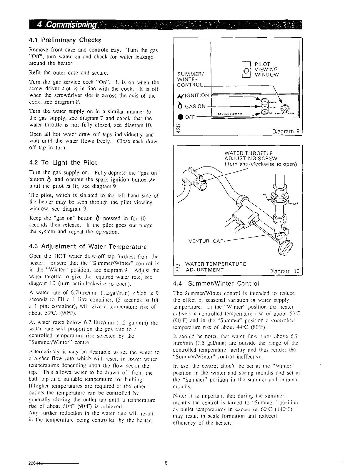
Turnthcgas
servicc
cock
"On". It is on when
the
screw
driverslot is in linc with thecock. It is otf
whenthescrewdriver
slotis acrosstheaxis
of thc
cock,
secdiagram8.
Turn
thc
watcr
supply
on in a similar
manncr
the
gas
supply,sccdiagram
7 andchcck
that
waterthrottlc
is not fully closcd,
sec
diagram
Opcn
all hotwatcrdrawoff taps
individually
wait until thc waterflorvsfrccly. Closc
each
off taoin turn.
lrl
the
10.
and
draw
4.2
To Lightthe Pilot
Turnthc
gas
supply
on. Fully
depress
the
"grs on"
button
I andoperate
thespark
ignitionbutton,Arz
untilthc
pilotis lit, seediagram9.
Thc
pilot,
which
is situatcd
to thclcft hand
sidc
oi
thc
hcater
may
bc sccn
throughthe
pilot
vicrving
window,
sec
diagram
9.
Kccpthc "gas
on" buLton
I pressedin for l0
scconds
thcn
rcleasc.If thcpilot gocs
out purgc
thcsystcmand
rcpcatthc
opcration.
4.3Adjustmentof Water
Temperature
Opcn thc HOT water draw-off up furrhcst
from thc
hcatcr. Ensurc
thatthe "SummerAVinter"
control
is
in thc "Wintcr" position,
sccdiagram
9. Adjustthc
watcr
[hrottlcto givc thc rcquircd
\viltcr
ratc,
scc
tliagrarn
i0 (turn anti-clockrviscto opcn).
A watcrratc ol 6.7litrc/rnin
(i.5gal/rnin)r \ii:h is 9
scconds
to fill a I litrc contirincr,
(5 scconcjs
;o t'ill
a I pint
contlincr),
will givc a [cmpcraturcriscol.
rbout 50"C,
(90"R.
Ar watcrratcs
bclorv
6.7 litrc/rnin
(1.5 g:rl/rnin)
thc
\\':.ltcrratc will proportion thc sas ratc to a
controllcd
lcmpcralurc
riscsclcctcd
by'thc
"SumrncrAVintcr"
control.
Ahcrnutivcly
it may bc dcsirablc
to sct thc \\,atcr
to
lu
highcrflow ratc which rvill rc.sulIin lorvcr
rvirtcr
tcn)pcrilturc.,i
dcpcndingupon thc llo\\' sr'tilt thc
tilp. This allorvs watcr to bc tlrarvrtot't'
l'rom thc
butlr
t:.rp
at a suiublc.
[ctnpcri.lLurc
lbr bitthins.
ll'highcr tcrnpcrilturcs
rrc rcquircd
at thc othcr
orrtlcts
thc tcrllpcraturc
ciln bc controll'--d
bv
grlrlualll'
closirt{ thc out['t tap until a tcrl]pcri.lturc
risc ol' about -iO"C
(90"F) i.sachicvcd.
'\n1' lirrthcrrctluction
in Ihc rr'utcr
rat.c
*'ill rcsult
irrtlrc tr'rnpcrlturcbcingcontrollctl
b1'thc hcutcr.
4.4 SummerMinter
Control
Thc SummcrAVintcr
control
is intcndcd
to rcducc
the eflcct
of scasonal
variationin u'atcr
supply'
tcmpcrilturc.
In thc "\\'intcr" position
thc hcltcr
clclivcrs
a controllcti
tctnpcraturc
riscol abouL
50''C
(90"F)
and in thc "Sumrncr"
pt-rsition
a controllc'il
tcmpcri.rturc
ri.scof about
-l-l"C (80'F).
It shoulri
bc notctl lhat *ittcr llorv ratcsitbovc 6.7
litrc/min
(1.5gal/rnin):rc outsiclc
thc ranScof thc
controllcd
tcmpcritturc
tacilit,vand thusrcndcr
thc
"surnrncrAVintcr"
control
incfl'cctivc.
In usc,
thc controlshould
bc sct at thc "\\'intcr"
positionin thc s'intcr
and spring
rnonthsttrtd
sctItt
thc "Summcr"position
in thc sunrlncr
antlauttlllln
rnonths.
Note: lt is importltnt
thrt tluring
lhc sutl]ttlt-r
rnonth.Jthc control
is turnctl
ttl "Surnrncr"
llosititlrr
i,l:ioutlct tctltpcrilturcs
in crccss tll' (10''C
(lJ(I'F)
rnuy
rcsult
in scllc lbrrttation
lttltl
rctlucctl
cll'icicncy
ol' thc he-iltcr.
P
ILOT
VIEWING
WINDOW
SU
MMER/
WINTER
CONTROL
//rGNlTlON
I cot
ot
O
orr
T Diagram
9
WATERTHROTTLE
ADJUSTING
SCREW
(Turn
anti-clockwise
toopen)
N
VENTURI
WATER
TEMPERATURE
ADJUSTMENT I-\i^^zrm 1A
ulo9rqrrl lv
zuo{ |o


 Operation and maintenance instructions")