Glowworm SS 175 User manual

12563
Unvented hot water
storage cylinders
SS 115-SS 150-SS 175-SS 200
SS 250-SS 300
Instructions for Use
Installation and Servicing
www.glow-worm.co.uk

For customer service call:
01773 828100
Technical helpline: 01773 828300
For General and Sales enquiries:
Tel. 01773 824141
Fax: 01773 820569
To register your Glow-worm appliance call:
0800 073 2142
Guarantee Registration
Thank you for installing a new Glow-worm cylinder in your home.
Glow-worm appliances' are manufactured to the very highest standard so we are
pleased to offer our customers' a Comprehensive Guarantee.
We recommend you complete and return your Guarantee Registration Card as soon
as possible.
If this card is missing you can obtain a copy or record your registration by
telephoning Glow-worm's own service organisation on 01773 828100.
Our Guarantee gives you peace of mind plus valuable protection against
breakdown.
Benchmark places responsibilities on both manufacturers and installers. The purpose is to ensure that customers are
provided with the correct equipment for their needs, that it is installed, commissioned and serviced in accordance with
the manufacturer’s instructions by competent persons and that it meets the requirements of the appropriate Building
Regulations. The Benchmark Checklist can be used to demonstrate compliance with Building Regulations and should
be provided to the customer for future reference.
Installers are required to carry out installation, commissioning and servicing work in accordance with the Benchmark
Code of Practice which is available from the Heating and Hotwater Industry Council who manage and promote the
Scheme.
Visit www.central heating.co.uk for more information.
2

Contents
The instructions consist of three parts, User, Installation and Servicing Instructions. The
instructions are an integral part of the appliance and must, to comply with the current
issue of the Gas Safety (Installation and Use) Regulations, be handed to the user on
completion of the installation.
CONTENTS DESCRIPTION SECTION PAGE
Testing and Certication 4
Design Description 4
Technical Data 1 5
Instructions for Use 2 6
Note to Installer 3 8
Installation 4 8
Commissioning 5 15
Maintenance 6 15
Fault Finding 7 16
INTRODUCTION
INSTALLATION
MAINTENANCE
3

NOTE: Only the correct immersion heater containing a safety
overheat thermostat may be used for replacement.
Applications
The Glow-worm cylinder can be connected to any UK
standard boiler.
Typical applications
Single bathroom property:
Glow-worm cylinder SS 115
Single bathroom property with an en-suite shower room:
Glow-worm cylinder SS 115 / SS 150
Two bathroom property:
Glow-worm cylinder SS 150 / SS 175
Two bathroom property with an en-suite shower room:
Glow-worm cylinder SS 175 / SS 200
Larger properties:
Glow-worm cylinder SS 250 / SS 300
Commercial use: size depending upon hot water
requirements.
NOTE 1: Select the appropriate boiler to match the heating
load (with the normal allowance for heating up from cold)
plus an allowance for heating the hot water cylinder. Typically
it is practice to allow an additional 2-3 kW for the hot water
production.
NOTE 2: Consideration should be given to the use of a larger
size of cylinder than shown above where high water demands
are likely.
The Glow-worm range of unvented hot water storage
cylinders are indirectly heated cylinders which are designed
for use with UK standard boilers in hot water supply systems.
Glow-worm cylinders are available in six sizes; 115, 150, 175,
200, 250 and 300 litre.
The cylinders are of stainless steel construction, insulated
with EPS and enclosed in a decorative casing. They are
supplied with all necessary cold and hot water controls and a
2 port valve for control of domestic hot water.
The Glow-worm cylinders operate using a mains water
pressure supply and do not require a feed from a cold water
storage tank. The Glow-worm cylinders have 22 mm DHW
outlet and cold water mains inlet connections for optimum ow
rate. To achieve optimum performance from the Glow-worm
cylinder an adequate cold water mains supply pressure and
ow rate must be available (see section 4.2: Mains Water
pressure).
DHW Temperature Control
The Glow-worm cylinder is supplied tted with an adjustable
domestic hot water (DHW) thermostat with thermal cut-
out and manual reset button which controls, via a 2 port
motorised valve, the temperature of the water in the Glow-
worm cylinder.
The external electrical controls should be wired to the 2 port
valve and cylinder thermostat in the normal way, as shown in
the section Electrical Connections and Controls.
CH Control
Central heating is controlled by a separate 2 port valve
in conjunction with suitable external controls, such as a
programmer, room thermostat and thermostatic radiator
valves.
Immersion Heater
Glow-worm cylinders are also provided with an auxiliary back
up 3 kW electric immersion heater, including an adjustable
thermostat, thermal cut-out and manual reset button and are
tted behind the front panel.
Testing and Certication
This product has been assessed and complies with the
requirements of the Building Regulations for unvented hot
water storage systems and must not be altered or modied in
any way.
Any alteration not approved by Glow-worm, could invalidate
the certication, warranty and may also infringe the current
issue of the Statutory Requirements.
WARNING: We cannot accept responsibility for any damage
which may occur as a result of non-observance of these
instructions.
Subject to alteration.
Spare Parts
IMPORTANT: Use only genuine spare parts supplied by
Glow-worm.
Testing and Certication
Design Description
Assessed and found to comply with
the requirements of the Building
Regulations for unvented hot water
storage systems.
WRAS Approval No.
0501063
4

NOTE: Heat up time based on a primary ow rate of 15 l/min at 82 °C.
Temperature rise is from 15 °C to 65 °C for 70 % of the cylinder volume.
SS 115 SS 150 SS 175 SS 200 SS 250 SS 300 Unit
Size 115 150 175 200 250 300 litres
Nominal DHW ow from
GW 115/150/175/200
GW 250/300
15 l/min @ 60°C
20 l/min @ 60°C
Max. water supply pressure 10 bar
Expn. vessel charge pressure 4 bar
Operating pressure 3.5 bar
Pressure reducing valve 3.5 bar
Expansion relief valve 6.0 bar
T/P valve 95 / 7.0 °C bar
Net weight 28 30 33 39 44 49 kg
Weight (full) 145 175 205 245 310 340 kg
Height 969 1179 1339 1499 1789 2109 mm
Cylinder connections:
Cold mains inlet 22 mm compression
DHW outlet 22 mm compression
Balanced pres. cold water outlet 22 mm compression
DHW secondary return G 3/4
CH ow 22 mm compression (on 2 port valve)
CH return 22 mm compression
Electrical connections:
3 kW Immersion heater 230/240 V. 50 Hz
Two port valve 230/240 V. 50 Hz
Cylinder thermostat 230/240 V. 50 Hz
Coil Specications:
Heat loss 1.7 1.9 2.0 2.1 2.3 2.5 kW/24h
Heatup time 23 25 26 30 38 49 min
Recovery 20 21 23 27 33 44 min
SS 300
SS 250
SS 200
SS 175
SS 150
SS 115
12738
1 Technical Data
5

2.3 How to use your Glow-worm hot water
cylinder
Your boiler and Glow-worm unvented hot water cylinder will
provide both central heating and mains pressure hot water.
Check that the boiler is operational as detailed in the
instructions for use supplied with the boiler.
The domestic hot water thermostat on the Glow-worm cylinder
can be set from 20°C to 65°C. The desired temprature will
be set by the installer while commissioning the Glow-worm
cylinder (normally a setting of 60°C is adequate).
NOTE: In hard water areas the DHW temperature selected
should not exceed this setting to avoid possible scale build-up.
If a programmer has been tted to control the central heating
and hot water, check that this is set to the desired on and off
periods.
The boiler will then operate automatically to heat the cylinder
contents at the desired times to the temperature selected.
When domestic hot water is used, the boiler will operate to
re-heat the cylinder as required.
2.4 Immersion heater
The electric immersion heater behind the front panel is
provided as a back up means of water heating and is not
intended for use at the same time that the boiler is heating the
cylinder.
2.5 Important Notes
Shutting down the Glow-worm cylinder
To shut down the heating and hot water system for short
periods, simply turn off the boiler as shown in the instructions
supplied with the boiler.
Frost protection
Please ensure that if you are absent during a period of frost
the central heating system remains in operation and the
rooms and Glow-worm cylinder are kept above freezing
point. It must be remembered however that the boiler will be
automatically switched off by built-in monitoring devices if
certain faults occur, e. g. interruption in the gas or electricity
supply.
Alternatively you can drain the central heating system, boiler
and Glow-worm cylinder. Please contact your Installer.
Care and Maintenance
The casing of the Glow-worm cylinder may be cleaned with
a damp cloth and a little soap. Do not use any abrasive or
solvent material which could damage the case or ttings.
It is important that your hot water cylinder is serviced annually
by a competent person approved at the time by the Health
and safety Executive. Please contact your installer or Glow-
worm 01773 828100 for further details.
2.1 Introduction
Your Glow-worm unvented hot water cylinder together with
a boiler, provides you a modern, efcient, high performance
heating and hot water system.
Because your Glow-worm hot water cylinder is supplied with
water directly from the mains, you get the benet of mains
pressure hot water at your hot taps, without the need for
storage tanks in the loft and without a hot water pump. The
Glow-worm cylinder is made from high quality stainless steel
within an easy clean casing. The cylinder is fully insulated
using environmental friendly EPS insulation to help keep
your hot water running costs at a minimum, and protect the
environment!
Your Glow-worm cylinder is tailor made to accompany a
Glow-worm boiler as well as any other UK standard boiler. All
Glow-worm boilers are equipped with 'built-in' energy saving
technology, such as burner modulation, anti cycling control
and high efciency heat exchangers.
Please read these instructions carefully to ensure that you get
the very best out of your heating and hot water system.
2.2 Liability
WARNING: We can accept no liability whatsoever for damage
or injury resulting from failure to observe these instructions.
Specied use
Glow-worm unvented cylinders are made to full the latest
technical specication and ofcial safety regulations.
These cylinders are designed for use with UK standard boilers
for use in hot water supply systems.
Use of this type is entirely at the owner's risk.
The term 'specied use' also covers observance of the
operating and installation instructions, along with adherence
to the servicing schedules.
NOTE: The commissioning should be carried out by a
competent person approved at the time by the Health and
Safety Executive and in accordance with the current issue of
BS6798.
The Benchmark documents, for both boiler and cylinder,
should be completed by the installer and/or commissioning
engineer and handed to the user. The Benchmark checklist
and service record are located on the inside back pages of
these instructions.
Do not remove or adjust any component part of this cylinder.
In the unlikely event that your Glow-worm develops a fault,
such as a ow of hot water from the discharge pipe, switch
the boiler and immersion heater off and contact Glow-worm or
your installer.
NOTE: If the Glow-worm cylinder is installed in a cupboard
used for airing purposes please ensure that clothing or
other articles are not placed on the cylinder or its associated
controls.
NOTE: Access should always be maintained to allow
operation of the domestic hot water thermostat control.
2 Instructions for Use
6

Diagram 2.1
12528
2.6 Guarantee
Glow-worm offers a guarantee of 25 years for the stainless
steel vessel against faulty materials or manufacture:
The following information is important as without it your
guarantee may be invalid.
1. The warranty will become invalid if the damage is
due to scaling, frost damage, transient voltages,
lightning strikes or any act of vandalism or misuse.
2. The proof of purchase must be produced in the event
of any warranty claim (bill of sale).
3. The Glow-worm cylinder must be installed by a
competent person approved at the time by the Health and
safety Executive to the prevailing standards, installation book
and building regulations at the time of installation.
4. The benchmark cylinder commissioning checklist must be
completed on installation and kept up to date.
5. The Glow-worm cylinder must be serviced annually.
6. The installation must be in an appropriate location
and its use is restricted to potable water (chloride
levels less than 200 mg/l).
7. Tampering or modication will invalidate the warranty.
8. The guarantee card must de completed and returned
to Glow-worm, within 30 days of purchase.
9. The guarantee does not cover the effects of scale.
For all other Glow-worm parts (electrical, thermal controls,
valves and design elements Glow-worm carry a 2 year
guarantee.
2 Instructions for Use
7

4.1 Siting
IMPORTANT. With regards to the Manual Handling
Operations, 1992 Regulations, the following lift operation
exceeds the recommended weight for a one man lift.
Locate the Glow-worm cylinder in the building in the most
convenient position ensuring that:
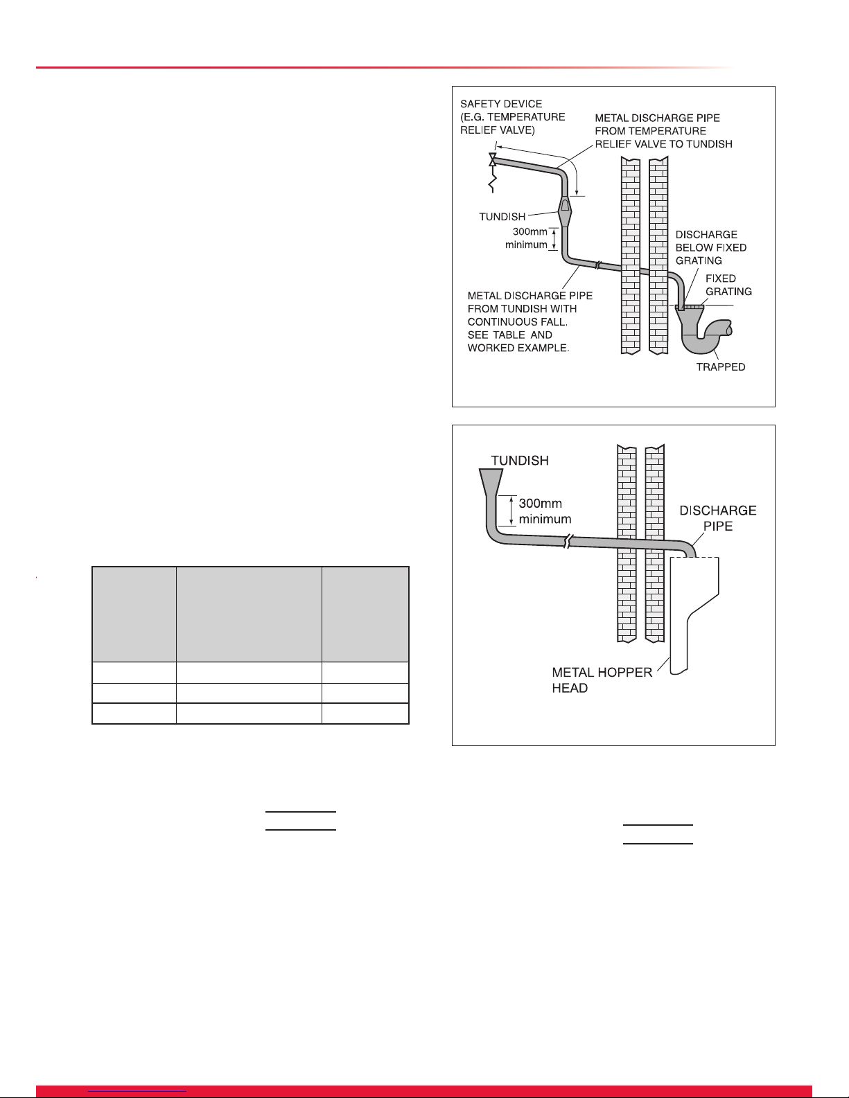
1. The discharge pipe from the tundish can be installed with a
minimum fall of 1:200 and must be terminated in a safe and
visible position (see section 4.4 Discharge pipework).
2. The base chosen for the unit is level and capable of
supporting the weight of the cylinder when full (see section 1
Technical Data).
3. The installation site is frost-free. If necessary provide a frost
protection thermostat.
4. Access is available for user operation of the DHW
temperature control under the front panel.
5. Suitable clearances exist to allow installation, checking and
repressurising of the expansion vessel.
6. The installation site chosen does not result in excessive
”dead leg” distances, particularly to the point of most frequent
use.
7. A suitable cold mains water supply pipe can be provided to
the Glow-worm cylinder direct from the main water stop valve
of the building.
8. The cylinder is factory equipped with adjustable feet to
allow for uneven oor surface.
This product has been assessed and found to comply with
the requirements of the Building Regulations for unvented hot
water storage systems and must not be altered or modied in
any way.
The installation must be carried out by a competent person
approved at the time by the Health and Safety Executive
and be in accordance with the relevant requirements of the
Local Authority, Building Regulations, Building Regulations
(Scotland), Building Regulations (Northern Ireland), and the
bye-laws of the local Water Undertaking. The installation
is subject to Building Regulation approval, notify the
Local Authority of intention to install. In the event of parts
replacement, use only genuine spare parts supplied by Glow-
worm.
3.1 DHW System
The Glow-worm cylinder is provided with all necessary safety
and control devices for unvented DHW operation.
These are as follows:
A Temperature (95°C) and pressure relief valve (7 bar) factory
tted.
B A Thermal cut set at 90°C which when wired to the 2 port
valve will isolate the heat source in the event of failure of
the cylinder thermostat.
C A cylinder thermostat (20°C - 65°C)
D Expansion relief valve (6.0 bar) incorporating a non return
valve.
E Pressure limiting valve (3.5 bar) incorporating a line strainer.
3 Note to Installer
4 Installation
4.2 Mains Water Pressure
The DHW performance of an Glow-worm unvented cylinder
installation will depend on to the available mains water supply
pressure and ow rate. To achieve optimum performance
from the Glow-worm cylinder a suitable cold mains water
supply must be available, i. e. the measured static pressure
from the incoming mains water supply should be at least 2.0
bar. A corresponding ow rate at least 20-25 l/min should be
available.
NOTE: Mains water pressure will be reduce during periods of
peak demand. Ensure that measurements are taken during
these periods.
Example: If the measured cold mains supply pressure is 2
bar static and the cold mains ow rate available is 30 l/min,
the available ow rate of mixed water at 40°C will be 25 l/min
(from 15 l/min hot water from the Glow-worm cylinder @ 60 °C
together with 10 l/min cold water @ 10°C).
The Glow-worm cylinder will operate satisfactorily with water
supply pressures below 2 bar although ow rates will be
reduced. If the supply pressure is below 1 bar the Glow-worm
cylinder should not be installed. Contact Glow-worm for details
on alternative hot water supply systems.
In order to minimise frictional losses minimum 22 mm bore is
recommended for new cold mains supply pipework into the
dwelling although satisfactory performance can be achieved
with 15 mm bore pipework.
Check that the cylinder has been supplied with the following:
Packed inside cylinder carton
• Water control pack (pressure reducing valve, expansion
relief valve; connections for: balanced cold water, secondary
return, expansion vessel)
• Motorised 2 port valve
• Tundish
• Instructions for Use, Installation and Servicing.
Expansion vessel:
• 12 litre for Glow-worm cylinder SS 115/SS 150
• 18 litre for Glow-worm cylinder SS 175/SS 200
• 25 litre for Glow-worm cylinder SS 250/SS 300
• Four compression ttings
Accessory: Mounting bracket No. 0020000000
Prior to installation, ensure that the Glow-worm cylinder is
stored upright in dry conditions.
Please also refer to “General Requirements“ in the installation
instructions supplied with the boiler.
3.2 DHW Secondary Return
A secondary return connection is provided in the water control
pack.
Remove the 3/4 BSP blanking plug from the water control
group using an appropriate tting. Using a WRAS approved
circulation pump which incorporates a check valve to prevent
backow (see g. 6). The secondary connection can be made.
8

4 Installation
4.3 Pipework – Central Heating Circuit
The central heating pipework between the boiler and the
Glow-worm cylinder should be installed using copper tube of
minimum size 22 mm.
If the distance between the boiler and the Glow-worm cylinder
is excessive, a larger pipe diameter may be necessary. It will
be necessary to install a circulating pump in this pipework if
your Glow-worm wall mounted boiler does not contain a built-
in circulating pump.
4.4 Discharge Pipework
The outlet connections of both the temperature and pressure
relief valve and expansion relief valve should be connected in
15 mm copper tube to the tundish supplied.
The tundish should be installed vertically, as close to the
Glow-worm cylinder as possible and within 600 mm of the
temperature and pressure relief outlet. It must be positioned
away from any electrical components and installed in the
same space as the Glow-worm cylinder, so that it is visible to
the user.
The D1 discharge pipe from the T&S Valve/Expansion Valve
can be tee'd upstream of the tundish, see diagram 4.5. The
discharge pipework must be installed using minimum 22 mm
copper pipework from the 1 inch BSP female connection on
the tundish to a safe and visible discharge point. There must
be a vertical section of pipe at least 300 mm long, below the
tundish before any bends or elbows in the pipework. Increase
the diameter of the pipework if the total resistance of the
discharge pipework exceeds the gures shown in the table
below:
The installation of the discharge pipework must be in
accordance with G3, see diagram 4.1.
600mm
maximum
28 mm discharge pipe with 4 elbows and 7 m length from
tundish to discharge point.
Resistance for 4 elbows
at 1.0 m each = 4.0 m
Resistance of discharge pipe = 7.0 m
Total Resistance = 11.0 m
The total resistance of the discharge pipework is less
than the maximum allowed for 28 mm pipework (18 m)
therefore the discharge pipework size is acceptable.
Under fault conditions, the discharge warning pipe can emit
water at near boiling temperature. Ensure the discharge pipe
terminates at a safe position where there is no risk of contact
with hot water by persons in or about the building (safe and
visible).
Example: 22 mm discharge pipe having 4 elbows and a
length of 7 m from the tundish to the discharge point:
Resistance for 4 elbows
at 0.8 m each = 3.2 m
Resistance of discharge pipe = 7.0 m
Total Resistance = 10.2 m
The total resistance of the discharge pipework is greater
than the maximum allowed for 22 mm pipework (9 m).
Therefore calculate the next largest size.
22 mm up to 9 m 0.8 m
28 mm up to 18 mm 1.0 m
35 mm up to 27 mm 1.4 m
Minimum size
of discharge
pipework from
Tundish
Maximum total
resistance allowed expressed
as a length
of straight pipe
(i.e. no elbows or bends)
Resistance
created by each
elbow or bend
Diagram 4.2
12529
12530
Diagram 4.1
High level termination
Typical discharge pipe arrangement
9

4 Installation
A suitable position for the discharge point is ideally below
a xed grating and above the water seal in a trapped gully.
Downward discharges at low level, i.e. up to 100 mm above
external surfaces such as car parks, hard standings, grassed
areas, etc. are acceptable providing that where children may
play or otherwise come into contact with discharges a wire
cage or similar guard is positioned to prevent contact, whilst
maintaining visibility.
Do not t any valves or taps to the discharge pipework.
Ensure the pipework has at least 1:200 fall continuously from
the tundish to the discharge point.
The discharge pipe from the pressure relief valve of the boiler
may be tee'd into the discharge pipework from the Glow-worm
downstream of the tundish in the horizontal pipework.
4.5 High Level Termination
Providing that the point of termination is such that persons
in or around the building will not be endangered should
discharge take place, the method of termination shown in
diagram 4.2 is satisfactory.
Examples of points to consider when deciding whether a
location for the high level discharge is suitable are:
1. The possibility, taking into account wind effect, that
someone may be in the path of the water being discharged
and if so, whether the temperature of the discharge water will
have been sufciently reduced to not be dangerous. Thermal
conductivity of the structure’s surface, climatic conditions and
location and orientation of the discharge pipe may or may not
have an effect on reducing the temperature of the discharge
water.
2. The location of windows and similar openings.
3. The likelihood of a pram being left beneath the point of
discharge.
4. The ability of the structures surface to withstand near
boiling water.
5. The possibility of ice formation if water is discharged onto
pedestrian walkways.
a b c d e f g
SS 115 938 969 421 351 281 556 728
SS 150 1148 1179 454 384 314 589 903
SS 175 1308 1339 454 384 314 589 1038
SS 200 1468 1499 454 384 314 589 1118
SS 250 1758 1789 454 384 314 589 1408
SS 300 2078 2109 454 384 314 589 1648
12552
Diagram 4.3
10

4 Installation
FUNCTIONAL DIAGRAM
12553
FUNCTIONAL DIAGRAM
12554
Diagram 4.4
Diagram 4.5
11

4.6 Installation procedure
IMPORTANT. With regards to the Manual Handling
Operations, 1992 Regulations, the following lift operation
exceeds the recommended weight for a one man lift.
Unpack the Glow-worm cylinder and check the contents refer
to section 3.
NOTE: Position the Glow-worm cylinder in accordance with
section 4.1 Siting.
4.7 Central Heating pipework
To prevent the Glow-worm cylinder from overheating the 2
port motorised valve supplied with the cylinder must be tted
to the Central Heating ow to the indirect coil, see diagram
4.4.
4.8 DHW system Pipework
Connect the two cold water control valves together as shown
in diagram 4.7, ensuring that the orientation of the valves,
when installed in the cold mains supply, allows the 15mm
outlet of the expansion relief valve to be connected to the
tundish.
Install the discharge pipe from the expansion relief valve so
that it has a continuous fall to outside in a safe and visible
position where it will be unaffected by frost.
Never cap or block the outlet of the expansion relief valve.
Activate the expansion relief valve regularly to prevent from
calcication.
Provide a cold water mains supply to the Glow-worm cylinder.
To ensure optimum performance from the Glow-worm
cylinder, and particularly in installations where the balanced
pressure cold water outlet (5, diagram 4.7) is to be used, the
pipework provided from the building mains stop valve to the
Glow-worm cylinder should be minimum 22 mm copper tube.
Install a drain valve in the cold mains supply between the
Glow-worm cylinder and the cold water control valves at the
lowest point.
Install the assembled cold water control valves, see diagram
4.7 in the cold mains supply at a convenient position adjacent
to the Glow-worm cylinder, ensuring adequate space exists
for service access and allow for connection of the discharge
pipe from relief valves.
The discharge pipes should be discharging either directly or
via a manifold to a tundish. The relief valves must be within
600 mm of the tundish, see diagram 4.5.
The Glow-worm cylinder is provided with an external
expansion vessel.
Connect the expansion vessel to the installed water controls
by either:
i. Screwing the vessel directly into the control assembly at
the purpose provided connection (4, diagram 4.7) or,
ii. Connecting the vessel to the control assembly via
copper pipe or a suitable approved exible connection hose,
ensuring that the vessel is adequately supported (1, diagram
4.7).
NOTE: An optional ”Remote Expansion Vessel Mounting Kit”
is available for use with Glow-worm cylinders (Accessory No.
0020000000). The kit contains a wall mounting bracket.
Connect the balanced pressure cold water supply (if required)
to the cold water control pack, see diagram 4.7.
NOTE: In areas where the mains water pressure is high (4
bar or above) the cold water supply to a bath or shower mixer
valve can be taken from the balanced pressure cold water
outlet (5, diagram 4.7) of the cold water controls. This will
ensure that both hot and cold supplies to the mixer valve are
at approximately the same pressure. The cold water supply
for all other terminal ttings should be tee'd into the cold water
supply pipework to the Glow-worm upstream of the cold water
controls.
4 Installation
IMPORTANT: No isolation valve shall be installed between
the assembled cold water control valves and the cylinder.
12555
12556
Connect the DHW outlet pipework to the 22 mm domestic hot
water outlet on the Glow-worm cylinder. Continue with 22 mm
size pipe to the rst tee tting after which 15 mm pipework
should be adequate. If the pipe runs are of excessive length or
there are several terminal ttings supplied, extend the length
of pipework in 22 mm.
Connect the secondary return if required, as described in
section 3.2 Secondary Return.
4.9 Safety valve discharge pipework
Connect the temperature/pressure relief and expansion
relief valves to the tundish using 15mm pipe and install the
discharge pipework from the tundish in accordance with
section 4.4 Discharge Pipework.
Diagram 4.6
Diagram 4.7
12

3 2 1
N L
cylinder
control C˚
immersion
heater C˚
230 V AC
3 kW
1
1
3
2
2
4 4
IMMERSION HEATER, ELECTRICAL CONNECTIONS
4 Installation
12557
4.10 Drain Valve
A drain valve has to be tted in the cold water mains supply
between the Glow-worm cylinder and the cold water control
valves as low as possible, see diagram 4.5.
We recommend to t a hose pipe in the outlet of the drain
valve approximately 1 metre below the bottom of the cylinder
(this can be achieved by connecting a suction hose to the
outlet of the drain valve).
4.11 Electrical connections and controls
All electrical connections conform to BS 7671.
NOTE: The position of the discharge pipes (tundish), drain
valves and motorised valves etc. shall be positioned away
from any electrical components.
4.12 Immersion Heater
WARNING: The immersion heater must be earthed.
IMPORTANT: The immersion heater incorporates an energy
cut-off device and must not under any circumstances be
replaced by a standard immersion heater.
Only a correct genuine Glow-worm spare part is permitted.
The Glow-worm 115 - 300 cylinders are equipped with a
factory tted immersion heater.
All internal wiring is factory tted.
Install a separate electrical supply to the immersion heater in
accordance with the current IEE wiring regulations (BS 7671).
The immersion heater must be wired in 2.5 mm2 heat-resisting
cable from a double pole isolating switch. The circuit must be
protected by a 13 amp fuse. The connection details for the
immersion heater are shown in diagram 4.8.
4.13 Electrical Connections and Controls
WARNING: The Glow-worm cylinder must be earthed.
The Glow-worm cylinder and accompanying boiler may be
controlled using various programmers and room thermostats,
details of which are given in section: Control Options.
The Glow-worm cylinder has a factory tted cylinder thermal
cut-out, thermostat and manual reset.
Diagram 4.8
IMPORTANT: Before resetting the thermal cutout or changing
the temperature setting of the thermostat, switch the electrical
supply off.
All internal wiring is factory tted.
The thermostat which controls the DHW temperature (see 1,
diagram 4.8) is adjustable between 20 and 65°C. The built in
safety thermal cut out operates at 90°C. Should the thermal
cut out be brought into operation, the motorized 2 port valve
will operated and shut the primary ow to the cylinder. Press
the reset button, see diagram 4.8 to reset thermal cut out and
motorised valve.
Connections to wiring centre
Remove the screw from the front panel.
Provide a wiring centre adjacent to the cylinder to make the
electrical connections.
Ensure that the cables are xed in the cord grip (see 4,
diagram 4.8).
Connect the Glow-worm boiler terminals to the corresponding
terminals of the wiring centre.
Connect the Glow-worm cylinder controls and the 2 port valve
ying lead to the terminals of the wiring centre.
Connect the terminals of the programmer and room
thermostat to the terminals of the wiring centre.
Connect a 3 amp fused mains supply to the terminals of the
wiring centre.
NOTE: All wiring must be carried out in accordance with
the current BS 7671 and the requirements for electrical
installations.
Check that the cylinder thermostat and immersion heater
sensors are correctly positioned in the tubes.
If you do not use the immersion heater then connect an
earth wire to the terminal marked on the immersion
heater connector block.
13

Control options – system wiring scheme
IMPORTANT: 1-10 must go to the corresponding number in the
wiring centre.
4 Installation
2x2 PORT VALVE SYSTEM
12558
1
N
2
L
not used
External wiring box
(Do not use pre-wired printed circuit board type)
E N L4EE N L
7 10
4 N E
L N
E 49N L
E 410N L
7 6
6 9N
Room Thermostat
Boiler TerminalMain Supply
3 Amp Fused
L N
3 4 5 6 7 8 9 10
SL
1 2 3
Central Heating 2 Port
Motorised Valve
Hot Water 2 Port
Motorised Valve
Cylinder Stat
E BL BR GR OR
L N
Pump
E BL BR GR OR
LN HW
ON
CH
ON
2 Channel Programmer
LN
L in L outN
BR Brown
BL Blue
GR Grey
OR Orange
W White
HW Hot Water
CH Central Heating
Diagram 4.9
14

5 Commisioning
5.1 Filling Secondary DHW Circuit
NOTE: Do not manually open the temperature and pressure
relief valve or expansion relief valve for venting purposes
(any foreign matter in the pipework may cause damage to the
valve seats).
Ensure that the cylinder drain valve (g. 6) is closed.
Open all the hot and cold water outlet taps or other ttings.
Open the mains water supply to the Glow-worm cylinder and
continue lling until water runs freely from the outlet taps/
ttings, ensuring all air pockets are purged.
Close the outlet taps/ttings and check the system for leaks.
Specially check the connection of the immersion heater for
leaks.
The system should now be thoroughly ushed.
Open hot water taps at opposite ends of the system and
allow water to discharge for at least 5 minutes.
Close the hot water taps.
5.2 Filling the Central Heating Circuit.
NOTE: Do not use boiler pressure relief valve for venting
purpose.
The complete CH system must be ushed out with both cold
and hot water. Fill and vent the central heating system as
detailed in the boiler installation instructions.
To assist with this operation set the manual override lever
on the 2 port diverter valve (diagram 4.6) to the MANUAL
position, and lock in this position by pushing the lever into the
valve head.
Completely drain the CH system, then rell and vent.
Reset the lever on the 2 port valve to the ”AUTO” position
by releasing the manual operating lever from the valve head
(pull outwards). For commissioning purposes and to reduce
the time for the cylinder contents to reach temperature, set
the cylinder hot water thermostat knob to the middle position
(approx. 40°C).
Operate the boiler as in section 5.3 until the cylinder has
reached temperature and all radiators in the system are hot.
Then once again drain the complete CH system to remove
residues from the pipework and rell and vent again as
above.
Reset the manual operating lever on the 2 port valve to
the ”AUTO” position once the system has been relled and
vented.
5.3 Operating the Boiler
Ensure the boiler mains switch is turned on.
Ensure that the programmer and room thermostat is
calling for heat.
Check that the boiler operates and heats the cylinder
contents and the radiators according to the DHW and
room thermostat settings.
Carry out the commissioning and testing procedures
detailed in the installation instructions supplied with the
boiler.
Upon completion of the commissioning procedures, adjust
the DHW thermostat on the Glow-worm cylinder to approx.
60°C, and set the back up immersion heater thermostat to
60°C, see diagram 4.8.
5.4 Benchmark Log Book
Complete the Benchmark Cylinder Commissioning
Checklist included in the inside back pages of these
instructions.
5.5 User’s Instructions
Hand these instructions for use to the user for retention
and instruct in the safe operation of the boiler and cylinder.
Advise the user of the operation of the cylinder thermostat
and the immersion heater thermostat, and that normally
a setting, which gives a stored water temperature of
approximately 60°C is adequate.
NOTE: In hard water areas the DHW temperature setting
should not exceed this setting to avoid possible scale
build-up.
Advise the user of the precautions necessary to prevent
damage to the system and to the building if the system
does not remain operative during frost conditions.
Advise the user that the immersion heater is provided as
a back up means of water heating and is not intended for
use at the same time that the boiler is heating the cylinder.
Finally, advise the user that for continued efcient and
safe operation, the boiler and Glow-worm cylinder should
be serviced at least once a year by a qualied servicing
company.
It is the Law that any servicing is carried out by a
competent person approved at the time by the Health
and Safety Executive. It is important and strongly
recommended that arrangements are made for a
maintenance agreement with a qualied servicing
company to ensure regular servicing of the boiler and
cylinder.
Please contact Glow-worm's Own Service Organisation
(01773-828100) for further details.
NOTE: Leave installation, servicing and user instructions
with the user.
6 Maintenance
The following maintenance work has to be carried out
annually by the competent person approved at the time by
the Health and Safety Executive or Glow-worm's Own Service
Organisation.
Inspection of pressure/temperature relief valve and expansion
relief valve.
Manually operate each valve by twisting the operating cap,
and check if water ows unobstructed via the tundish to the
discharge point. Ensure that both valves re-seat satisfactorily.
Check pressure of expansion vessel.
Turn off mains water supply and open nearest hot water tap to
depressurise the DHW system.
Check the expansion vessel charge with a pressure gauge
at the test point. If the pressure is below 3.0 bar, top up
with suitable air pressure pump.
Servicing procedures for the Glow-worm boiler are
contained in the boiler installation and servicing
instructions.
Complete the service section of Benchmark Cylinder
Commissioning Checklist included in the inside back
pages of these instructions.
NOTE: In the event that parts require replacement, use
only genuine spare parts supplied by Glow-worm.
15

12560
Diagram 7.1
FAULT A
7 Fault Finding
16

12561
Diagram 7.2
FAULT B
7 Fault Finding
17

7 Fault Finding
12564
FAULT C Diagram 7.3
18

7 Fault Finding
12562
FAULT D Diagram 7.4
19

20
Table of contents
Other Glowworm Water Heater manuals
Popular Water Heater manuals by other brands

RED-RING
RED-RING POWERSTREAM-ECO Installation and user guide

AquaMAX
AquaMAX 971 Series Owner's guide and installation instructions

SPX FLOW
SPX FLOW Johnson Pump AquaH instruction manual

Kenmore
Kenmore 153.332110 owner's manual

Bosch
Bosch 250 SXO LP user manual

Jandy
Jandy LX Installation and operation manual

A.O. Smith
A.O. Smith ProMax GCV-30 specification

Boatsafe
Boatsafe BSAT 1000 installation instructions

Haier
Haier HP200S1 Operation and installation manual

State Water Heaters
State Water Heaters SUF-130- 300/400/500 instruction manual

GE
GE GN75DNSRSA owner's manual

ATI Technologies
ATI Technologies BBX100 instruction manual