GM-Racing 2894.4 User manual

Instruction Manual for 2894.4, 2894.8 and 2894.9 (brushless motors with sensors) page 2
Bedienungsanleitung für 2894.4, 2894.8 und 2894.9 (brushless Motoren mit Sensoren) S. 3
GM-Genius Secret Functions (only for competition racing): page 1
Frequency:
0 = 8kHz
1 = 8kHz + current limiter
2 = 16kHz
3 = 16kHz + current limiter
4 = 32kHz (Do not use! Only for development!)
5 = 32kHz + current limiter (Do not use! Only for development!)
6 = 32kHz (Do not use! Only for development!)
7 = 32kHz + current limiter (Do not use! Only for development!)
8 = 4kHz (Do only use with IFMAR Sensor program! Reserved = 2)
9 = 4kHz + current limiter (Do only use with IFMAR Sensor program! Reserved = 2)
Reserved:
0 = no special function
1 = Temperature cut-off deactivated (warranty will be lost in this setting!)
2 = IFMAR Sensor mode activated (for bonded neodym and neodym IFMAR motors with sensors)
3 = Temperature cut-off deactivated, IFMAR Sensor mode activated
4 = Undervoltage cut-off set to 4V instead of 3V for better car handling with 6 cells
5 = Reserved 4 + 1 activated
6 = Reserved 4 + 2 activated
7 = Reserved 4 + 2 + 1 activated
Make sure that the motor phases in IFMAR mode are connected the following way:
GM-Genius Speed controller IFMAR-Motor
blue motor wire A blue
yellow motor wire B yellow
red motor wire C orange
See figure!
If you want to use the MODE 1 (forward + brake) for cars, program “MAX REVERSE”
to 0 to get the max. punch, like in MODE 4.
Otherwise the undervoltage cut-off will be at 5,6V.
In this MODE you should set “SOFTGAS” to approx. 30 for faster throttle response.
For slippery tracks you may use 5,6V undervoltage cut-off.
We suggest to use two power capacitors #91539.10 parallel on the speed controller
and one on the third channel of the receiver for competition racing.
1
2
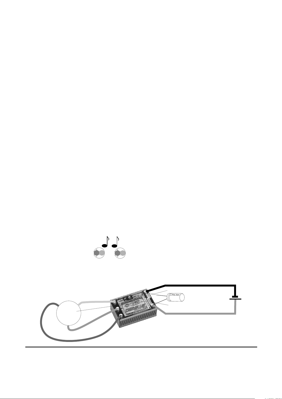
Connecting a brushless IFMAR motor to the controller (mode #1):
Use only motors produced by Graupner or GM-Racing which are designed for the desired voltage range! Poor quality
motors from other sources may lead to bad start-up characteristiques and, in the worst case, destroy the controller.
Connect the three cables of the controller with the motor by inserting the plug(s) or by soldering the cables in place. In
case the motor turns the wrong way round, swap two connectors on the motor. Never swap the connectors on the battery!
The motor and battery connector cables should all be the same length and never longer than 12cm. The longer the
cables, the heavier your model will be, and the more interference will be radioed by them.
On motors with Hall sensors you can now insert the plugs of the sensors into the controller (red = 3V, black = GND,
other colours = sensors 1-3). When using other products you should buy the corresponding adapters if desired. However,
the sensors needn't be connected if you want the motor to run without sensor support.
If you program “RESERVED” to the value 2 the motor will be commutated only with the hallsensors, if they are
connected. The sensor position will not be read automatically. The correct connection of the wires is very
important, otherwise the speed controller will be damaged. For IFMAR motors with bonded neodym magnets we
recommend this mode.
The motor can be connected to the same wire colours on the speed controller.
speed controller connect to EFRA/IFMAR motor (f.e. Reedy/LRP, GM #97214, GM #97215)
blue motor wire A = blue
yellow motor wire B = yellow
red motor wire C = orange
see figure!
When the Hall sensors are connected, the LEDs show the positions of two sensors but don't work in the way as described
later on in this documentation. Therefore we recommend disconnecting the sensors from the power supply before doing
the programming.
Connecting to the battery:
Connect the red battery cable to the drive battery (+).
Connect the black battery cable to the drive battery (-).
Programming plug and plug
for hall sensors
receiver wire
+
-
drive battery
M
Connecting a brushless IFMAR motor to the controller (Motorconfiguration #1)
power capacitor
blue
red
yellow
black
red
A
A
B
C
-
+
LED
Signal
rot
red gn
rot
red gn
depending on the MODE
1-4 short beeps
...
...
red LED flashes,
green LED on
3
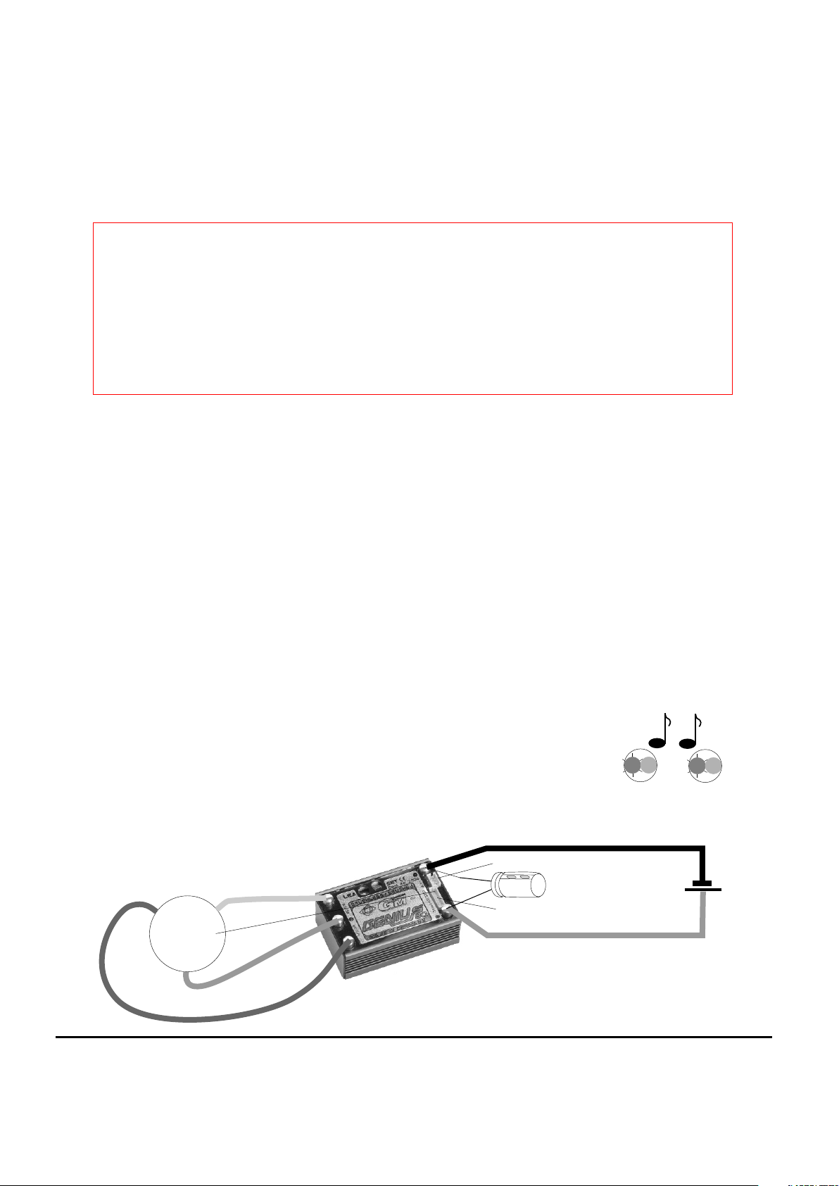
Anschluss eines bürstenlosen IFMAR Motors (Motorkonfiguration #1):
Benutzen Sie nur Motoren von Graupner oder GM-Racing, die für den verwendeten Spannungsbereich vorgesehen sind!
Motoren anderer Fabrikate könnten zu einem schlechten Anlauf führen und im schlimmsten Fall den Regler zerstören.
Verbinden/Verlöten Sie die drei Motoranschlüsse des Reglers mit den drei Anschlüssen des Motors. Sollte Ihr Motor falsch
herum laufen, so vertauschen Sie zwei Anschlüsse des Motors. Vertauschen Sie niemals die Anschlüsse am Akku!
Die Motor- und Akkuanschlusskabel sollten niemals länger als 12cm und möglichst gleich lang sein. Je länger die
Anschlusskabel sind, um so schwerer wird Ihr Modell und um so mehr Störungen strahlen die Kabel ab.
Bei GM Motoren mit Hallsensoren stecken Sie nun den Stecker der Hallsensoren in den Regler ein. (rot = 3V, schwarz =
GND, andere Farben = Sensoren 1-3). Bei Verwendung eines anderen Fabrikates kaufen Sie sich das entsprechende
Adapterkabel, falls gewünscht.
Ansonsten müssen die Hallsensoren nicht unbedingt angeschlossen sein. Der Motor läuft dann sensorlos.
Bei Programmierung der Funktion “RESERVED” auf den Wert 2 wird mit dieser Software der Motor bei
angeschlossenen Hallsensoren ausschließlich mit Hallsensoren angesteuert. Die Hallsensoren werden daher nicht
eingemessen. Der richtige Anschluss der Motorkabel ist daher zwingend, da sonst der Regler zerstört werden kann.
Für IFMAR Motoren mit Kunststoffgebundenen Neodymmagneten wir dieser Modus empfohlen.
Der Motor muss nach den Kabelfarben richtig angeschlossen werden.
Regler verbinden mit IFMAR/EFRA Motor (z. B. Reedy/LRP, GM #97214, #97215)
blaues Motorkabel A = blau
gelbes Motorkabel B = gelb
rotes Motorkabel C = orange
Bei angeschlossenen Hallsensoren zeigen die LEDs die Position zweier Hallsensoren an und funktionieren nicht wie später in
der Anleitung beschrieben. Es empfiehlt sich daher zur Programmierung des Reglers die Hallsensoren vor dem Anschließen
der Stromversorgungen abzustecken.
Anschluss des Akkus:
Verbinden Sie das rote Akkuanschlusskabel mit dem Fahrakku +.
Verbinden Sie das schwarze Akkuanschlusskabel mit dem Fahrakku -.
Nach dem Einschalten des Reglers meldet sich der Regler mit dem Modellmodus:
Wir empfehlen zwei Powerkondensatoren Best.-Nr. 91539.10 parallel an den Regler anzuschließen und einen
Powerkondensator am 3. Kanal des Empfängers an + und - richtig gepolt anzuschließen, um die max.
Leistung zu erhalten.
Auf rutschigen Fahrbahnen oder wenn der Motor “stottert” sollte Reserved = 6 programmiert werden, um für den Empfänger 4V
zur Verfügung zu stellen. Außerdem sollte am Empfänger am 3. Kanal ein Powerkondensator verwendet werden und Softgas
eventuell niedriger eingestellt werden.
Programmierstecker und
Stecker für Hallsensoren
Empfängerkabel
+
-
Antriebsakku
M
Anschluss eines bürstenlosen IFMAR Motors (Motorkonfiguration #1)
Powerkondensator
blau
rot
gelb
schwarz
rot
A
A
C
B
-
+
LED
TÖNE
rot
red gn
rot
red gn
Je nach Modus 1-4
kurze Pieptöne
...
...
rote LED blinkt,
grüne LED an

!"#
$#!
#% &
'&() *
' +
,&-.
-,#&
-%/0*#!- !&
+
!0
- &
!
'
1
2 03
0
1
%
2%4/
1
251
This manual suits for next models
2
Table of contents
Languages:
Other GM-Racing Engine manuals


